1.2.7 Packet Tracer – Connect a Network Based on a Network Diagram
Objectives
In this activity, you will complete a physical topology based on a provided network diagram.
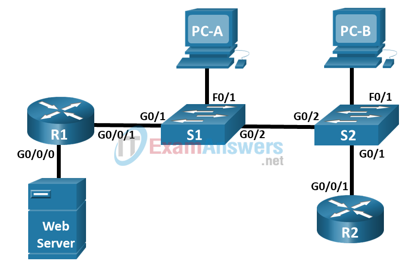
Network Diagram

Instructions
Network diagrams are essential to visualizing how devices are connected and work together. Diagrams can act as a road map when troubleshooting and maintaining the network.
There are two types of network diagrams: logical and physical. A logical network diagram shows how the devices communicate with each other and how the data is flowing through the network. A physical network diagram is similar to a floorplan. It shows all of the physical arrangements of the network, such as cable types, ports, server racks, and servers.
Part 1: Review the Logical Network Diagram.
Review the network diagram and record how the devices are connected in the Device Table below.
Device Table
| Device Name | Device Type | Local Interface | Connected Device and Port |
|---|---|---|---|
| R1 | Router / Cisco 4321 | G0/0/0 | Web Server Ethernet NIC |
| R1 | Router / Cisco 4321 | G0/0/1 | S1 G0/1 |
| S1 | Switch / Catalyst 2960 | G0/1 | R1 G0/0/1 |
| S1 | Switch / Catalyst 2960 | G0/2 | S2 G0/2 |
| S1 | Switch / Catalyst 2960 | F0/1 | PC-A Ethernet NIC |
| S2 | Switch / Catalyst 2960 | G0/1 | R2 G0/0/1 |
| S2 | Switch / Catalyst 2960 | G0/2 | S1 G0/2 |
| S2 | Switch / Catalyst 2960 | F0/1 | PC-B Ethernet NIC |
| R2 | Router / Cisco 4321 | G0/0/1 | S2 G0/1 |
| Web Server | Server | Ethernet | R1 G0/0/0 |
| PC-A | PC | Ethernet | S1 F0/1 |
| PC-B | PC | Ethernet | S2 F0/1 |
Part 2: Connect the Physical Devices.
Now you have determined how the devices are interconnected, you can use information from the network diagram to connect the devices in the rack in the wiring closet.
In Physical Mode in Packet Tracer, you can practice connecting the devices in the rack in the wiring closet.
Step 1: Determine the cable type.
From the network diagram, you have determined that the devices are connected via Ethernet cables from the network diagram.
On the cable peg board in the main wiring closet, there are a few different types of cables.
What color is the straight thru Ethernet cables in Packet Tracer?
The straight thru Ethernet cables are green.
Step 2: Connect the devices.
Using the Ethernet cables, connect the devices in the wiring closet according to the network diagram.
a. To connect router R1 to the Web Server, select an Ethernet cable from the peg board. The Web Server is the large device at the bottom of the equipment rack.
b. Click the Web Server FastEthernet0 port to connect the Ethernet cable.
c. Click the GigabitEthernet0/0/1 on R1 to complete the connection. You can zoom into the device by right-clicking the device > select Inspect Front. Click the magnifying glass to zoom into the front of the device. You can verify that the connection is up when the port LED lights are blinking green.
d. Repeat the procedure for all of the other connections to complete connecting the network. Note the PCs are located on the Table.
