0.0.0.0 Lab – Instructor Lab Using ASA 5505 (Instructor Version)
Topology
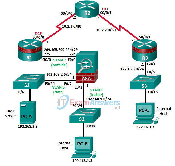
Note: ISR G1 devices use FastEthernet interfaces instead of GigabitEthernet interfaces.
IP Addressing Table
| Device | Interface | IP Address | Subnet Mask | Default Gateway | Switch Port |
|---|---|---|---|---|---|
| R1 | G0/0 | 209.165.200.225 | 255.255.255.248 | N/A | ASA E0/0 |
| S0/0/0 (DCE) | 10.1.1.1 | 255.255.255.252 | N/A | N/A | |
| R2 | S0/0/0 | 10.1.1.2 | 255.255.255.252 | N/A | N/A |
| S0/0/1 (DCE) | 10.2.2.2 | 255.255.255.252 | N/A | N/A | |
| R3 | G0/1 | 172.16.3.1 | 255.255.255.0 | N/A | S3 F0/5 |
| S0/0/1 | 10.2.2.1 | 255.255.255.252 | N/A | N/A | |
| ASA | VLAN 1 (E0/1) | 192.168.1.1 | 255.255.255.0 | NA | S2 F0/24 |
| VLAN 2 (E0/0) | 209.165.200.226 | 255.255.255.248 | NA | R1 G0/0 | |
| VLAN 3 (E0/2) | 192.168.2.1 | 255.255.255.0 | NA | S1 F0/24 | |
| PC-A | NIC | 192.168.2.3 | 255.255.255.0 | 192.168.2.1 | S1 F0/6 |
| PC-B | NIC | 192.168.1.3 | 255.255.255.0 | 192.168.1.1 | S2 F0/18 |
| PC-C | NIC | 172.16.3.3 | 255.255.255.0 | 172.16.3.1 | S3 F0/18 |
Objectives
Part 1: Initialize and Reload Network Devices
- Initialize the router and reload.
- Enable the security technology package license.
- Initialize the switch and reload.
- Initialize the ASA.
Part 2: Java Settings for PCs if Necessary
- Enable a secure HTTP server.
- Create a user account with privilege level 15.
- Configure SSH and Telnet access for local login.
Part 3: Access a Cisco Router Using a Mini-USB Console Cable
- Setup the physical connection with a mini-USB cable.
- Verify that the USB console is ready.
- Enable the COM port.
Part 4: Download and Install the AnyConnect Client Software Package
- Download the AnyConnect Secure Mobility Client software from cisco.com.
- Upload AnyConnect Secure Mobility Client to ASA 5505.
Background/Scenario
Part 1 of this instructor lab provides the steps for initializing devices back to their default settings. Part 2 of this lab provides the steps necessary to set Java settings on the PC hosts. Part 3 of this lab provides optional information on how to download, install, and use the Cisco USB driver on a Windows PC.
Required Resources
- 1 ASA 5505 (OS version 9.2(3), ASDM version 7.4(1), and Base license or comparable)
- 3 routers (Cisco 1941 with Cisco IOS Release 15.4(3)M2 image with a Security Technology package license)
- 3 switches (Cisco 2960 or comparable) (not required)
- 3 PCs (Windows 7 or Windows 8.1, with SSH client software installed)
- Serial and Ethernet cables, as shown in the topology
- Console cables to configure Cisco networking devices
Part 1: Initialize and Reload Network Devices
Task 1: Initialize the Router and Reload.
Step 1: Connect to the router.
Console into the router and enter privileged EXEC mode using the enable command.
Router> enable
Router#
Step 2: Erase the startup configuration file from NVRAM.
Type the erase startup-config command to remove the startup configuration from NVRAM.
Router# erase startup-config
Erasing the nvram filesystem will remove all configuration files! Continue? [confirm]
[OK]
Erase of nvram: complete
Router#
Step 3: Reload the router.
Issue the reload command to remove old configurations from memory. When prompted to proceed with reload, press Enter to confirm the reload. Pressing any other key will abort the reload.
Router# reload
Proceed with reload? [confirm]

*Nov 29 18:28:09.923: %SYS-5-RELOAD: Reload requested by console. Reload Reason: Reload Command.
You may receive a prompt to save the running configuration prior to reloading the router. Respond by typing no and press Enter.
System configuration has been modified. Save? [yes/no]: no
Step 4: Bypass the initial configuration dialog.
After the router reloads, you are prompted to enter the initial configuration dialog. Enter no and press Enter.
Would you like to enter the initial configuration dialog? [yes/no]: no
Step 5: Terminate the autoinstall program.
You will be prompted to terminate the autoinstall program. Respond yes and then press Enter.
Would you like to terminate autoinstall? [yes]: yes
Router>
Task 2: Initialize the Switch and Reload.
Step 1: Connect to the switch.
Console into the switch and enter privileged EXEC mode.
Switch> enable
Switch#
Step 2: Determine if there have been any VLANs created.
Use the show flash command to determine if any VLANs have been created on the switch.
Switch# show flash

Directory of flash:/
 2  -rwx        1919   Mar 1 1993 00:06:33 +00:00  private-config.text
    3  -rwx        1632   Mar 1 1993 00:06:33 +00:00  config.text
    4  -rwx       13336   Mar 1 1993 00:06:33 +00:00  multiple-fs
    5  -rwx    11607161   Mar 1 1993 02:37:06 +00:00  c2960-lanbasek9-mz.150-2.SE.bin
    6  -rwx         616   Mar 1 1993 00:07:13 +00:00  vlan.dat

32514048 bytes total (20886528 bytes free)
Switch#
Step 3: Delete the VLAN file.
a. If the vlan.dat file was found in flash, delete the file.
Switch# delete vlan.dat
Delete filename [vlan.dat]?
b. You will be prompted to verify the file name. At this point, you can change the file name or press Enter if you have entered the name correctly.
c. When you are prompted to delete this file, press Enter to confirm the deletion. Pressing any other key will abort the deletion.
Delete flash:/vlan.dat? [confirm]
Switch#
Step 4: Erase the startup configuration file.
Use the erase startup-config command to erase the startup configuration file from NVRAM. When prompted to remove the configuration file, press Enter to confirm the removal. Pressing any other key will abort the operation.
Switch# erase startup-config
Erasing the nvram filesystem will remove all configuration files! Continue? [confirm]
[OK]
Erase of nvram: complete
Switch#
Step 5: Reload the switch.
Reload the switch to remove old configuration information from memory. When prompted to reload the switch, press Enter to proceed with the reload. Pressing any other key will abort the reload.
Switch# reload
Proceed with reload? [confirm]
Note: You may receive a prompt to save the running configuration prior to reloading the switch. Type no and press Enter.
System configuration has been modified. Save? [yes/no]: no
Step 6: Bypass the initial configuration dialog.
After the switch reloads, you should see a prompt to enter the initial configuration dialog. Type no at the prompt and press Enter.
Would you like to enter the initial configuration dialog? [yes/no]: no
Switch>
Part 2: Java Settings on PCs
The next-generation Java Plug-in must be enabled and the security setting must be set to medium for the CCP configuration of IPS. To support CCP configuration of IPS and set the Java heap to 256 MB, the PC should be running Java JRE version 6 or newer. This is done using the runtime parameter –Xmx256m. The latest JRE for Windows can be downloaded from Oracle Corporation at http://www.oracle.com/.
Note: CCP is no longer used with CCNASv2 labs.
Step 1: Enable the next-generation Java Plug-in.
a. Open the Control Panel, and select Java to access the Java Control Panel.
b. In the Java Control Panel, click the Advanced
c. Locate the heading “Java Plug-in”. Select the checkbox to Enable the next-generation Plug-in. a browser restart is required.
d. Click Apply.
e. Click Yes to allow the changes. Click OK to acknowledge the changes.
Step 2: Change the Java security settings.
a. Click the Security
b. Change the Security Level to Medium by moving the slider.
c. Click Apply.
Step 3: Change the Java Applet Runtime settings.
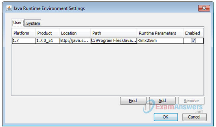
a. Click the Java tab and then the View button to change the Java Applet Runtime Settings.
b. Double-click the Runtime Parameters Type –Xmx256m in the box.
c. Click OK. Click OK again to exit the Java Control Panel.
Step 4: Restart all web browsers, including CCP if it opened, in order for the changes to take effect.
Part 3: Access a Cisco Router Using a Mini-USB Console Cable
If you are using a Cisco 1941 router or other Cisco IOS devices with a mini-USB console port, you can access the device console port using a mini-USB cable connected to the USB port on your computer.
Note: The mini-USB console cable is the same type of mini-USB cable used with other electronics devices, such as USB hard drives, USB printers, or USB hubs. These mini-USB cables can be purchased through Cisco Systems, Inc. or other third-party vendors. Please verify that you are using a mini-USB cable, not a micro-USB cable, to connect to the mini-USB console port on a Cisco IOS device.

Note: You must use either the USB port or the RJ-45 port. Do not use them simultaneously. When the USB port is used, it takes priority over the RJ-45 console port.
Step 1: Set up the physical connection with a mini-USB cable.
a. Connect the mini-USB cable to the mini-USB console port of the router.
b. Connect the other cable end to a USB port on the computer.
c. Turn on the Cisco router and computer.
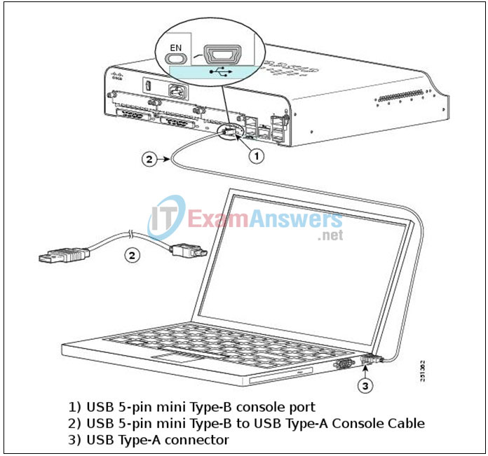
Step 2: Verify that the USB console is ready.
If you are using a Microsoft Windows-based PC and the USB console port LED indicator (labeled EN) does not turn green, please install the Cisco USB console driver.
A USB driver must be installed prior to being used on a Microsoft Windows-based PC that is connecting to a Cisco IOS device with a USB cable. The USB driver can be found on www.cisco.com with the related Cisco IOS device. The USB driver can be downloaded from the following location:
Note: You must have a valid Cisco Connection Online (CCO) account to download this file.
Note: The URL provided above is specifically related to the Cisco 1941 router. However, the USB console driver is not Cisco IOS device-model specific, but it only works with Cisco routers and switches. The computer requires a reboot after finishing the installation of the USB driver.
Note: After the files are extracted, the folder contains instructions for installation, removal, and the required drivers for different operating systems and architectures. Please choose the appropriate version for your system.
When the LED indicator for the USB console port has turned green, the USB console port is ready for access.
Step 3: Enable the COM port for the Windows 7 PC.
If you are using a Microsoft Windows 7 PC, you may need to perform the following steps to enable the COM port:
a. Click the Windows Start icon to access the Control Panel.
b. Open the Device Manager.
c. Click the Ports (COM & LPT) tree link to expand it. Right-click the USB Serial Port icon and choose Update Driver Software.

d. Choose Browse my computer for driver software.
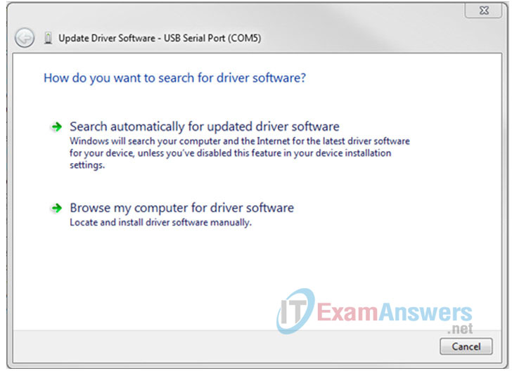
e. Choose Let me pick from a list of device drivers on my computer and click Next.
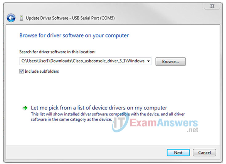
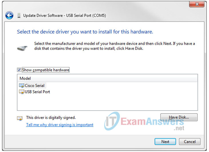
f. Choose the Cisco Serial driver and click Next.
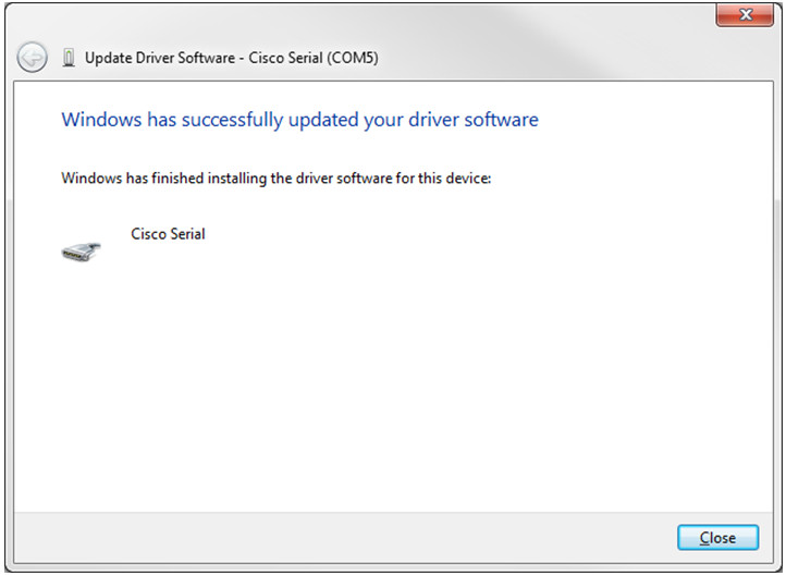
g. The device driver is installed successfully. Take note of the assigned port number listed at the top of the window. In this sample, COM 5 is used for communication with the router. Click Close.
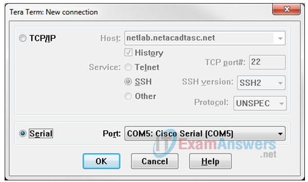
h. Open Tera Term. Click the Serial radio button and choose Port COM5: Cisco Serial (COM 5). This port should now be available for communication with the router. Click OK.
Part 4: Download and Install the AnyConnect Client Software Packages
Updated versions of Cisco’s AnyConnect Client software packages can be downloaded from Cisco.com. It is recommended that AnyConnect Secure Mobility Client release 4.1.00028 is downloaded and installed on the ASA 5505 for CCNAS. This release of the AnyConnect Secure Mobility Client has been tested on PCs running either the Windows 7 or Windows 8.1 OS.
Note: AnyConnect client version 4.5 is available for download in CCNA Security Instructor Resources.
Step 1: Download the AnyConnect Secure Mobility Client software packages from cisco.com.
a. Using a browser, connect to the www.cisco.com and log in.
b. Click Support > Security (VPN, Firewall) > AnyConnect VPN Client.
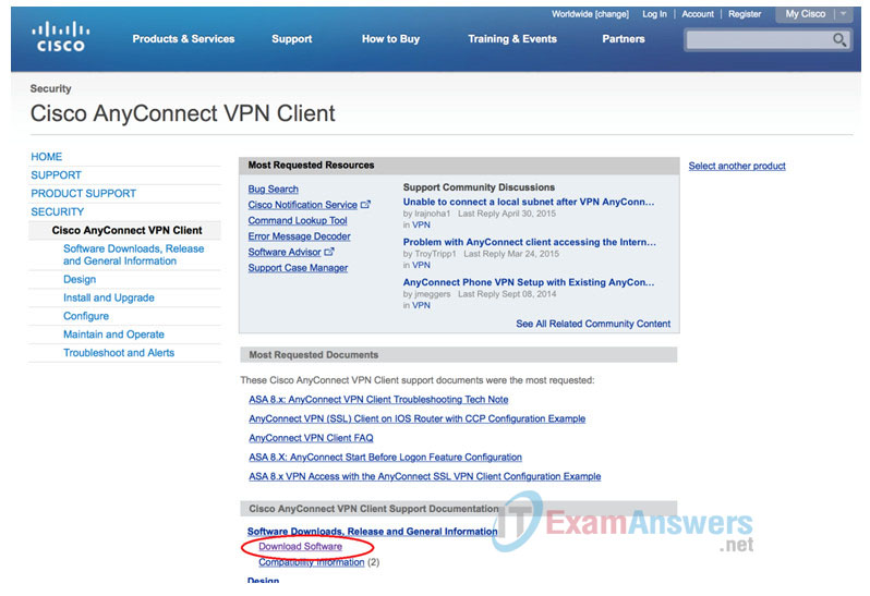
c. From the Cisco AnyConnect VPN Client screen, click Download Software.
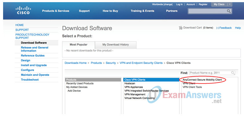
d. From the Download Software – Select a Product screen, click AnyConnect Secure Mobility Client.
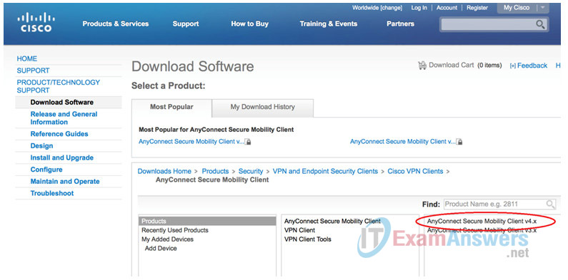
e. Click AnyConnect Security Mobility Client v4.x.
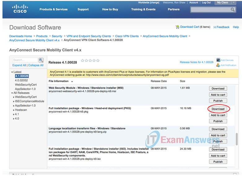
f. Use the scroll bar in the Download Software – AnyConnect Secure Mobility Client v4.x screen to locate the Full installation package – Windows / Head-end deployment (PKG) Click Download.
Note: The Windows package release 4.1.00028 filename is anyconnect-win-4.1.1.00028-k9.pkg.
Step 2: Upload the AnyConnect Secure Mobility Client to the ASA 5505.
a. After the anyconnect-win-4.1.00028-k9.pkg has been downloaded, connect the PC to the ASA 5505 E0/1 interface and assign it a static IP address of 168.1.3 with a subnet mask of 255.255.255.0.
Note: This PC will also need TFTP server software installed. Free or trial versions of TFTP server can be downloaded from the Internet. Use a web browser to search for “free windows tftp server” and refer to the software documentation for more information.
The IP addresses used in this example are for reference only. The file anyconnect-win-4.1.00028-k9.pkg is used in this example.
b. Configure the ASA’s VLAN with an IP address of 168.1.1, a subnet mask of 255.255.255.0, and the nameif to inside.
ciscoasa(config)# int vlan 1
ciscoasa(config-if)# ip address 192.168.1.1 255.255.255.0
ciscoasa(config-if)# nameif inside
INFO: Security level for "inside" set to 100 by default.
ciscoasa(config-if)# no shut
c. Activate interface E0/0.
ciscoasa(config-if)# int e0/1
ciscoasa(config-if)# no shut
ciscoasa(config-if)# end
d. Start the TFTP server software and verify that the anyconnect-win-4.1.00028-k9.pkg file is located in the default directory.
e. From the CLI on the ASA, issue the copy tftp://192.168.1.1/anyconnect-win-4.1.000028-k9.pkg flash:
ciscoasa# copy tftp://192.168.1.3/anyconnect-win-4.1.00028-k9.pkg flash:

Address or name of remote host [192.168.1.3]?

Source filename [anyconnect-win-4.1.00028-k9.pkg]?

Destination filename [anyconnect-win-4.1.00028-k9.pkg]?

Accessing tftp://192.168.1.3/anyconnect-win-4.1.00028-
k9.pkg...!!!!!!!!!!!!!!!!!!!!!!!!!!!!!!!!!!!!!!!!!!!!!!!!!!!!!!!!!!!!!!!!!!!!!!!!!!!!!!!!!!!!!!!!!!!!!!!!!!!!!!!!!!!!!!!!!!!!!!!!!!!!!!!!!!!!!!!!!!!!!!!!!!!!!!!!!!!!!!!!!!!!!!!!!!!!!!!!!!!!!!!!!!!!!!!!!!!!!!!!!!!!!!!!!!!!!!!!!!!!!!
Writing file disk0:/anyconnect-win-4.1.00028-k9.pkg...
!!!!!!!!!!!!!!!!!!!!!!!!!!!!!!!!!!!!!!!!!!!!!!!!!!!!!!!!!!!!!!!!!!!!!!!!!!!!!!!!!!!!!!!!!!!!!!!!!!!!!!!!!!!!!!!!!!!!!!!!!!!!!!!!!!!!!!!!!!!!!!!!!!!!!!!!!!!!!!!!!!!!!!!!!!!!!!!!!!!!!!!!!!!!!!!!!!!!!!!!!!!!!!!
16932458 bytes copied in 60.160 secs (282207 bytes/sec)
ciscoasa#
f. Issue the show flash command on the ASA to verify that the file has been uploaded to flash.
ciscoasa# show flash
--#--  --length--  -----date/time------  path
   54  30468096    Feb 13 2015 15:09:42  asa923-k8.bin
   19  2048        May 13 2015 18:42:24  crypto_archive
   20  2048        May 13 2015 18:42:54  coredumpinfo
   21  59          May 13 2015 18:42:54  coredumpinfo/coredump.cfg
   10  2048        Aug 29 2011 13:59:36  log
   57  26350916    Mar 26 2015 14:20:14  asdm-741.bin
   62  12998641    Aug 29 2011 14:04:10  csd_3.5.2008-k9.pkg
   63  2048        Aug 29 2011 14:04:12  sdesktop
   86  0           Aug 29 2011 14:04:12  sdesktop/data.xml
   64  4678691     Apr 16 2015 16:10:22  anyconnect-win-2.5.2014-k9.pkg
   65  6487517     Apr 16 2015 16:11:26  anyconnect-macosx-i386-2.5.2014-k9.pkg
   66  6689498     Apr 16 2015 16:12:18  anyconnect-linux-2.5.2014-k9.pkg
   68  16932458    May 21 2015 22:23:05  anyconnect-win-4.1.00028-k9.pkg

128573440 bytes total (23339008 bytes free)
ciscoasa#
Router Interface Summary Table
| Router Interface Summary | ||||
|---|---|---|---|---|
| Router Model | Ethernet Interface #1 | Ethernet Interface #2 | Serial Interface #1 | Serial Interface #2 |
| 1800 | Fast Ethernet 0/0 (F0/0) | Fast Ethernet 0/1 (F0/1) | Serial 0/0/0 (S0/0/0) | Serial 0/0/1 (S0/0/1) |
| 1900 | Gigabit Ethernet 0/0 (G0/0) | Gigabit Ethernet 0/1 (G0/1) | Serial 0/0/0 (S0/0/0) | Serial 0/0/1 (S0/0/1) |
| 2801 | Fast Ethernet 0/0 (F0/0) | Fast Ethernet 0/1 (F0/1) | Serial 0/1/0 (S0/1/0) | Serial 0/1/1 (S0/1/1) |
| 2811 | Fast Ethernet 0/0 (F0/0) | Fast Ethernet 0/1 (F0/1) | Serial 0/0/0 (S0/0/0) | Serial 0/0/1 (S0/0/1) |
| 2900 | Gigabit Ethernet 0/0 (G0/0) | Gigabit Ethernet 0/1 (G0/1) | Serial 0/0/0 (S0/0/0) | Serial 0/0/1 (S0/0/1) |
| Note: To find out how the router is configured, look at the interfaces, identify the type of router used, and how many interfaces the router has. There is no way to effectively list all the combinations of configurations for each router class. This table includes identifiers for the possible combinations of Ethernet and Serial interfaces in the device. The table does not include any other type of interface, even though a specific router may contain one. An example of this might be an ISDN BRI interface. The string in parenthesis is the legal abbreviation that can be used in Cisco IOS commands to represent the interface. | ||||
