14.3.3 Packet Tracer – Observe Traffic Flow in a Routed Network
Objectives
- Part 1: Observe Traffic Flow in an Unrouted LAN
- Part 2: Reconfigure the Network to Route Between LANs
- Part 3: Observe Traffic Flow in the Routed Network
Background / Scenario
The company that you work for has been asked to propose a new network design for XYZ LLC. XYZ is a startup company that has recently experienced success with their product offerings. They will be expanding, and their network will need to grow with them. Currently, the network is configured with a single IP network for hosts in all departments. This design has become inefficient and network delays are becoming increasingly noticeable. You have been asked to help prepare the proposal with the sales team. The sales team will propose a solution in which network efficiency is enhanced by implementing routing between separate department networks. You are working on a demonstration of how having multiple routed networks in a business can improve network efficiency. Follow the instructions to go through the demonstration to help propose a new network to XYZ LLC.
Instructions
Part 1: Observe Traffic Flow in an Unrouted LAN
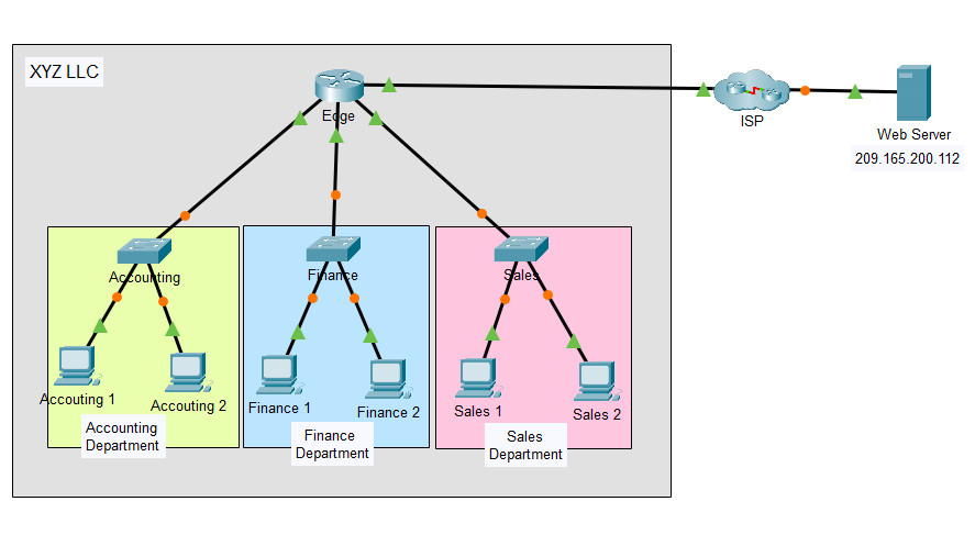
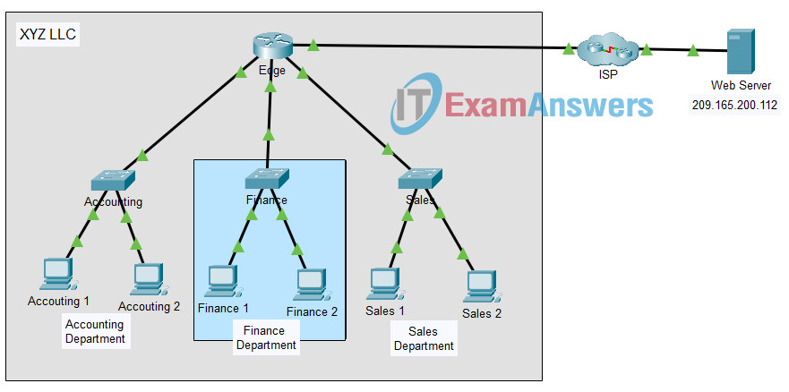
The XYZ network consists of about 150 devices that are connected to a LAN. The LAN is configured on a single IPv4 network. Hosts in different departments are connect to switches which are then connected to the Edge router. The router only routes traffic between the LAN and the internet, represented by the ISP cloud. Because only one IP network is used in the LAN, all departments are on the same network.
The Packet Tracer topology is simplified. It only shows some of the departments and hosts. Assume that the behavior that you will demonstrate is happening at far greater scale than what is shown in the PT network.
In this part, you will use Packet Tracer simulation mode to observe how traffic flows through an unrouted LANs.
Step 1: Clear the ARP cache on host Sales 1.
Hover your mouse over the Sales 1 host to see its IP address. Make note of it.
In this case, the IP address of Sales 1 is: 192.168.1.4
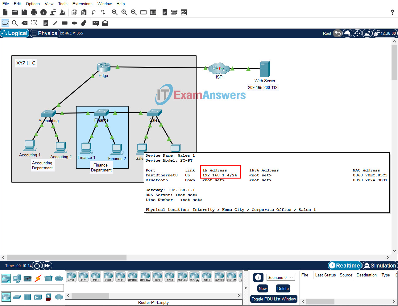
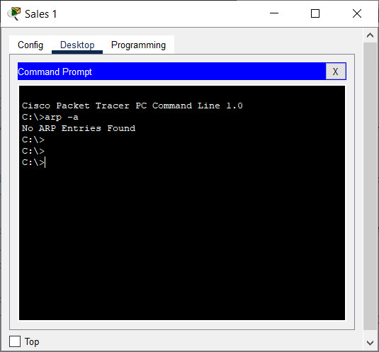
a. Click Sales 1 > Desktop tab > Command Prompt, and then enter the arp -a command. There should be no MAC addresses in the ARP cache. If there are entries in the ARP cache, use the arp -d command to delete them.
Step 2: Observe traffic flow in the network.
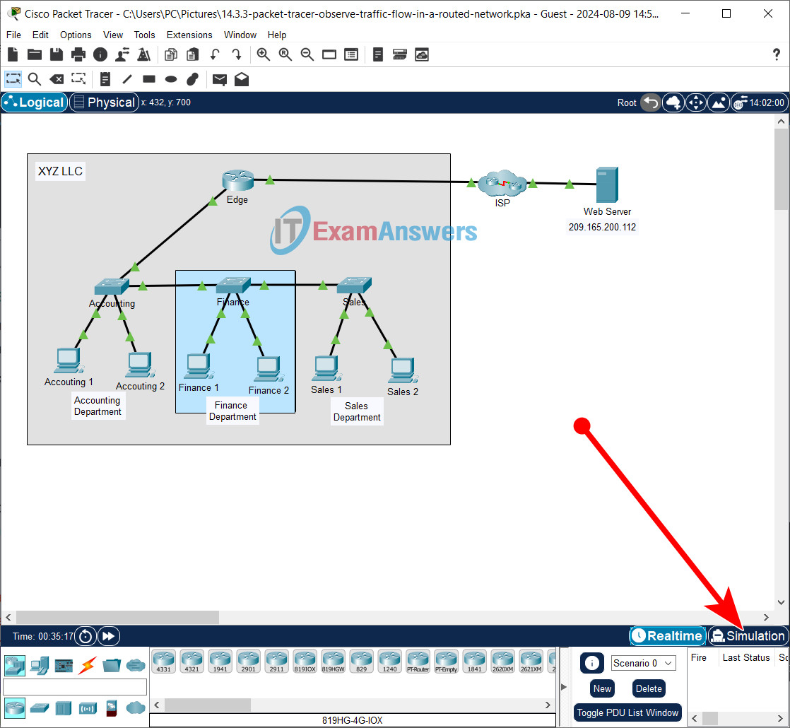
a. Click the Simulation mode button in the lower right-hand corner of the PT window to switch from Realtime to Simulation mode.
b. Open the Command Prompt for Sales 2, and then enter the ping command followed by the IP address of Sales 1.
c. Use the Capture then Forward button (the triangle pointing to the right with a vertical bar attached) in the Play Controls of the Simulation Panel to begin to execute the ping command. You will see a colored envelope icon appear next to Sales 2. This represents a PDU. Click the Capture then Forward button to move the PDU to the first device on its path to the destination device. Click the PDU envelope to inspect the contents.
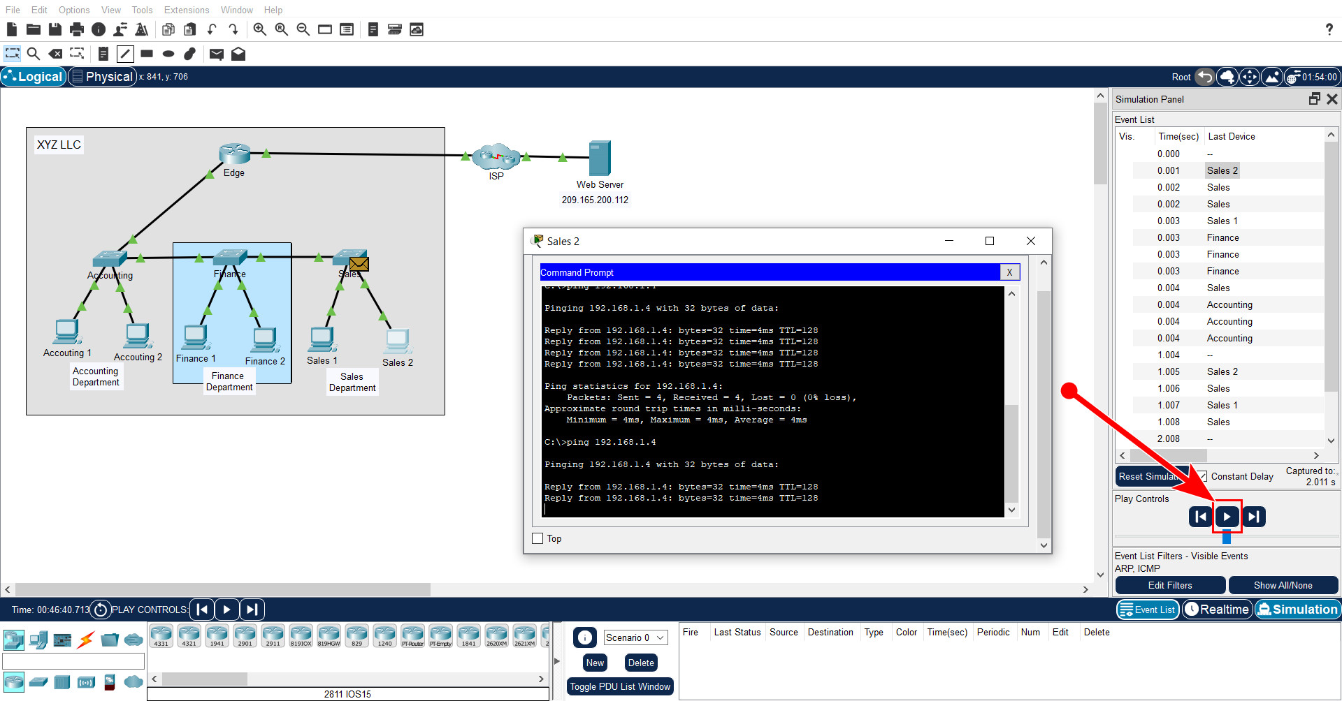
Capture then Forward button
What are the source and destination MAC and IP addresses for the frame and packet?
The frame source MAC address is the MAC address of Sales 1. The destination MAC address is the MAC broadcast address of FFFF.FFFF.FFFF. The packet source IP address is the IP address of Sales 1. The destination IP address is the destination of Sales 2.
Why is the destination MAC address the broadcast address?
Because the host ARP cache is empty, the host must first issue an ARP request to obtain the destination MAC address so that the frame can be addressed to the Sales 1.
d. Advance the PDUs through the network until a new PDU (different color) is created at Sales 2.
Which hosts and other types of devices needed to process the ARP request packets?
All hosts and the router interface
What is the impact of this on efficient operation of the network as it is currently configured?
Even though the destination for the ping requests may be adjacent to the requesting source, if the host has an empty ARP cache, an ARP request is sent that must be processed by every host on the network. ARP cache entries are removed after a preset period of time. With many hosts on a network, ARP broadcasts will be issued more frequently. This requires network resources to be taken away for the work-related traffic.
e. A new PDU with a different color has appeared at Sales 2. Click the new PDU and inspect its contents. Look at the outbound PDU details.
What type of PDU is this?
It is the first ICMP echo-request packet that is issued by ping from host Sales 2.
f. Return to Realtime mode.
Part 2: Reconfigure the Network to Route Between LANs.
In this part, you will demonstrate the benefits of routing between department networks. First, you will cable each network switch to connect directly to a router interface. Then, you will reconfigure the hosts to receive addresses on two new IPv4 networks that are created by the router.
Step 1: Change device connections.
The three switches are connected to each other with copper straight through cables.
a. For the cable that connects the Accounting switch with Finance switch, click the green triangle on the Accounting switch side of the link.
b. Drag that end of the cable to the Edge router and connect the cable to port GigabitEthernet 1/0.
c. Repeat this step for the link between Finance and Sales. Connect to the available GigabitEthernet port.
Step 2: Configure the hosts with addresses on the new LANs.
Each interface of the Edge router was previously configured to put each department on its own IPv4 network. The hosts will receive their new IP addresses from the router. However, it will take time for the hosts on the Finance and Sales networks to receive their new IP addresses. (The hosts on the Accounting network will remain on 192.168.1.0/24.)
a. To speed up the process of getting new IP addresses, open a Command Prompt on each of the four devices in the Finance and Sales networks.
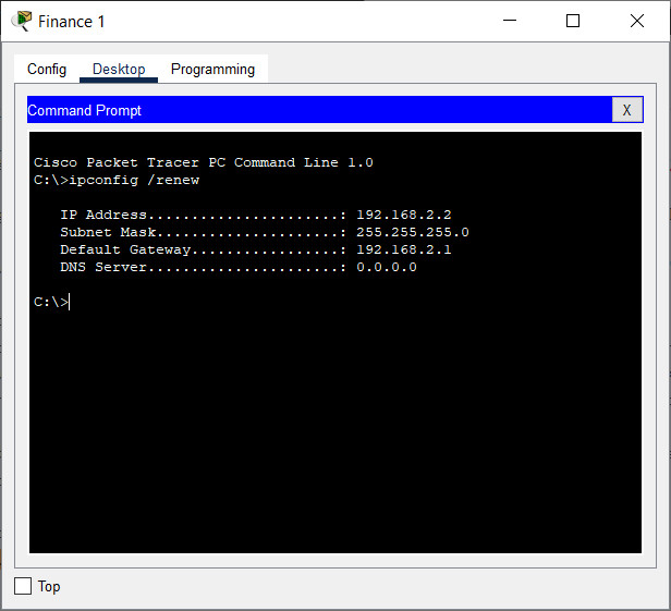
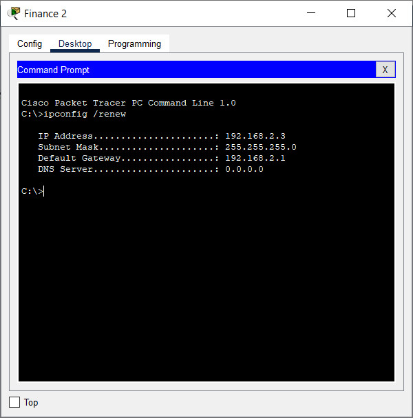
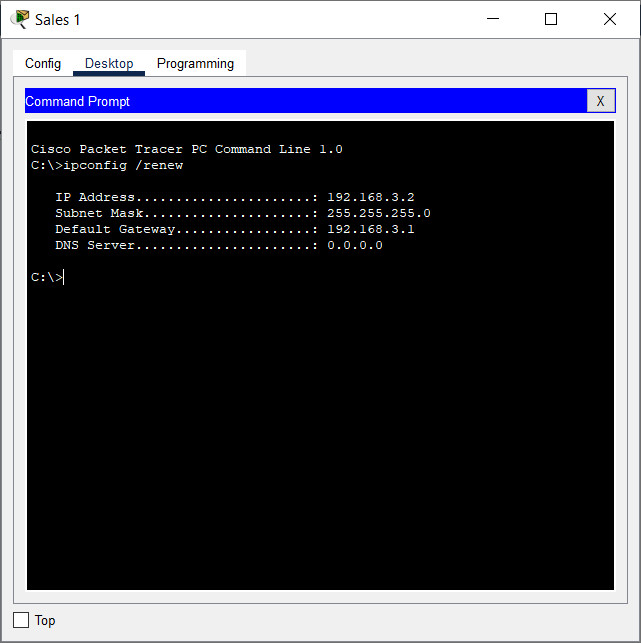
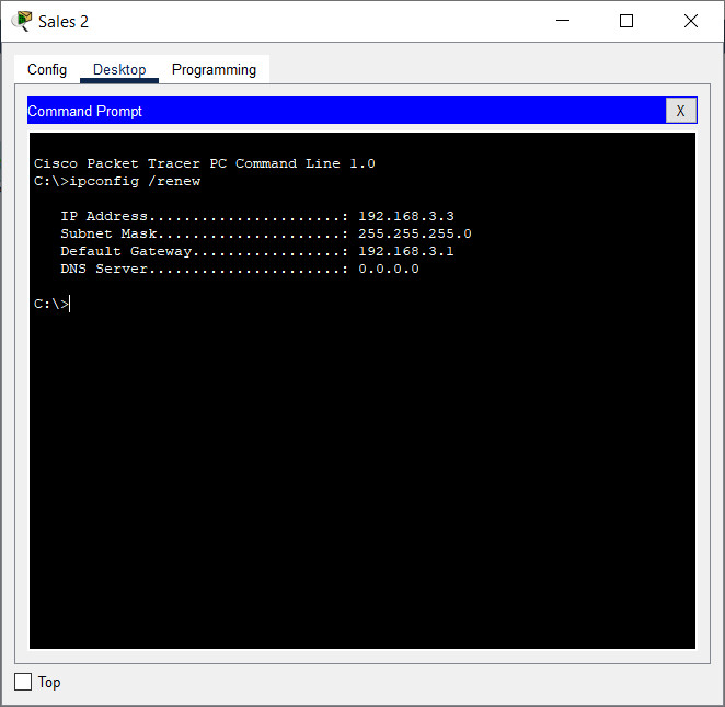
b. Enter the ipconfig /renew command. This will force the host to request a new IP address from the DHCP server that is running on the Edge router. You should see confirmation of new IP addressing.
What IPv4 network is assigned to the Finance network?
192.168.2.0/24
What IPv4 network is assigned to the Sales network?
192.168.3.0/24
Part 3: Observe Traffic Flow in the Routed Network.
In this part, you will observe how traffic now flows through a routed network.
Step 1: Ping Sales 1 from Sales 2.
a. Return to the Command Prompt for Sales 2 and verify that its ARP cache is empty. If it is not, delete any entries.
b. Switch to Simulation mode.
c. Ping Sales 1 from Sales 2.
d. Use the Capture then Forward button to step the PDUs through the network. Observe how the ARP request message flows through the network this time.
Which devices receive the ARP broadcasts this time?
Only Sales 1 and the router interface that is connected to the Sales department network process the PDU.
Step 2: Ping other hosts.
Repeat this demo by pinging other hosts and the internet server. Observe the flow of the ARP request PDUs.
What is the benefit of using multiple IPv4 networks, or subnetworks, within an enterprise?
A major benefit of using multiple IP networks is the containment of traffic within relevant parts of the network without unnecessarily impacting performance on irrelevant parts of the network.
Note: The network topology that is used in the activity is for demonstration purposes only. While it is possible that a real enterprise network could use a router in this way, there are more optimal topologies that achieve these results. You will learn about other design approaches in later networking courses.

