Packet Tracer – Configuring Multiarea OSPFv2 (Instructor Version)
Instructor Note: Red font color or Gray highlights indicate text that appears in the instructor copy only.
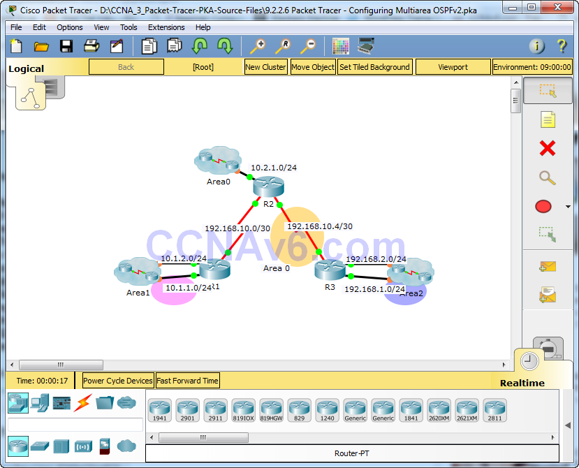
Topology

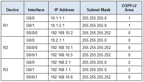
Addressing Table

Objectives
Part 1: Configure Multiarea OSPFv2
Part 2: Verify and Examine Multiarea OSPFv2
Background
In this activity, you will configure multiarea OSPFv2. The network is already connected and interfaces are configured with IPv4 addressing. Your job is to enable multiarea OSPFv2, verify connectivity, and examine the operation of multiarea OSPFv2.
Part 1: Configure OSPFv2
Step 1: Configure OSPFv2 on R1.
Configure OSPFv2 on R1 with a process ID of 1 and a router ID of 1.1.1.1.
R1(config)# router ospf 1
R1(config-router)# router-id 1.1.1.1
Step 2: Advertise each directly connected network in OSPFv2 on R1.
Configure each network in OSPFv2 assigning areas according to the Addressing Table.
R1(config-router)# network 10.1.1.0 0.0.0.255 area 1
R1(config-router)# network 10.1.2.0 0.0.0.255 area 1
R1(config-router)# network 192.168.10.0 0.0.0.3 area 0
Step 3: Configure OSPFv2 on R2 and R3.
Repeat the steps above for R2 and R3 using a router ID of 2.2.2.2 and 3.3.3.3, respectively.
R2(config)# router ospf 1
R2(config-router)# router-id 2.2.2.2
R2(config-router)# network 10.2.1.0 0.0.0.255 area 0
R2(config-router)# network 192.168.10.0 0.0.0.3 area 0
R2(config-router)# network 192.168.10.4 0.0.0.3 area 0
!
R3(config)# router ospf 1
R3(config-router)# router-id 3.3.3.3
R3(config-router)# network 192.168.2.0 0.0.0.255 area 2
R3(config-router)# network 192.168.1.0 0.0.0.255 area 2
R3(config-router)# network 192.168.10.4 0.0.0.3 area 0
Part 2: Verify and Examine Multiarea OSPFv2
Step 1: Verify connectivity to each of the OSPFv2 areas.
From R1, ping each of the following remote devices in area 0 and area 2: 192.168.1.2, 192.168.2.2, and 10.2.1.2.
Step 2: Use show commands to examine the current OSPFv2 operations.
Use the following commands to gather information about your OSPFv2 multiarea implementation.
show ip protocols
show ip route
show ip ospf database
show ip ospf interface
show ip ospf neighbor
Reflection Questions
1. Which router(s) are internal routers? R2
2. Which router(s) are backbone routers? R1, R2, and R3 are all backbone routers.
3. Which router(s) are area border routers? R1 and R3
4. Which router(s) are autonomous system routers? None, all active interfaces on all three routers connect to an OSPF area.
5. Which routers are generating Type 1 LSAs? All OSPF routers generate Type 1 LSAs.
6. Which routers are generating Type 2 LSAs? Hidden routers in each of the areas that are DRs are. Router IDs 4.4.4.4, 5.5.5.5, 6.6.6.6, 9.9.9.9
7. Which routers are generating Type 3 LSAs? R1 and R3 because each is an ABR and needs to flood area information from one area to the other.
8. Which routers are generating Type 4 and 5 LSAs? None, because there is not an ASBR in the network.
9. How many inter area routes does each router have? R1 and R3 have two IAs and R2 has 4 IAs.
10. Why would there usually be an ASBR in this type of network? ASBR is used to connect external routing domains.
Suggested Scoring Rubric
Packet Tracer scores 80 points. Each of the Reflection Questions is worth 2 points.
