Command
VTP Pruning
Use
This is the legacy way of configuring VTP pruning. VTP pruning spares bandwidth and adds to security by paying attention to what switches have interfaces assigned to VLANs. If a switch isn’t using a particular VLAN, the VTP server will block traffic from the VLAN going to that switch.
Syntax
Switch(vlan)#vtp pruning
Example

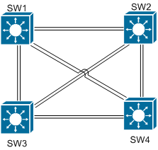
In the below example we will turn on VTP pruing for SW1. On SW2, we can see that Fa0/9 and Fa0/12 are in VLAN 11.
SW2(config)#do show vlan brief

VLAN Name Status Ports
—- ——————————– ——— ——————————-
1 default active Fa0/1, Fa0/2, Fa0/3, Fa0/4
Fa0/5, Fa0/6, Fa0/7, Fa0/8
Fa0/10, Fa0/11, Fa0/13, Fa0/14
Fa0/15, Fa0/16, Fa0/17, Fa0/18
Fa0/19, Fa0/20, Fa0/21, Fa0/22
Gi0/1, Gi0/2
10 VLAN0010 active
11 VLAN0011 active Fa0/9, Fa0/12
12 VLAN0012 active
13 VLAN0013 active
14 VLAN0014 active
15 VLAN0015 active
16 VLAN0016 active
17 VLAN0017 active
18 VLAN0018 active
19 VLAN0019 active
20 VLAN0020 active
99 VLAN0099 active
555 VLAN0555 active
After that, we turn on switching for SW1. Looking at the show interface trunk output, we can see that Fa0/23 is allowing VLAN11 traffic.
SW1(vlan)#vtp pruning
Pruning switched on
SW1(vlan)#exit
APPLY completed.
Exiting….
SW1#

SW1#conf t
SW1(config)#do show interface trunk

Port Mode Encapsulation Status Native vlan
Fa0/19 desirable n-isl trunking 1
Fa0/20 desirable n-isl trunking 1
Fa0/21 desirable n-isl trunking 1
Fa0/22 desirable n-isl trunking 1
Fa0/23 desirable n-isl trunking 1
Fa0/24 desirable n-isl trunking 1

Port Vlans allowed on trunk
Fa0/19 1-4094
Fa0/20 1-4094
Fa0/21 1-4094
Fa0/22 1-4094
Fa0/23 1-4094
Fa0/24 1-4094

Port Vlans allowed and active in management domain
Fa0/19 1,10-20,99,555
Fa0/20 1,10-20,99,555
Fa0/21 1,10-20,99,555
Fa0/22 1,10-20,99,555
Fa0/23 1,10-20,99,555

Port Vlans allowed and active in management domain
Fa0/24 1,10-20,99,555

Port Vlans in spanning tree forwarding state and not pruned
Fa0/19 1
Fa0/20 1
Fa0/21 1
Fa0/22 1
Fa0/23 1,11
Fa0/24 1
Checking show cdp neighbor on SW1, we see that Fa0/23 is connected to SW2.
SW1(config)#do show cdp neighbor
Capability Codes: R – Router, T – Trans Bridge, B – Source Route Bridge
S – Switch, H – Host, I – IGMP, r – Repeater, P – Phone

Device ID Local Intrfce Holdtme Capability Platform Port ID
SW4 Fas 0/20 123 S I WS-C3560-2Fas 0/20
SW4 Fas 0/19 123 S I WS-C3560-2Fas 0/19
SW2 Fas 0/24 171 S I WS-C3560-2Fas 0/24
SW2 Fas 0/23 171 S I WS-C3560-2Fas 0/23
SW3 Fas 0/22 169 S I WS-C3560-2Fas 0/22
SW3 Fas 0/21 169 S I WS-C3560-2Fas 0/21
R2 Fas 0/2 145 R S I 3825 Fas 1/0
R1 Fas 0/1 137 R S I 2811 Fas 0/0
R4 Fas 0/4 128 R S I 2811 Fas 0/0
R5 Fas 0/5 137 R S I 2811 Fas 0/0
