Interconnection Technologies


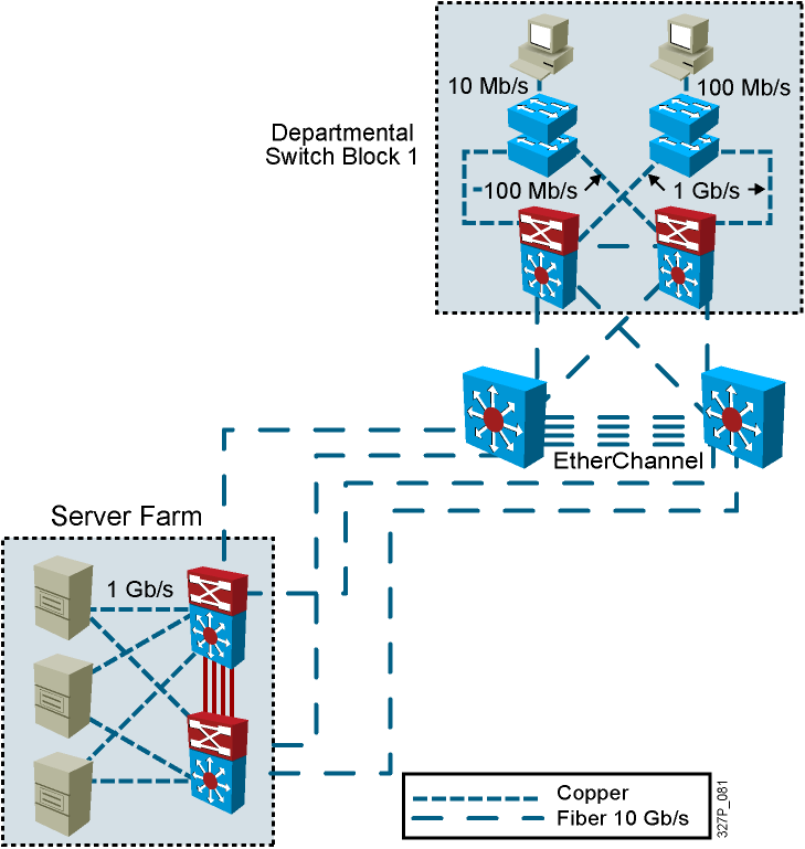
Determining Equipment and Cabling Needs
Each link provides adequate bandwidth for the total aggregate traffic over that link.
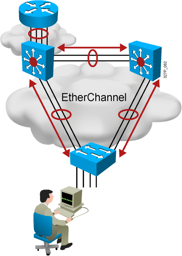
Advantages of EtherChannel
- Logical aggregation of similar links between switches
- Load-shares across links
- Viewed as one logical port to STP
- Redundancy
Redundant Topology

- Redundant topology eliminates single points of failure.
- Redundant topology causes broadcast storms, multiple frame copies, and MAC address table instability problems.
Broadcast Frames
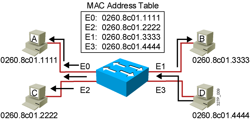
- Station D sends a broadcast frame.
- Broadcast frames are flooded to all ports except the originating port.
Broadcast Storms
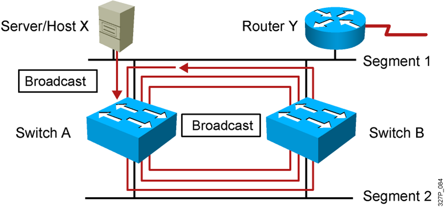
- Host X sends a broadcast.
- Switches continue to propagate broadcast traffic over and over.
Multiple Frame Copies
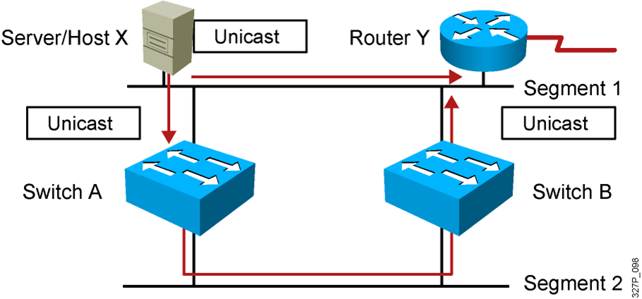
- Host X sends a unicast frame to router Y.
- The MAC address of router Y has not been learned by either switch.
- Router Y will receive two copies of the same frame.
MAC Database Instability

- Host X sends a unicast frame to router Y.
- The MAC address of router Y has not been learned by either switch.
- Switches A and B learn the MAC address of host X on port 1.
- The frame to router Y is flooded.
- Switches A and B incorrectly learn the MAC address of host X on port 2.
Loop Resolution with STP

- Provides a loop-free redundant network topology by placing certain ports in the blocking state
- Published in the IEEE 802.1D specification
- Enhanced with the Cisco PVST+ implementation
Spanning-Tree Operation
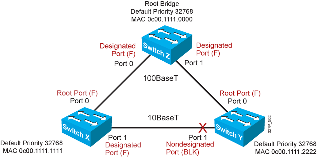
- One root bridge per broadcast domain.
- One root port per nonroot bridge.
- One designated port per segment.
- Nondesignated ports are unused.
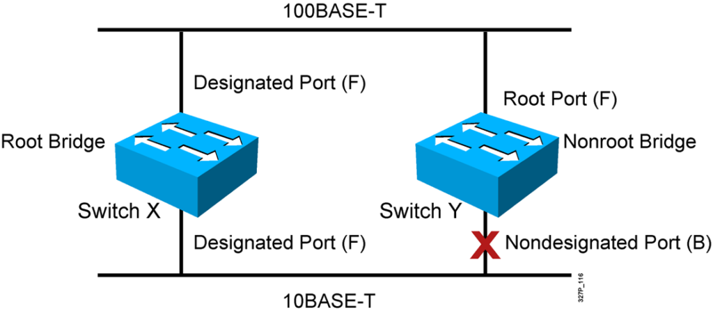
STP Root Bridge Selection


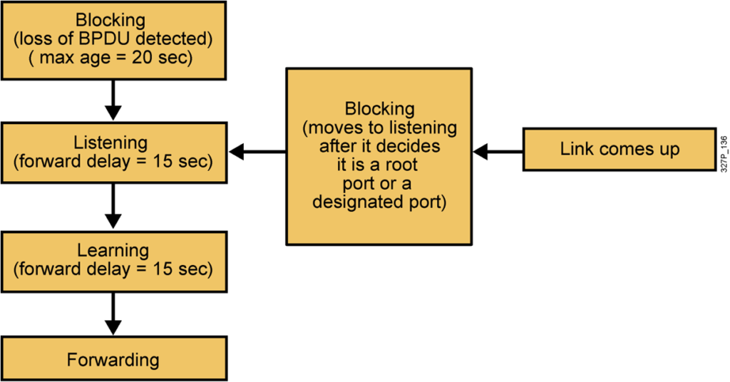
Spanning-Tree Port States
Spanning tree transits each port through several different states:
Describing PortFast
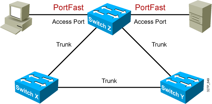
PortFast is configured on access ports, not trunk ports.
Configuring and Verifying PortFast

Spanning-Tree Operation Example
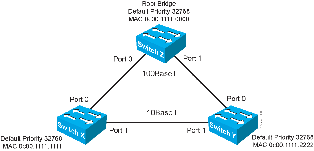
Spanning-Tree Path Cost

Spanning-Tree Recalculation
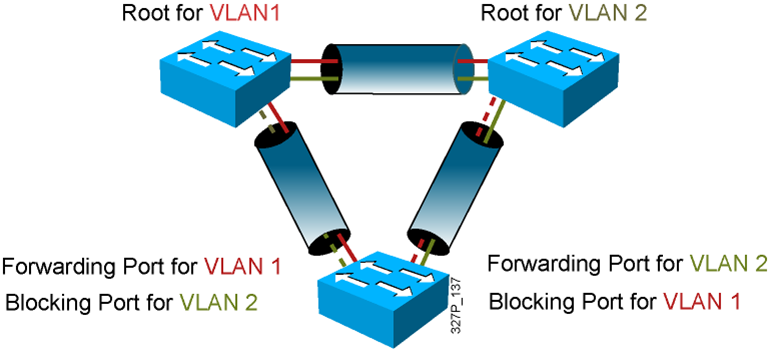
Per VLAN Spanning Tree Plus
PVST+ Extended Bridge ID

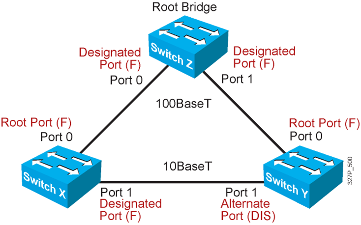
Rapid Spanning Tree Protocol
Default Spanning-Tree Configuration
- Cisco Catalyst switches support three types of STPs:
–PVST+
–PVRST+
–MSTP
- The default STP for Cisco Catalyst switches is PVST+ :
–A separate STP instance for each VLAN
–One root bridge for all VLANs
–No load sharing
PVRST+ Configuration Guidelines
1.Enable PVRST+.
2.Designate and configure a switch to be the root bridge.
3.Designate and configure a switch to be the secondary root bridge.
4.Verify the configuration.
PVRST+ Implementation Commands

Verifying PVRST+

Configuring the Root and Secondary Bridges

Configuring the Root and Secondary Bridges: SwitchA

Configuring the Root and Secondary Bridges: SwitchB

Summary
- A redundant switched topology includes multihomed switches and EtherChannel.
- A redundant switched topology causes looping issues such as broadcast storms.
- The 802.1D STP establishes a loop-free network.
- The original STP has been enhanced by PVST+ and RSTP.
