Issues in a Poorly Designed Network

- Unbounded failure domains
- Large broadcast domains
- Large amount of unknown MAC unicast traffic
- Unbounded multicast traffic
- Management and support challenges
- Possible security vulnerabilities
VLAN Overview
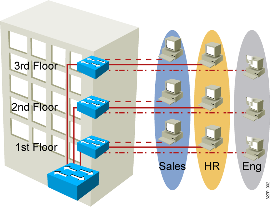
- Segmentation
- Flexibility
- Security
Designing VLANs for an Organization
- VLAN design must take into consideration the implementation
of a hierarchical network addressing scheme. - The benefits of hierarchical addressing are:
– Ease of management and troubleshooting
– Minimization of errors
– Reduced number of routing table entries
Guidelines for Applying IP Address Space
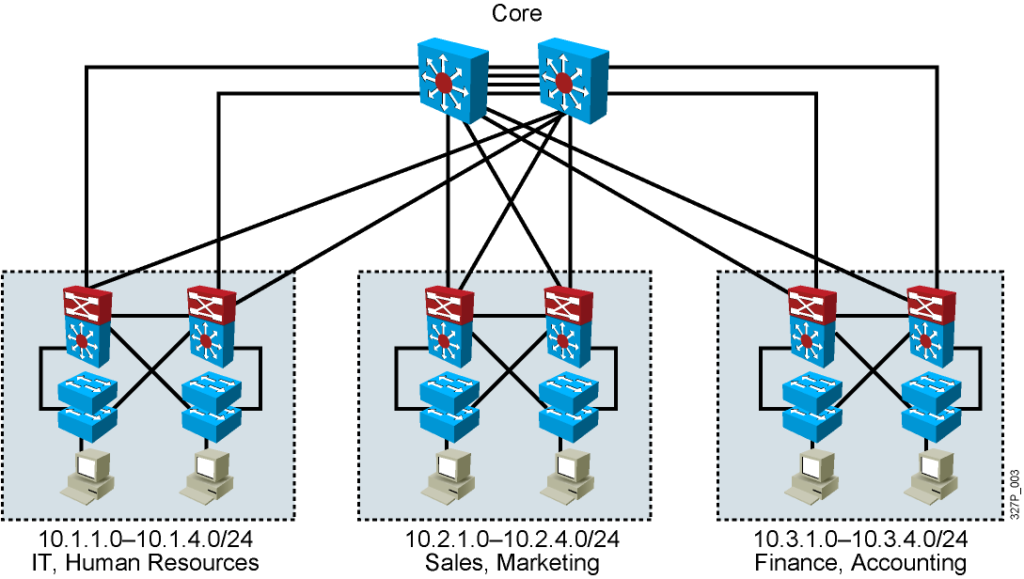
- Allocate one IP subnet per VLAN.
- Allocate IP address spaces in contiguous blocks.
Network Traffic Types
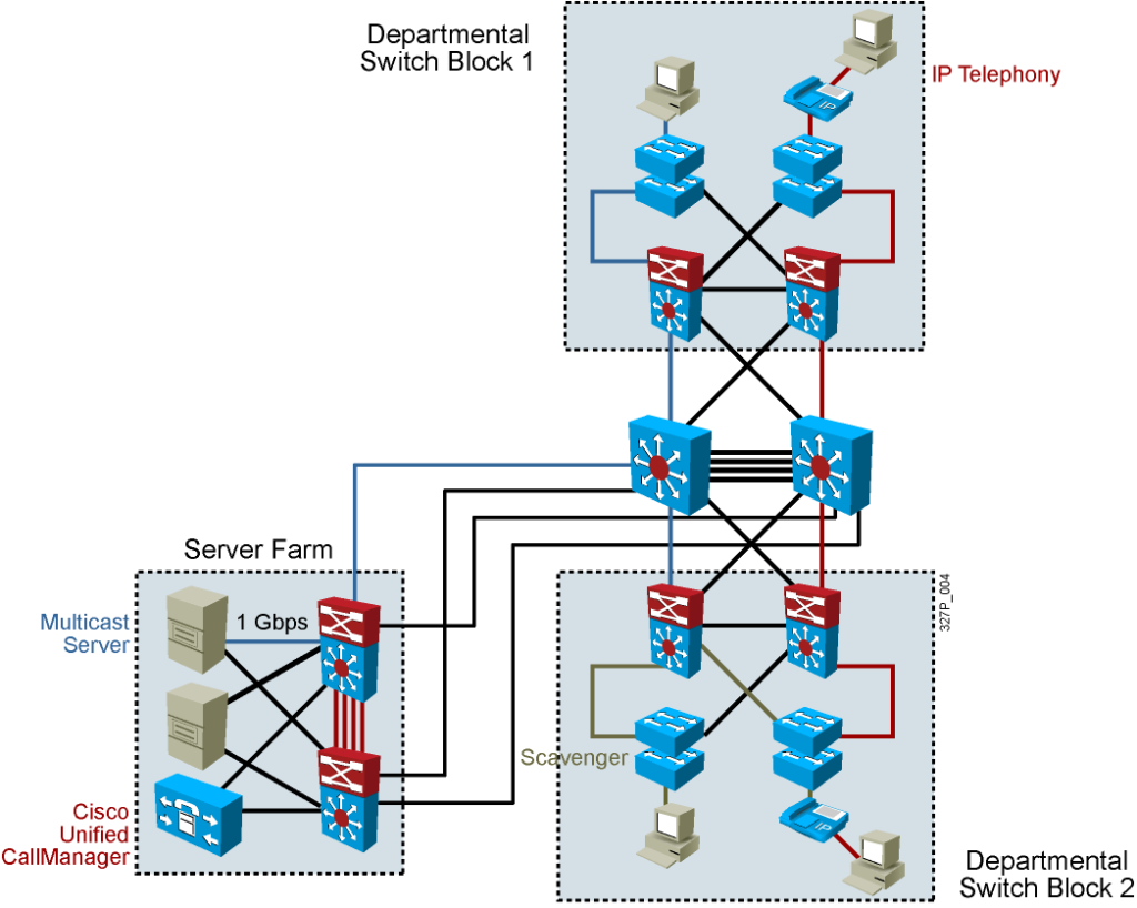
Traffic types to consider when designating VLANs:
- Network management
- IP telephony
- IP Multicast
- Normal data
- Scavenger class
Advantages of Voice VLANs
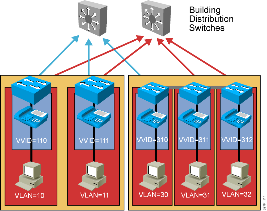
- Phones segmented in separate logical networks
- Privides network segmentation and control
- Allows administrators to create and enforce QoS
- Lets administrators add and enforce security policies
VLAN Operation
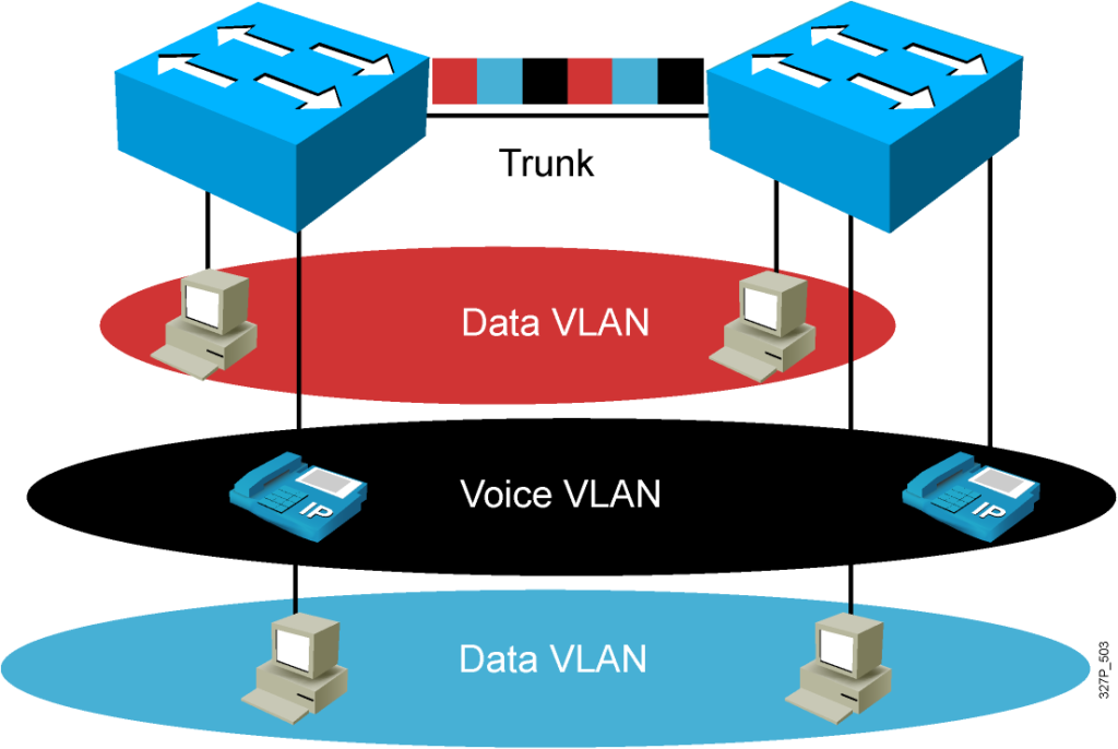
VLAN Membership Modes
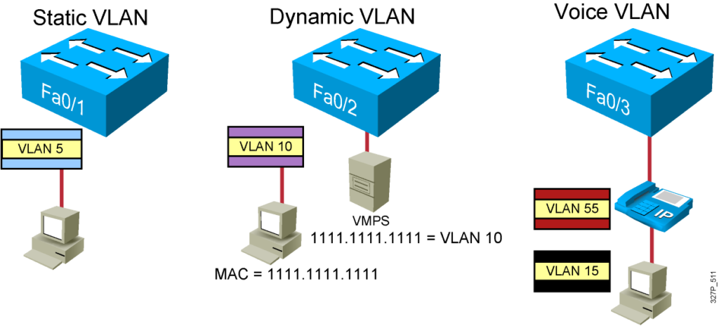
Static VLAN

Static Port mode configuration
Switch#config t
Switch(config)#interface fastEthernet0/15
Switch(config-if)#switchport mode access
Switch(config-if)#switchport access vlan 10
Switch(config-if)#end
If you assign an interface to not exist VLAN
- Exception.
- The new VLAN is created.
Dynamic VLAN

– Configured using VLAN Membership Policy Server (VMPS)
– Assign switch ports to VLANs dynamically: based on the source MAC address of the device connected to the port
Voice VLAN

A port is configured to be in voice mode:
-Support an IP phone attached to
-Before you configure a voice VLAN on the port, you need to first configure a VLAN for voice and a VLAN for data.
Voice mode Configuration
Switch#config t
Switch(config)#interface fastEthernet 0/15
Switch(config-if)#mls qos trust cos
Switch(config-if)#switchport voice vlan 99
Switch(config-if)#switchport mode access
Switch(config-if)#switchport access vlan 10
Switch(config-if)#end
802.1Q Trunking
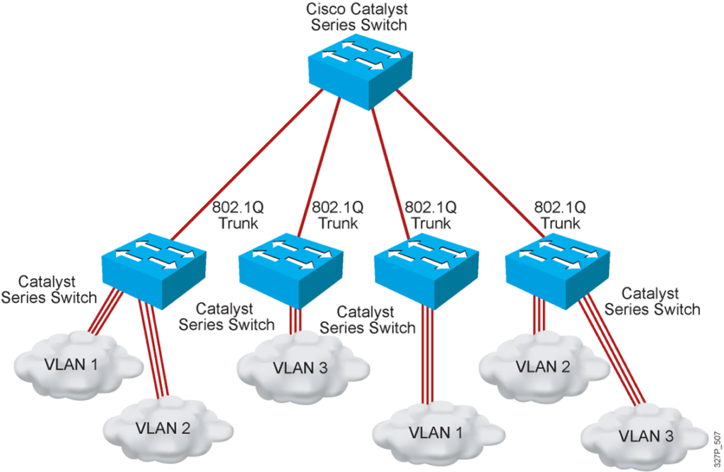
Both trunking protocols support the same number of VLANs, specifically 4094 VLANs.
Both protocols use 12 bits of the VLAN header to number VLANs, supporting 212, or 4096,
VLAN IDs, minus two reserved values (0 and 4095). Of the supported VLANs, note that
VLAN IDs 1–1005 are considered to be normal range VLANs, whereas values higher than 1005 are called extended range VLANs. This distinction matters in regard to the VLAN
Trunking Protocol (VTP), which is covered in the next section.
ISL and 802.1Q both support a separate instance of Spanning Tree Protocol (STP) for each
VLAN, but with different implementation details, as explained in Chapter 2. For campus
LANs with redundant links, using only one instance of STP means that some links sit idle under normal operations, with those links only being used when another link fails. By supporting multiple instances of STP, engineers can tune the STP parameters so that under normal operations, some VLANs’ traffic uses one set of links and other VLANs’ traffic uses other links, taking advantage of all the links in the network.
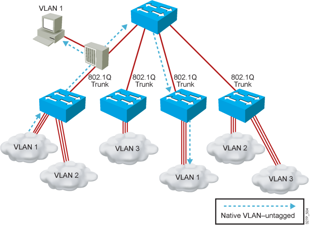
One final key difference between ISL and 802.1Q covered here relates to a feature called the native VLAN. 802.1Q defines one VLAN on each trunk as the native VLAN, whereas
ISL does not use the concept. By default, the 802.1Q native VLAN is VLAN 1. By definition, 802.1Q simply does not add an 802.1Q header to frames in the native VLAN.
When the switch on the other side of the trunk receives a frame that does not have an 802.1Q header, the receiving switch knows that the frame is part of the native VLAN. Note that because of this behavior, both switches must agree which VLAN is the native VLAN.
802.1Q Frame
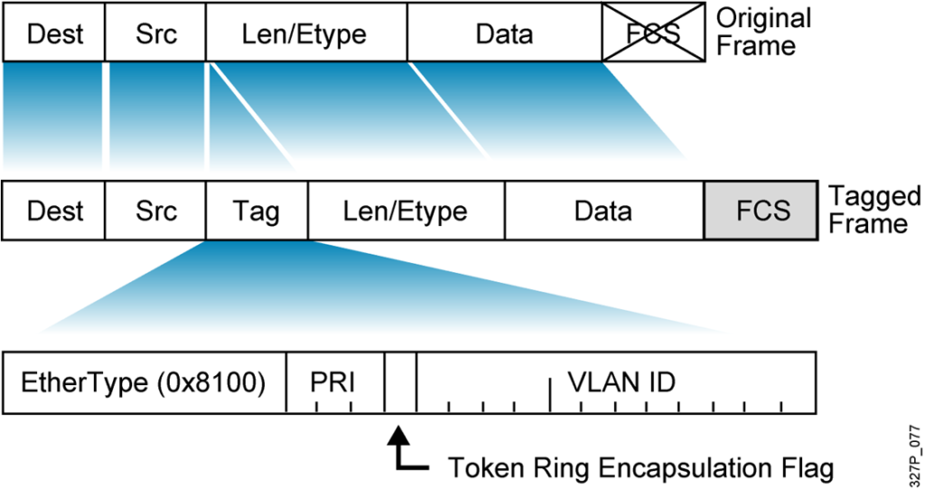
Understanding Native VLANs
VTP Features
VTP Modes

-
- Create VLANs
- Modify VLANs
- Delete VLANs
- Sends and forwards advertisements
- Synchronizes
- Cannot create, change, or delete VLANs
- Sends and forwards advertisements
- Synchronizes
- Create local VLANs only
- Modify local VLANs only
- Delete local VLANs only
- Forwards advertisements
- Does not synchronize
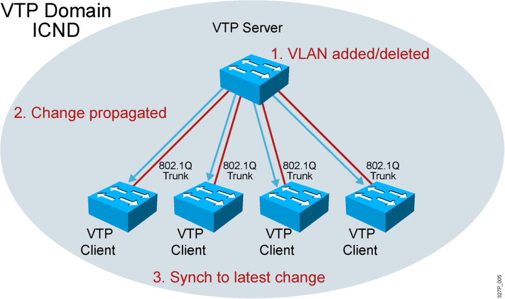
VTP Operation

- VTP advertisements are sent as multicast frames.
- VTP servers and clients are synchronized to the latest revision number.
- VTP advertisements are sent every 5 minutes or when there is a change.
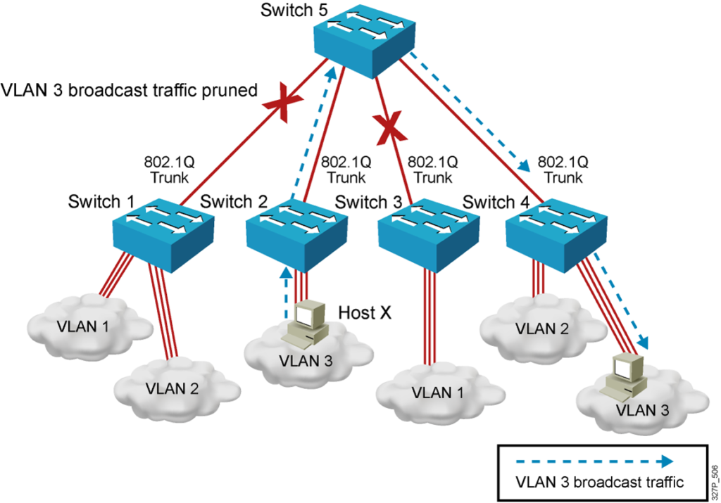
VTP Pruning
Configuring VLANs and Trunks
1.Configure and verify VTP.
2.Configure and verify 802.1Q trunks.
3.Create or modify a VLAN on the VTP server switch.
4.Assign switch ports to a VLAN and verify.
5.Execute adds, moves, and changes.
6.Save the VLAN configuration.
VTP Configuration Guidelines
- VTP defaults for the Cisco Catalyst switch:
– VTP domain name: None
– VTP mode: Server mode
– VTP pruning: Enabled or disabled (model specific)
– VTP password: Null
– VTP version: Version 1
- A new switch can automatically become part of a domain once it receives an advertisement from a server.
- A VTP client can overwrite a VTP server database if the client has a higher revision number.
- A domain name cannot be removed after it is assigned; it can only be reassigned.
All switches in a VTP domain must run the same VTP version.
The password entered with a domain name should be the same for all switches in the domain. If you configure a VTP password, the management domain will not function properly if you do not assign the management domain password to each switch in the domain.
A VTP version 2-capable switch can operate in the same VTP domain as a switch running VTP version 1, provided version 2 is disabled on the version 2-capable switch (version 2 is disabled by default).
Do not enable VTP version 2 on a switch unless all of the switches in the same VTP domain are version 2-capable. When you enable version 2 on a switch, all of the version 2-capable switches in the domain must have version 2 enabled. If there is a version 1-only switch, it will not exchange VTP information with switches with version 2 enabled.
If there are Token Ring networks in your environment, you must enable VTP version 2 for Token Ring VLAN switching to function properly.
Enabling or disabling VTP pruning on a VTP server enables or disables VTP pruning for the entire management domain.
In the lab, all the switches are set to VTP transparent mode.
Creating a VTP Domain
SwitchX# configure terminal
SwitchX(config)# vtp mode [ server | client | transparent ]
SwitchX(config)# vtp domain domain-name
SwitchX(config)# vtp password password
SwitchX(config)# vtp pruning
SwitchX(config)# end
VTP Configuration and Verification Example
SwitchX(config)# vtp domain ICND
Changing VTP domain name to ICND
SwitchX(config)# vtp mode transparent
Setting device to VTP TRANSPARENT mode.
SwitchX(config)# end
SwitchX# show vtp status
VTP Version : 2
Configuration Revision : 0
Maximum VLANs supported locally : 64
Number of existing VLANs : 17
VTP Operating Mode : Transparent
VTP Domain Name : ICND
VTP Pruning Mode : Disabled
VTP V2 Mode : Disabled
VTP Traps Generation : Disabled
MD5 digest : 0x7D 0x6E 0x5E 0x3D 0xAF 0xA0 0x2F 0xAA
Configuration last modified by 10.1.1.4 at 3-3-93 20:08:05
SwitchX#
802.1Q Trunking Issues

- Make sure that the native VLAN for an 802.1Q trunk is the same on both ends of the trunk link.
- Note that native VLAN frames are untagged.
- A trunk port cannot be a secure port.
- All 802.1Q trunking ports in an EtherChannel group must have the same configuration.
Configuring 802.1Q Trunking
SwitchX(config-if)#
switchport mode {access | dynamic {auto | desirable} | trunk}
- Configures the trunking characteristics of the port
SwitchX(config-if)#
switchport mode trunk
- Configures the port as a VLAN trunk
Verifying a Trunk
SwitchX# show interfaces interface [switchport | trunk]
SwitchX# show interfaces fa0/11 switchport
Name: Fa0/11
Switchport: Enabled
Administrative Mode: trunk
Operational Mode: down
Administrative Trunking Encapsulation: dot1q
Negotiation of Trunking: On
Access Mode VLAN: 1 (default)
Trunking Native Mode VLAN: 1 (default)
. . .
SwitchX# show interfaces fa0/11 trunk
Port Mode Encapsulation Status Native vlan
Fa0/11 desirable 802.1q trunking 1
Port Vlans allowed on trunk
Fa0/11 1-4094
Port Vlans allowed and active in management domain
Fa0/11 1-13
( Layer 2 of 2, Note: The Catalyst 1900,at the time of the beta, only supports ISL trunking. It does not support 802.1Q trunking.)
VLAN Creation Guidelines
- The maximum number of VLANs is switch-dependent.
- Most Cisco Catalyst desktop switches support 128 separate spanning-tree instances, one per VLAN.
- VLAN 1 is the factory default Ethernet VLAN.
- Cisco Discovery Protocol and VTP advertisements are sent on VLAN 1.
- The Cisco Catalyst switch IP address is in the management VLAN (VLAN 1 by default).
- If using VTP, the switch must be in VTP server or transparent mode to add or delete VLANs.
- ( Note: In the ICND lab, all the switches and routers are in VLAN1. The core server and the core router are in multiple VLANs. Each workgroup PC is on an unique VLAN.)
Adding a VLAN
SwitchX# configure terminal
SwitchX(config)# vlan 2
SwitchX(config-vlan)# name switchlab99
Verifying a VLAN
SwitchX# show vlan [brief | id vlan-id || name vlan-name]
SwitchX# show vlan id 2
VLAN Name Status Ports
—- ——————————– ——— ——————————-
2 switchlab99 active Fa0/2, Fa0/12
VLAN Type SAID MTU Parent RingNo BridgeNo Stp BrdgMode Trans1 Trans2
—- —– ———- —– —— —— ——– —- ——– —— ——
2 enet 100002 1500 – – – – – 0 0
. . .
SwitchX#
Layer 2 of 2
Note:
Type: Default is Ethernet (other types are FDDI and Token Ring).
SAID: Is used for FDDI trunking.
MTU: Default is 1500 for Ethernet VLAN.
STP: The 1900 only supports 802.1d Spanning-Tree Protocol. It does not support DEC or IBM Spanning-Tree Protocol. Routers support all three Spanning-Tree Protocol standards.
Other parameters: Used for Token Ring or FDDI VLANs.
Assigning Switch Ports to a VLAN
SwitchX(config-if)#
switchport access [vlan vlan# | dynamic]
SwitchX# configure terminal
SwitchX(config)# interface range fastethernet 0/2 – 4
SwitchX(config-if)# switchport access vlan 2
SwitchX# show vlan
VLAN Name Status Ports
—- ——————————– ——— ———————-
1 default active Fa0/1
2 switchlab99 active Fa0/2, Fa0/3, Fa0/4
Layer 2 of 2
Note: In the lab, we will only be configuring static VLAN membership.
Verifying VLAN Membership
SwitchX# show vlan brief
SwitchX# show vlan brief
VLAN Name Status Ports
—- ——————————– ——— ——————————-
1 default active Fa0/1
2 switchlab99 active Fa0/2, Fa0/3, Fa0/4
3 vlan3 active
4 vlan4 active
1002 fddi-default act/unsup
1003 token-ring-default act/unsup
VLAN Name Status Ports
—- ——————————– ——— ——————————-
1004 fddinet-default act/unsup
1005 trnet-default act/unsup
Layer 2 of 2
Emphasize: Port 1 = e0/1, ……. AUI = e0/25, A = fa 0/26, B = fa 0/27
Verifying VLAN Membership (Cont.)
SwitchX(config-if)#
show interfaces interface switchport
SwitchX# show interfaces fa0/2 switchport
Name: Fa0/2
Switchport: Enabled
Administrative Mode: dynamic auto
Operational Mode: static access
Administrative Trunking Encapsulation: dot1q
Operational Trunking Encapsulation: native
Negotiation of Trunking: On
Access Mode VLAN: 2 (switchlab99)
Trunking Native Mode VLAN: 1 (default)
— output omitted —-
Layer 2 of 2
Note: In the lab, we will only be configuring static VLAN membership.
Executing Adds, Moves, and Changes for VLANs
- When using VTP, the switch must be in VTP server or transparent mode to add, change, or delete VLANs.
- When you make VLAN changes from a switch in VTP server mode, the change is propagated to other switches in the VTP domain.
- Changing VLANs typically implies changing IP networks.
- After a port is reassigned to a new VLAN, that port is automatically removed from its previous VLAN.
- When you delete a VLAN, any ports in that VLAN that are not moved to an active VLAN will be unable to communicate with other stations.
Summary
- A poorly designed network has increased support costs, reduced service availability, and limited support for new applications and solutions.
- VLANs provide segmentation and organizational flexibility.
- Ethernet trunks carry the traffic of multiple VLANs over a single link and allow you to extend VLANs across an entire network.
- VTP is a Layer 2 messaging protocol that maintains VLAN configuration consistency.
