4.5.1 Packet Tracer – Packet Tracer Skills Integration Challenge Answers
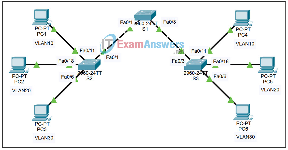
Topology

Addressing Table
| Device | Interface | IP Address | Subnet Mask | Default Gateway |
|---|---|---|---|---|
| S1 | VLAN 99 | 172.17.99.31 | 255.255.255.0 | 172.17.99.1 |
| S2 | VLAN 99 | 172.17.99.32 | 255.255.255.0 | 172.17.99.1 |
| S3 | VLAN 99 | 172.17.99.33 | 255.255.255.0 | 172.17.99.1 |
| PC1 | NIC | 172.17.10.21 | 255.255.255.0 | 172.17.10.1 |
| PC2 | NIC | 172.17.20.22 | 255.255.255.0 | 172.17.20.1 |
| PC3 | NIC | 172.17.30.23 | 255.255.255.0 | 172.17.30.1 |
| PC4 | NIC | 172.17.10.24 | 255.255.255.0 | 172.17.10.1 |
| PC5 | NIC | 172.17.20.25 | 255.255.255.0 | 172.17.20.1 |
| PC6 | NIC | 172.17.30.26 | 255.255.255.0 | 172.17.30.1 |
Learning Objectives
- Configure and verify basic device configurations
- Configure and verify port security
- Configure VTP
- Configure trunking
- Configure VLANs
- Assign VLANs to ports
- Verify end-to-end connectivity
Introduction:
In this activity, you will configure switches including basic configuration, port security, trunking and VLANs. You will use VTP to advertise the VLAN configurations to other switches.
Task 1: Configure and Verify Basic Device Configurations
Step 1. Configure basic commands.
Configure each switch with the following basic commands. Packet Tracer will only grade the hostname command.
- Hostname on S1
- Banner
- Enable secret password
- Line configurations
- Service encryption
Step 2. Configure the management VLAN interface on S1, S2, and S3.
Create and enable interface VLAN 99 on each switch. Use the addressing table for address configuration.
Step 3. Verify PCs on the same subnet can ping each other.
The PCs are already configured with correct addressing. Create Simple PDUs to test connectivity between devices on the same subnet.
Step 4. Check results.
Your completion percentage should be 15%. If not, click Check Results to see which required components are not yet completed.
Task 2: Configure and Verify Port Security
Step 1. Configure all access links with port security.
Normally you configure port security on all access ports or shutdown the port if it is not in use. Use the following policy to establish port security just on the ports used by the PCs.
- Set the port to access mode.
- Enable port security.
- Allow only 1 MAC address.
- Configure the first learned MAC address to “stick” to the configuration.
- Set the port to shutdown if there is a security violation.
- Force the switches to learn the MAC addresses by sending pings across all three switches.
NOTE: Only enabling port security is graded by Packet Tracer. However, all the port security tasks listed above are required to complete this activity.
Step 2. Test port security.
- Connect PC2 to PC3’s port and connect PC3 to PC2’s port.
- Send pings between PCs on the same subnet.
- The ports for PC2 and PC3 should shutdown.
Step 3. Verify ports are “err-disabled” and that a security violation has been logged.
Step 4. Reconnect PCs to correct port and clear port security violations.
- Connect PC2 and PC3 back to the correct ports.
- Clear the port security violation.
- Verify PC2 and PC3 can now send pings across S2.
Step 5. Check results.
Your completion percentage should be 55%. If not, click Check Results to see which required components are not yet completed.
Task 3: Configure VTP
Step 1. Configure the VTP mode on all three switches.
Configure S1 as the server. Configure S2 and S3 as clients.
Step 2. Configure the VTP domain name on all three switches.
Use CCNA as the VTP domain name.
Step 3. Configure VTP domain password on all three switches.
Use cisco as the VTP domain password.
Step 4. Check results.
Your completion percentage should be 70%. If not, click Check Results to see which required components are not yet completed.
Task 4: Configure Trunking
Step 1. Configure trunking on S1, S2, and S3.
Configure the appropriate interfaces in trunking mode and assign VLAN 99 as the native VLAN.
Step 2. Check results.
Your completion percentage should be 83%. If not, click Check Results to see which required components are not yet completed.
Task 5: Configure VLANs
Step 1. Create the VLANs on S1.
Create and name the following VLANs on S1 only. VTP will advertise the new VLANs to S1 and S2.
- VLAN 10 Faculty/Staff
- VLAN 20 Students
- VLAN 30 Guest(Default)
- VLAN 99 Management&Native
Step 2. Verify VLANs have been sent to S2 and S3.
Use appropriate commands to verify that S2 and S3 now have the VLANs you created on S1. It may take a few minutes for Packet Tracer to simulate the VTP advertisements.
Step 3. Check results.
Your completion percentage should be 90%. If not, click Check Results to see which required components are not yet completed.
Task 6: Assign VLANs to ports
Step 1. Assign VLANs to access ports on S2 and S3.
Assign the PC access ports to VLANs:
- VLAN 10: PC1 and PC4
- VLAN 20: PC2 and PC5
- VLAN 30: PC3 and PC6
Step 2. Verify VLAN implementation.
Use the appropriate command to verify your VLAN implementation.
Step 3. Check results
Your completion percentage should be 100%. If not, click Check Results to see which required components are not yet completed.
