5.1.3 Packet Tracer – Examining a Redundant Design Answers
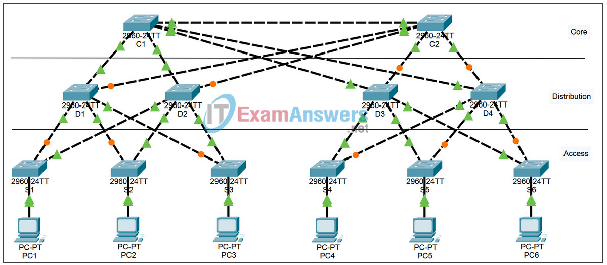
Topology

Learning Objectives
- Check for STP convergence
- Examine the ARP process
- Test redundancy in a switched network
Introduction
In this activity, you will examine how STP operates by default. Switches have been added to the network “out of the box.” Cisco switches can be plugged in and connected to a network without any additional action by the network administrator. Therefore these switches will act according to default settings.
Task 1: Check for STP Convergence
When STP is fully converged, the following conditions exist:
- All PCs have green link lights on the switched ports.
- Access layer switches have one forwarding uplink (green) to a distribution layer switch and a blocking uplink (amber) to a second distribution layer switch.
- Distribution layer switches have one forwarding uplink (green) to a core layer switch and a blocking uplink (amber) to another core layer switch.
Task 2: Examine the ARP Process
Step 1. Switch to Simulation mode.
Step 2. Ping from PC1 to PC6.
Use the Add Simple PDU tool to create a PDU from PC1 to PC6. Be sure ICMP is selected in the Event List Filters. Click Capture/Forward to examine the ARP process as the switched network learns the MAC addresses of PC1 and PC6. Notice that all possible loops are stopped by blocking ports. For example, the ARP request from PC1 travels from S1 to D2 to C1 to D1 and then back to S1. However, because STP is blocking the link between S1 and D1, no loop occurs.
Notice that the ARP reply from PC6 travels back along one path. Why?
Record the loop-free path between PC1 and PC6.
Step 3. Examine the ARP process again.
Examine the ARP process again by pinging between two different PCs.
What part of the path changed from the last set of pings?
Task 3: Test Redundancy in a Switched Network
Step 1. Delete the link between S1 and D2.
Switch to Realtime mode. Delete the link between S1 and D2. It takes some time for STP to converge and establish a new, loop-free path. Because only S1 is affected, watch for the amber light on the link between S1 and D1 to change to green.
Step 2. Ping between PC1 and PC6.
After the link between S1 and D1 is active (indicated by a green light), switch to Simulation mode and ping between PC1 and PC6 again.
Record the new loop-free path.
Step 3. Delete link between C1 and D3.
Switch to Realtime mode. Notice that the links between D3 and D4 to C2 are amber. Delete the link between C1 and D3. It will take some time for STP to converge and establish a new, loop-free path. Watch the amber links on D3 and D4. You can switch between Simulation mode and Realtime mode to accelerate the process.
Which link is now the active link to C2?
Step 4. Ping between PC1 and PC6.
Switch to Simulation mode and ping between PC1 and PC6.
Record the new loop-free path.
Step 5. Delete D4.
Switch to Realtime mode. Notice that S4, S5, and S6 are all forwarding traffic to D4. Delete D4. It takes some time for STP to converge and establish a new, loop-free path. Watch for the links between S4, S5, and S6 to D3 transition to forwarding (green). All three switches should now be forwarding to D3.
Step 6. Ping between PC1 and PC6.
Switch to Simulation mode and ping between PC1 and PC6.
Record the new loop-free path.
What is unique about the new path that you have not seen before?
Step 7. Delete C1.
Switch to Realtime mode. Notice that D1 and D2 are both forwarding traffic to C1. Delete C1. It takes some time for STP to converge and establish a new, loop-free path. Watch for the links between D1 and D2 to C2 to transition to forwarding (green). Once converged, both switches should now be forwarding to C2.
Step 8. Ping between PC1 and PC6.
Switch to Simulation mode and ping between PC1 and PC6.
Record the new loop-free path.
