Packet Tracer – Create Realistic Structured Cabling in the Physical Workspace and Cabling Devices in a Rack Answers (Answers Version)
Topology
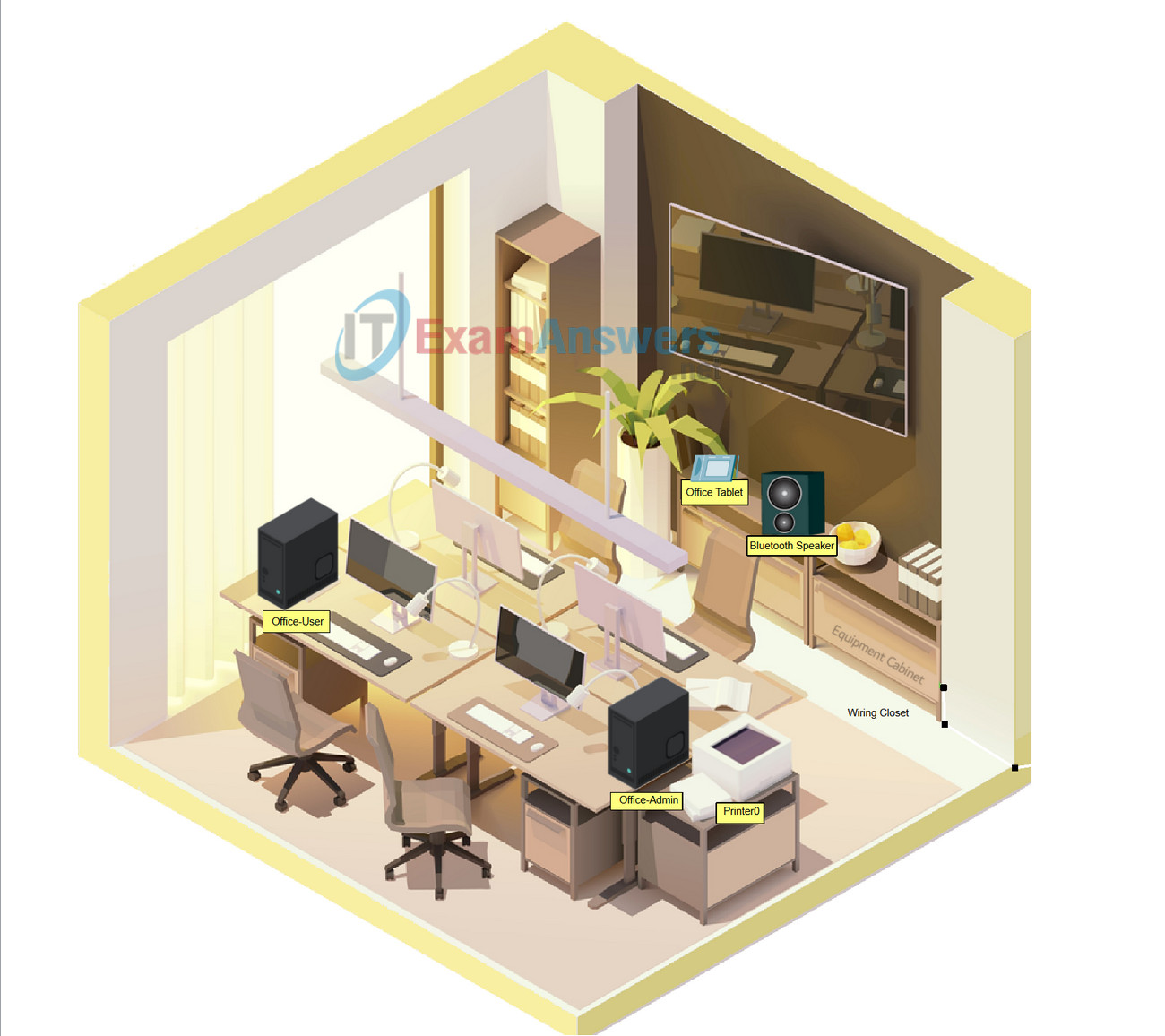
Objectives
In this activity, you will install a patch panel and a wall mount. You will then use these to connect network devices in the office to the equipment in the wiring closet.
- Part 1: Install a Patch Panel in the Wiring Closet
- Part 2: Attach a Wall Mount in the Office
- Part 3: Connect an Additional Wall Mount and Cables
Required Resources
- Latest Packet Tracer version
Instructions
Part 1: Install a Patch Panel in the Wiring Closet
Step 1: Install a patch panel in the Rack
a. Click the Equipment Cabinet to access a simulated Wiring Closet.
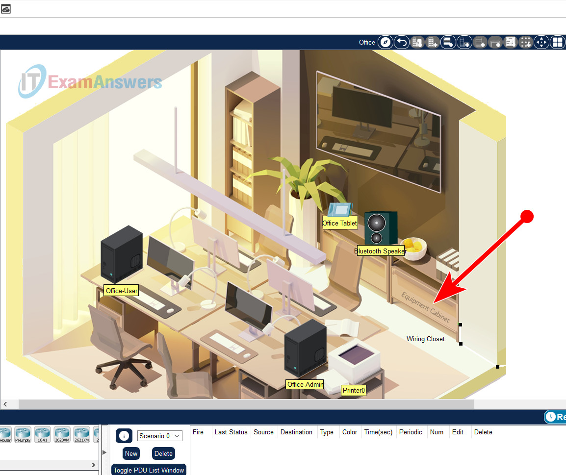
Equipment Cabinet
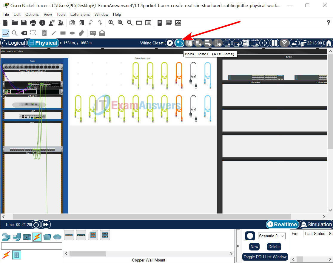
You can also click the Back level (Alt+Left) to go back.
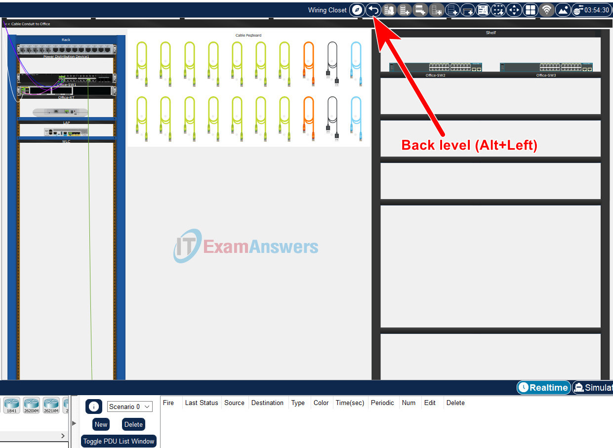
b. To install a patch panel, click Connections in the Device-Type Selection Box, and then click Structured Cabling.
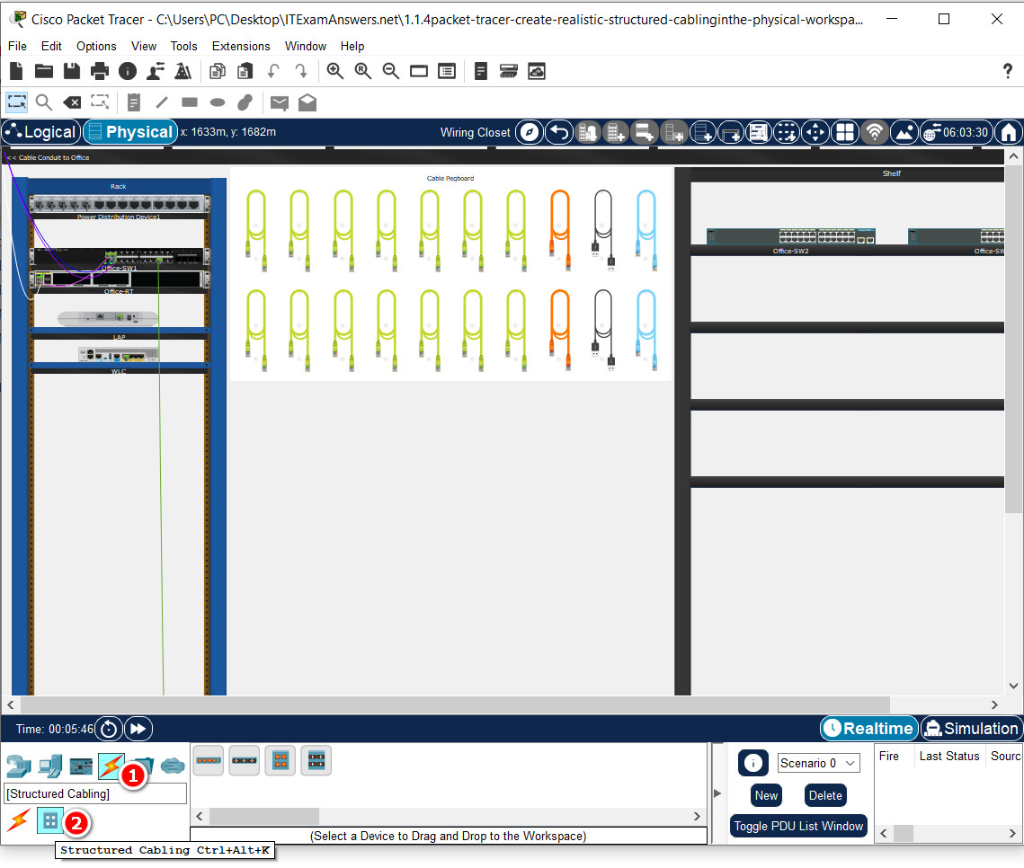
Structured Cabling
c. In the Device-Specific Selection Box, click the first option, which is Copper Patch Panel.
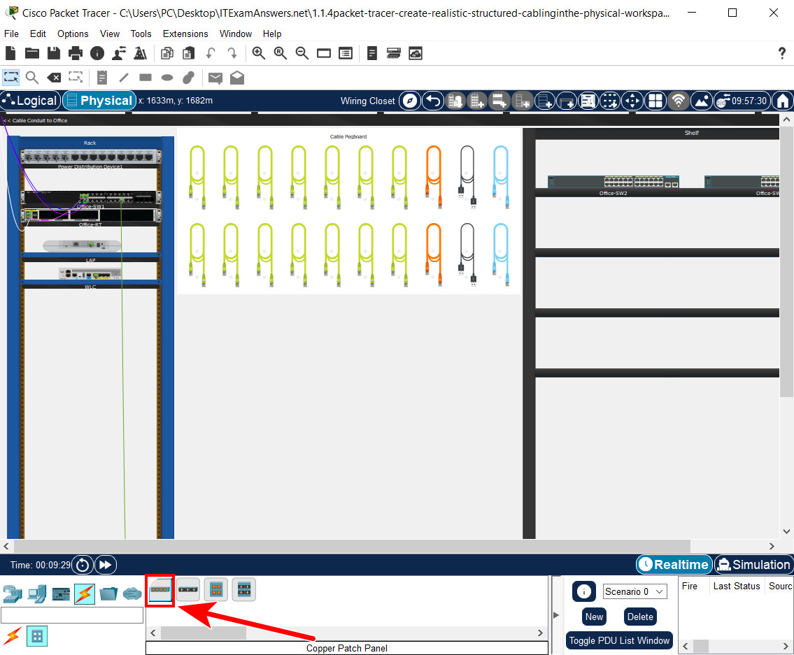
Copper Patch Panel
d. Click a desired location in the Rack to install the patch panel in the rack.
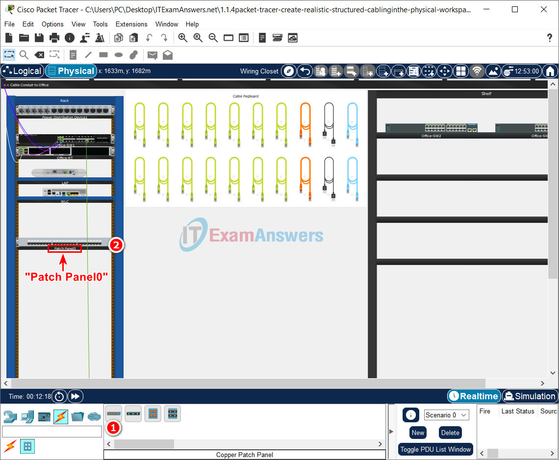
Note: For accurate grading, make sure the name of the patch panel is Patch Panel0.
Step 2: Connect the Office-SW1 to the patch panel.
a. From the Cable Pegboard, select a Copper Straight-Through cable.
b. On the switch Office-SW1, click the GigabitEthernet 1/0/13 port. Now locate and click Jack13 on the Patch Panel0.
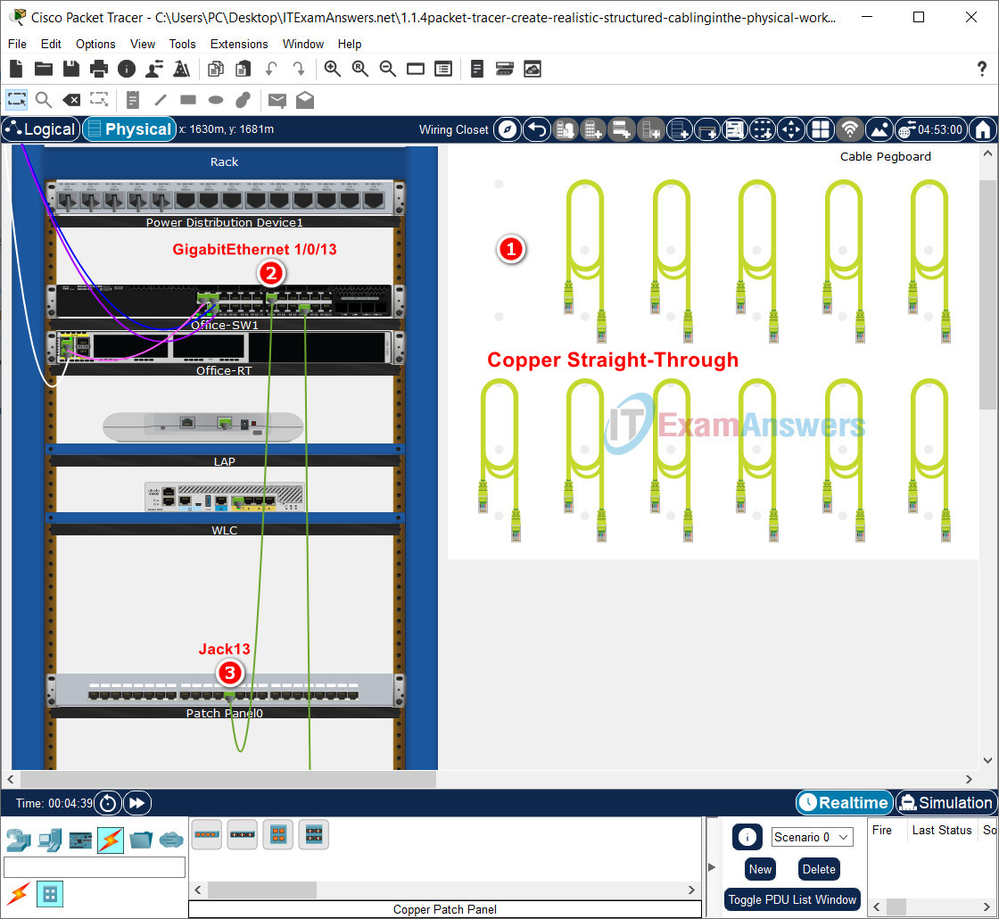
Note: Recall that you can right click the switch and the patch panel, select Inspect Front, and then zoom in to better locate the desired ports. You can also use the global Zoom In tool on the tool bar.
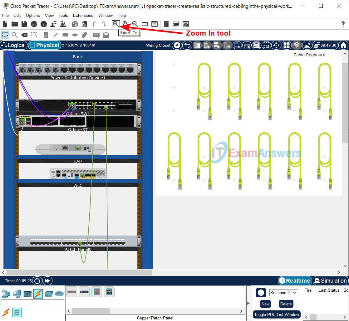
Zoom In tool on the tool bar Packet Tracer
c. Use the following table to finish the connections between the Patch Panel0 and Office-SW-1.
| Office-SW1 | Patch Panel0 |
|---|---|
| G1/0/13 | Jack13 |
| G1/0/14 | Jack14 |
| G1/0/15 | Jack15 |
| G1/0/16 | Jack16 |
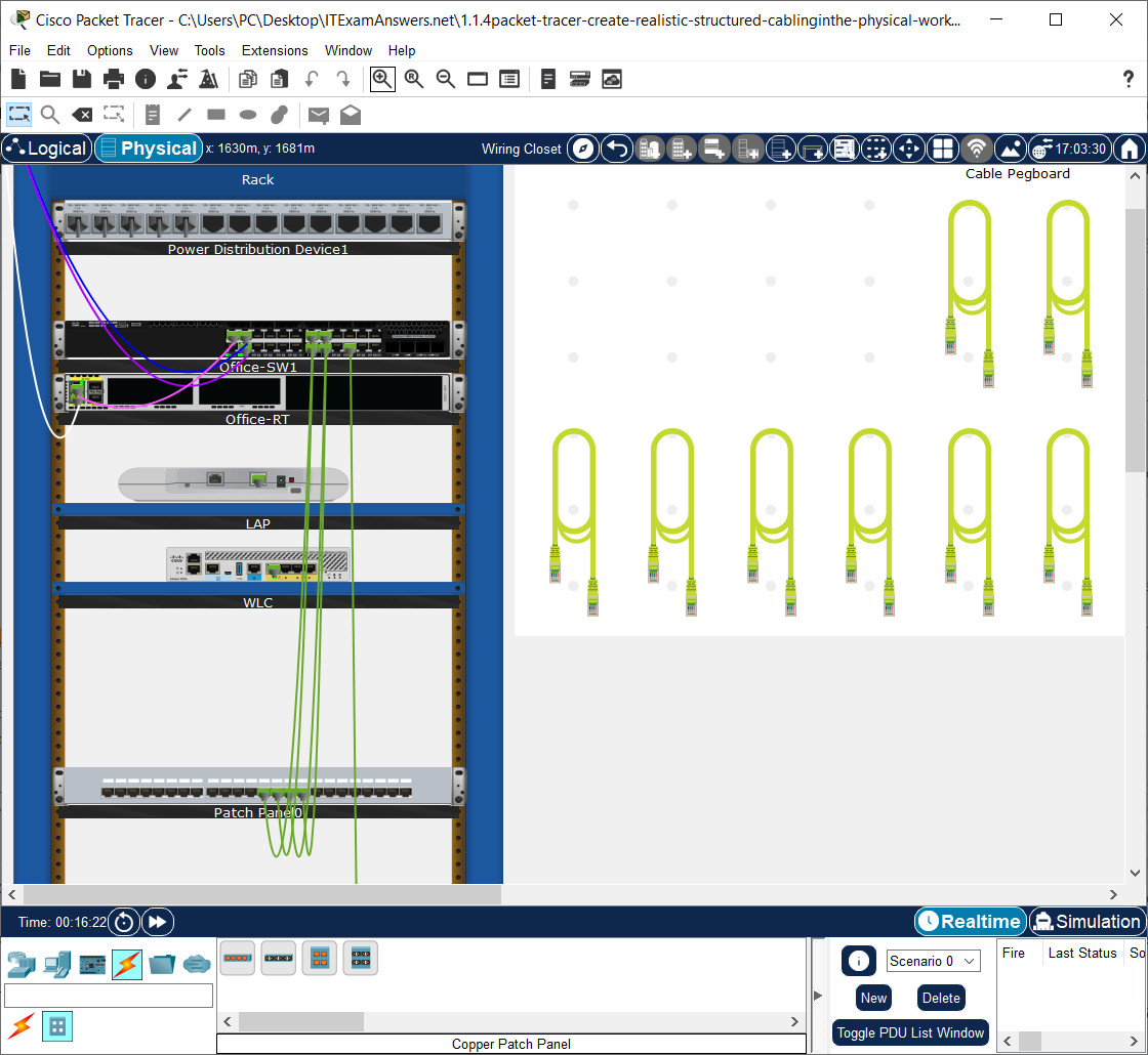
d. If desired, you could also color code the cables in the rack. Right-click the desired cable, select Color Cable. Select or create the desired color, and click OK.
e. If you do not like the cables dangling, you can organize them. Right-click any white space in the rack and select Manage All Cables on Rack. Now all your cables are organized on the rack.
f. Click Back level (Alt-Left) to return to the Office.
Part 2: Attach a Wall Mount in the Office
Step 1: Install a wall mount.
a. To install a wall mount, click Connections in the Device-Type Selection Box, and then click Structured Cabling.
b. In the Device-Specific Selection Box, click Copper Wall Mount.
c. Click the desired location on the wall next to the Equipment Cabinet.
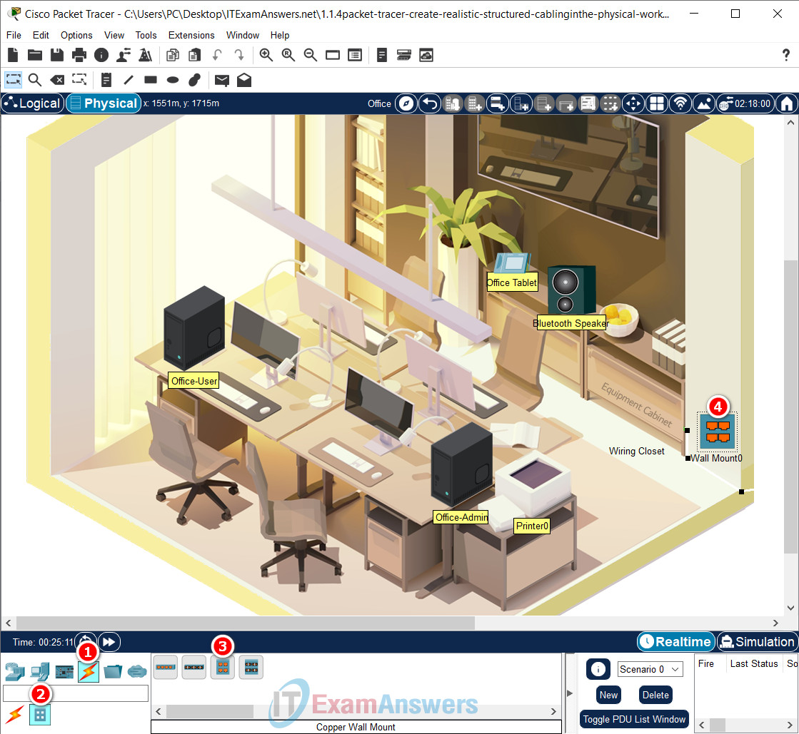
nstall a Copper Wall Mount
Note: For accurate grading, make sure the name of the wall mount is Wall Mount0.
d. In the Device-Type Selection Box, click Connections, and then click Copper Straight-Through cable.
e. Click Wall Mount0 and select PunchDown1. Then click the Equipment Cabinet (Wiring Closet) and select Rack > Patch Panel0 > Punchdown13.
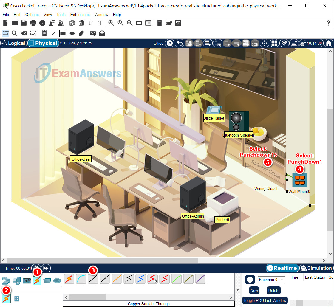
f. Repeat for the rest of the available punchdowns on Wall Mount0.
| Wall Mount (Next to Equipment Cabinet) | Patch Panel |
|---|---|
| Punchdown1 | Punchdown13 |
| Punchdown2 | Punchdown14 |
| Punchdown3 | Punchdown15 |
| Punchdown4 | Punchdown16 |
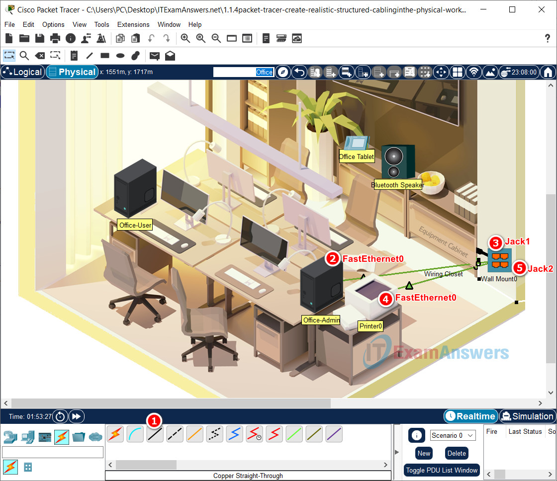
g. Connect the PC Office-Admin and Printer0 to any available jacks in the wall mount using Copper Straight-Through cables. After a minute or two, both devices will receive IP addressing information from the DHCP service running on the Office-Server inside the Equipment Closet.
- Using Copper Straight-Through cables, on the Office-Admin, click the FastEthernet0 port. Now locate and click Jack1 on the Wall Mount0.
- Using Copper Straight-Through cables, on the Printer0, click the FastEthernet0 port. Now locate and click Jack2 on the Wall Mount0.
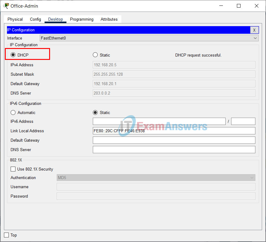
Enable DHCP on Office-Admin PC:
- Click the Office-Admin
- Go to: Desktop tab > IP Configuration > Click DHCP
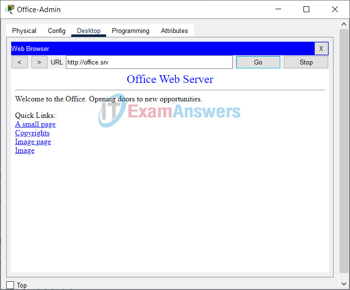
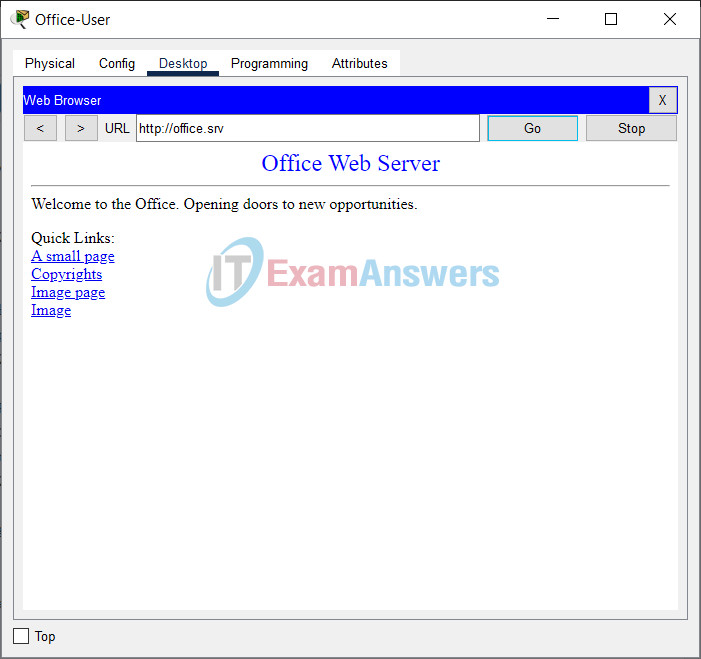
h. Verify connectivity by navigating to the web site http://office.srv. Click Office-Admin > Desktop > Web Browser. Enter office.srv in the URL field. This may take up to a minute. You can click Go to refresh the web page request.
Step 2: Organize the cables.
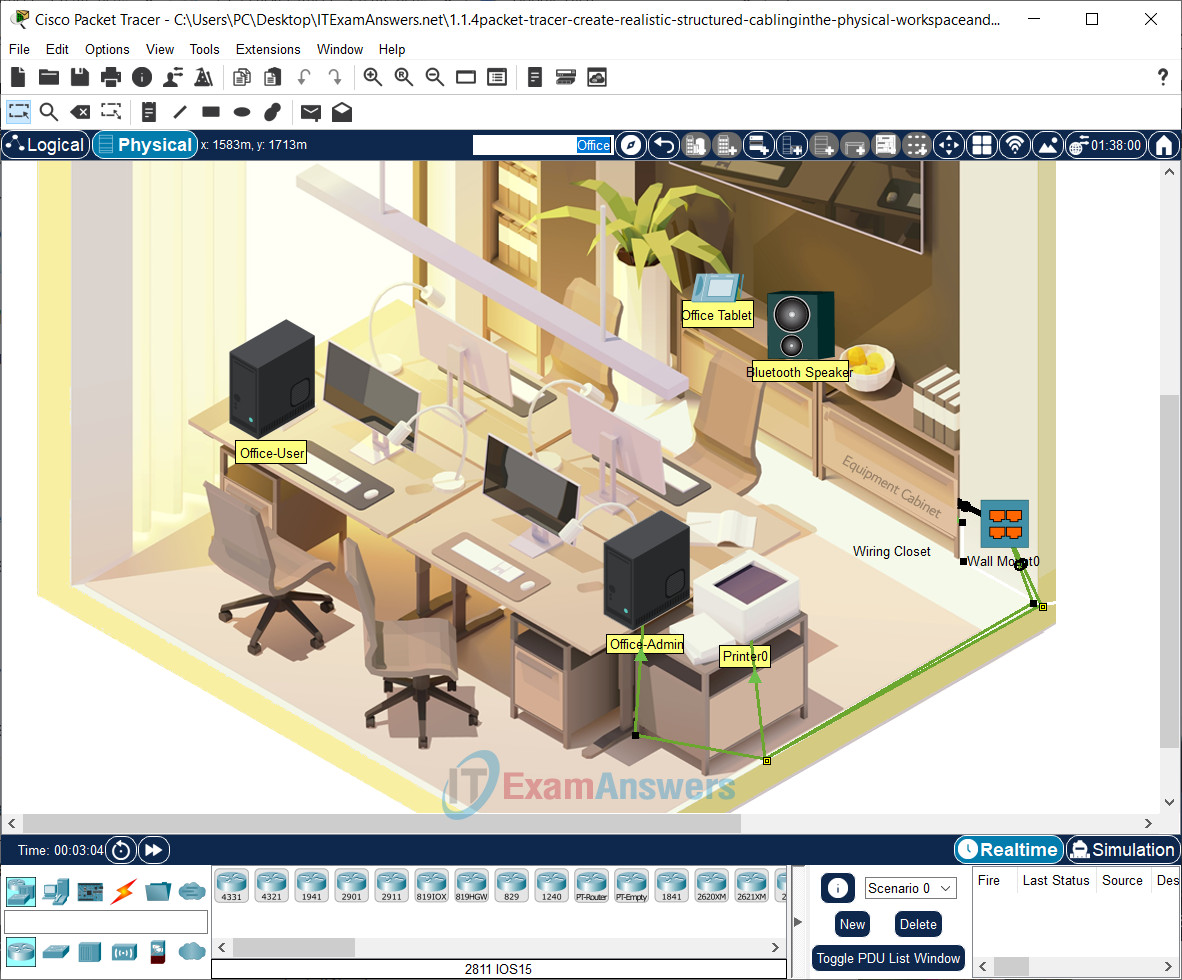
In the Physical mode, you can organize the cables so that they are spanning across the entire room.
a. Right-click the desired cable, select Create BendPoint.
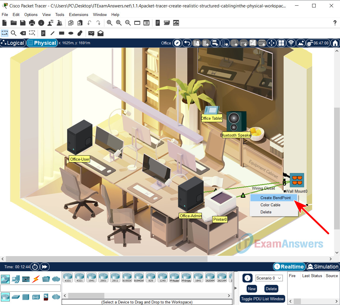
b. Drag the black square to the wall. Continue to create bendpoints and drag the bend points into the walls or floor until the cable no longer goes across the middle of the room
Using the bendpoints has the same effects as running the cables into the walls in an office.
c. Repeat the steps until you are satisfied with the results.
Part 3: Connect an Additional Wall Mount and Cables
Now that you have connected AdminOffice and Printer0 to the network, connect more cables to the patch panel, add another wall mount, and connect the Office-User PC.
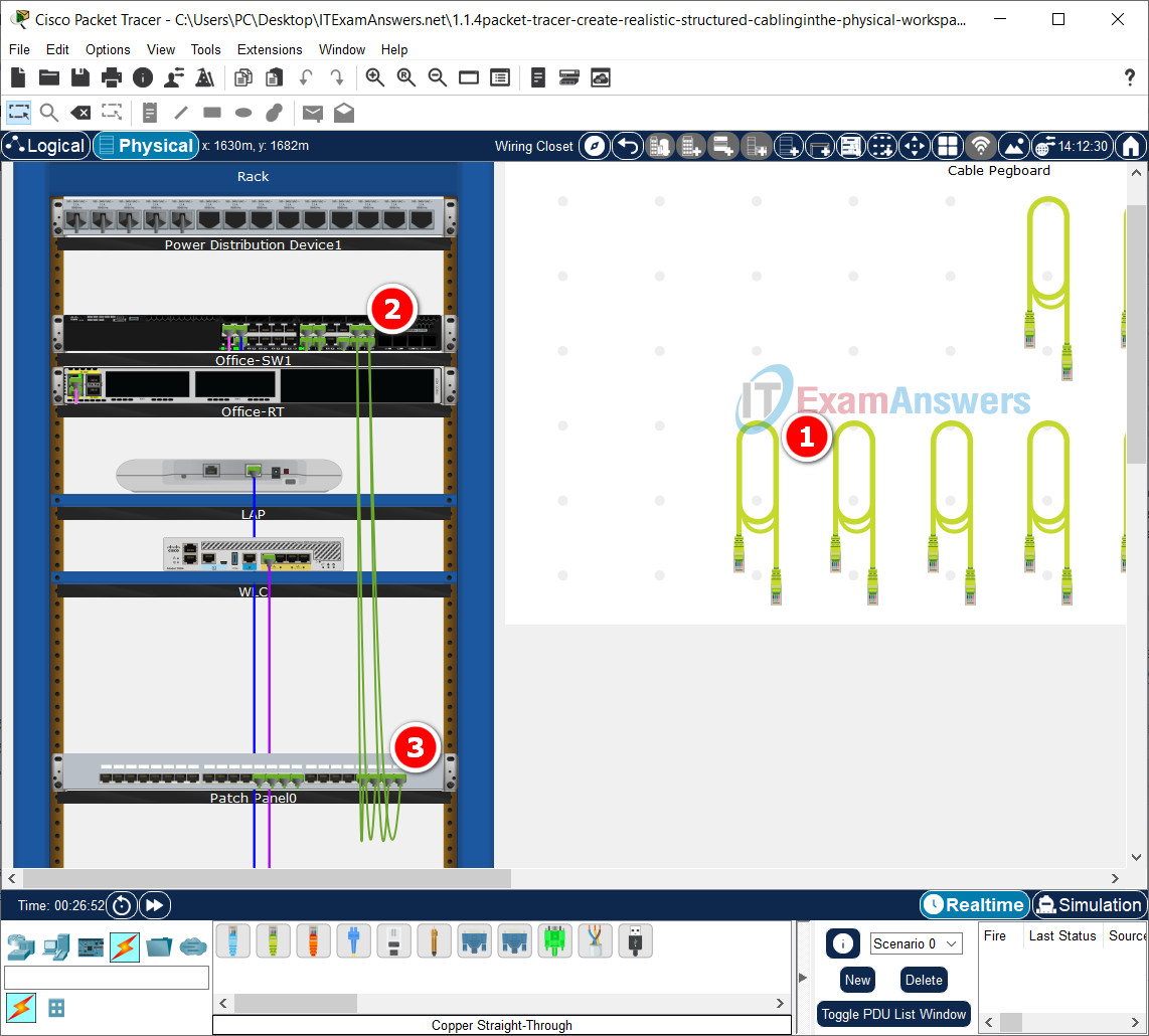
a. Return to the Equipment Closet and make the following connections:
| Office-SW1 | Patch Panel0 |
|---|---|
| G1/0/21 | Jack21 |
| G1/0/22 | Jack22 |
| G1/0/23 | Jack23 |
| G1/0/24 | Jack24 |
Click the Equipment Cabinet to access a simulated Wiring Closet:
- From the Cable Pegboard, select a Copper Straight-Through cable.
- On the switch Office-SW1, click the G1/0/21 port. Now locate and click Jack21 on the Patch Panel0.
- Repeat the above steps to make the remaining connections.
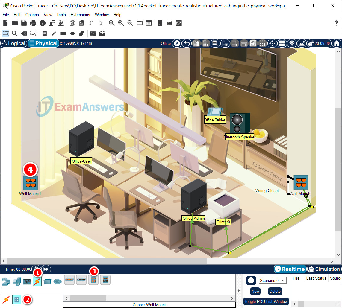
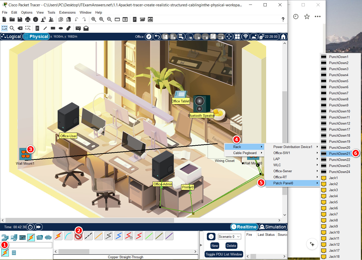
b. In the Office, add another Wall Mount next to the window and connect the wall mount to the patch panel using the following connections.
Note: For accurate grading, make sure the name of the wall mount is Wall Mount1.
| New Wall Mount (Next to Window) | Patch Panel0 |
|---|---|
| Punchdown1 | Punchdown21 |
| Punchdown2 | Punchdown22 |
| Punchdown3 | Punchdown23 |
| Punchdown4 | Punchdown24 |
- Click Connections > Structured Cabling > Copper Wall Mount
- Click the desired location on the wall next to the window.
c. Connect the Office-User PC to your new wall mount.
Using Copper Straight-Through cables, on the Office-User, click the FastEthernet0 port. Now locate and click Jack1 on the Wall Mount1.
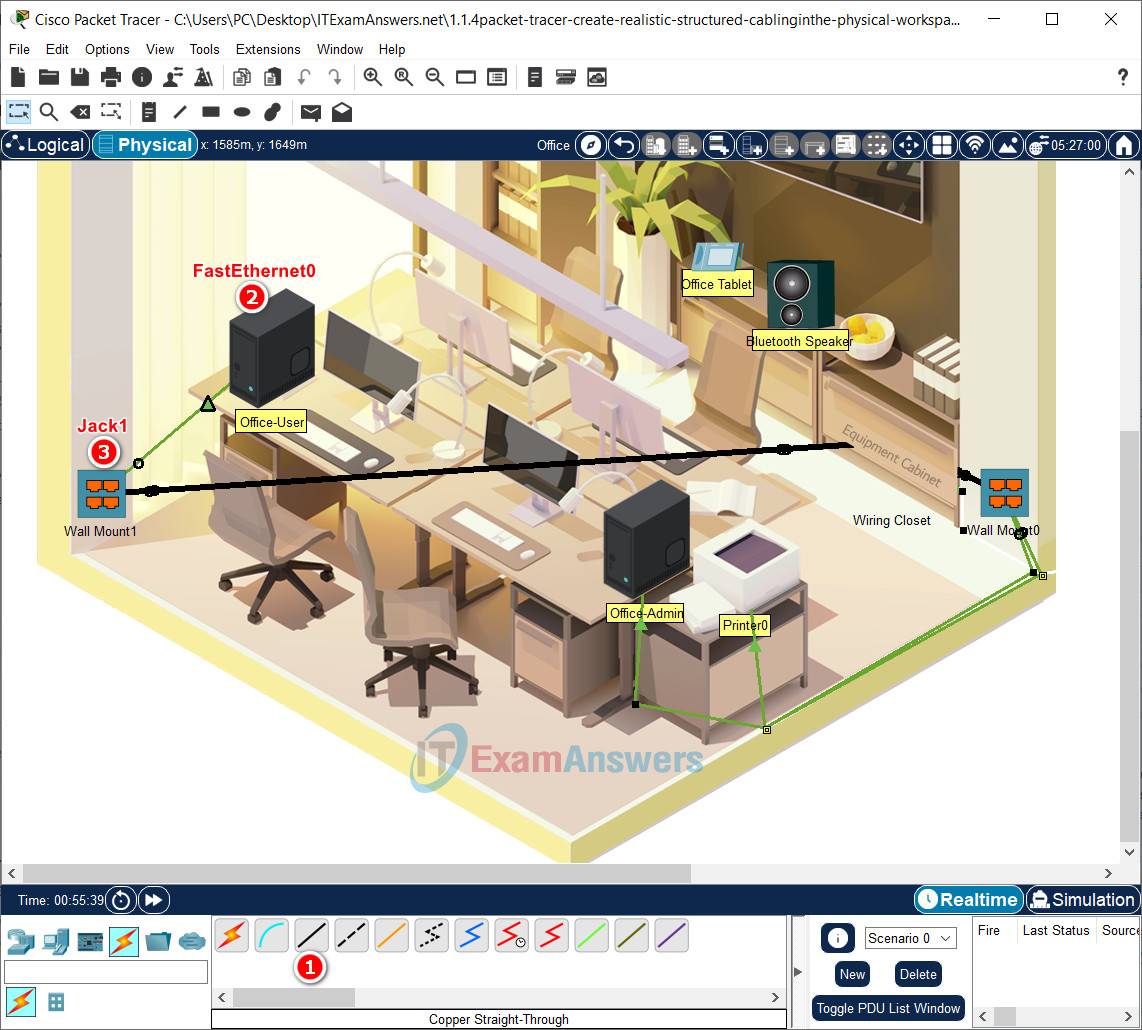
Enable DHCP on Office-User PC:
- Click the Office-User
- Go to: Desktop tab > IP Configuration > Click DHCP
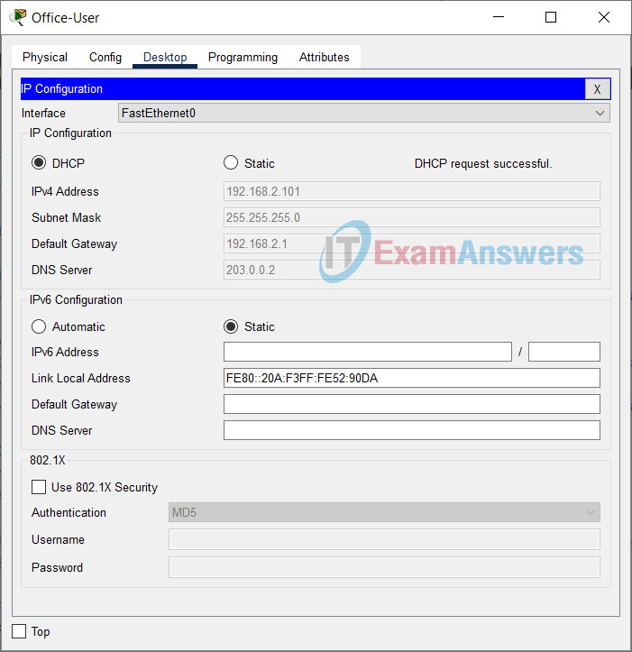
d. After a minute or two, verify the Office-User PC received IP addressing information and then verify connectivity to the web site office.srv.
e. If desired, create bend points in the cables and organize them.
