Packet Tracer – Examine Packets in the Small Office Answers (Instructor Version)
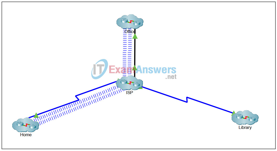
Topology

Objectives
- Part 1: Create a Simple PDU in Simulation Mode
- Part 2: View Contents of PDUs
- Part 3: Create a Complex PDU in Simulation Mode
Background / Scenario
In this Packet Tracer activity, you will use the Simulation mode to create PDUs to explore network functionality.
Note: Simulation mode does not work in Physical mode; therefore, Physical mode is locked.
Instructions
Part 1: Create a Simple PDU in Simulation Mode
Step 1: Enter the Office network.
Click Office to view the logical network for the Office.
Step 2: Enter Simulation mode.
Click the Simulation mode icon in the bottom-right corner of the Packet Tracer window to open the Simulation panel. This pauses all network traffic that occurs in Realtime mode.
Note: A pop-up window will open stating “Intercity is locked.” Click on the okay tab in the window to close it. You will need to do this before continuing. You can center the Packet Tracer by scrolling the bar at the bottom of the Packet Tracer activity area.
Step 3: Create a simple PDU that sends a ping from Office-Admin to Printer0.
a. Click Add Simple PDU in the top toolbar. It looks like a closed envelope. The curser will change to an envelope with a plus sign when you move the cursor into the Packet Tracer activity area.
b. Click Office-Admin first so that it will become the source of the ping, and then click Printer0 so that it will become the destination.
Step 4: Observe traffic moving through the network.
a. In the Play Controls area of the Simulation Panel, directly below the Reset Simulation button, click Capture/Forward, which is the button directly to the right of the Play button.
b. Observe the traffic move through the network each time the button is clicked. Notice also that each time Capture/Forward is clicked, sent packets are displayed in the Event List in the Simulation Panel.
c. Continue clicking Capture/Forward until the return ICMP packet makes it back to Office-Admin. Continue clicking on the Capture/Forward button quickly several times until you get a pop-up window that states “Buffer Full-Cisco packet Tracer”.
d. When the Buffer Full message pops up, click View Previous Events. If you accidentally click Clear Event List, click Reset Simulation and return to the beginning of this step.
Part 2: View Contents of PDUs
Step 1: Use the event list to see PDU information.
View the information of the first ICMP PDU packet from the PC.
a. In the Event List window, find the Type column. You may need to expand the width of the Simulation Panel. To do so, click and drag the vertical bar on the left of the window.
b. In the Type column, click the first ICMP packet. This will open the PDU Information at Device: Office-Admin window.
c. Observe the information in the OSI Model tab. Notice that this is an outbound Layer 3 PDU and the source and destination IPv4 addresses are shown.
d. Click the Outbound PDU Details tab. Notice that this tab shows details of the protocol headers.
e. Close the PDU Information at Device: Office-Admin window.
f. Explore the contents of other PDUs that are listed in the Simulation Panel and review the information that is available in each.
Step 2: Delete the simple PDU.
Double click the Delete button in the Event Simulation pane at the bottom of the Packet Tracer window. Notice that this removes the simple PDU and clears out all PDUs from the Event List in the Simulation Panel.
Part 3: Create a Complex PDU in Simulation Mode
Step 1: Add a complex PDU to send pings from the PC to the laptop.
a. Click Add Complex PDU in the top toolbar. It looks like an open envelope.
b. Click Office-Admin first so that it will become the source of the ping. The Create Complex PDU window will display. Leave this window open.
c. Click Printer0 so that it will become the destination. Notice that the Destination IP Address field in the Create Complex PDU window is now set to the IPv4 address for Printer0. You can see the IPv4 address for Printer0 by hovering the pointer over it.
Step 2: Configure complex PDU settings to send the pings every 5 seconds.
a. In the Create Complex PDU window, there are many settings which can be customized. Notice that PING is automatically selected as the application for this PDU.
b. The Sequence Number field must be populated with a value. Enter 1234.
c. In the Simulation Settings section, click Periodic, and then set the Interval to 5 seconds.
d. Click Create PDU. The first ICMP packet is now shown in the Event List and a packet icon is shown over Office-Admin.
Step 3: Observe traffic moving through the network.
a. Click Play in the Simulation Panel and watch the traffic move through the network. Notice the PDUs populating the Event List. in the Simulation Panel. A new PDU is created every 5 seconds.
b. Directly below the Play button is a slider. You can drag this right to speed up the animation or left to slow it down.
c. Click Play at any time to stop the simulation.
d. To delete the complex PDU, double click Delete in the Event Simulation pane at the bottom of the Packet Tracer window.
