Packet Tracer – Edit Topologies (Instructor Version)
Topology
Objectives
In this activity, you will install a patch panel and a wall mount. You will then use these to connect network devices in the office to the equipment in the wiring closet.
- Part 1: Add an Additional Switch to the Rack in the Office Network
- Part 2: Connect a PC to the Office Network
- Part 3: Work with Clusters
- Part 4: Add a Second Home Cluster to the Network
Required Resources
- Latest Packet Tracer version
Instructions
Part 1: Add an Additional Switch to the Rack in the Office Network
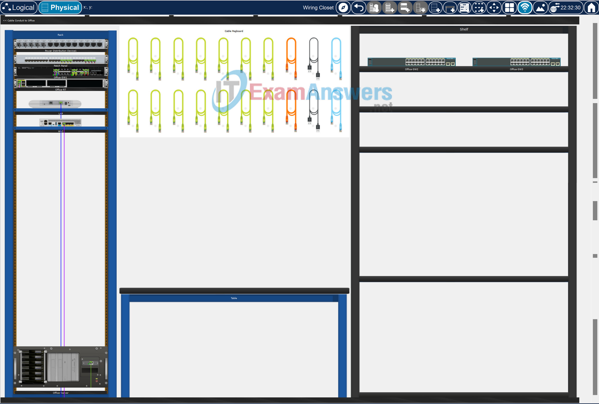
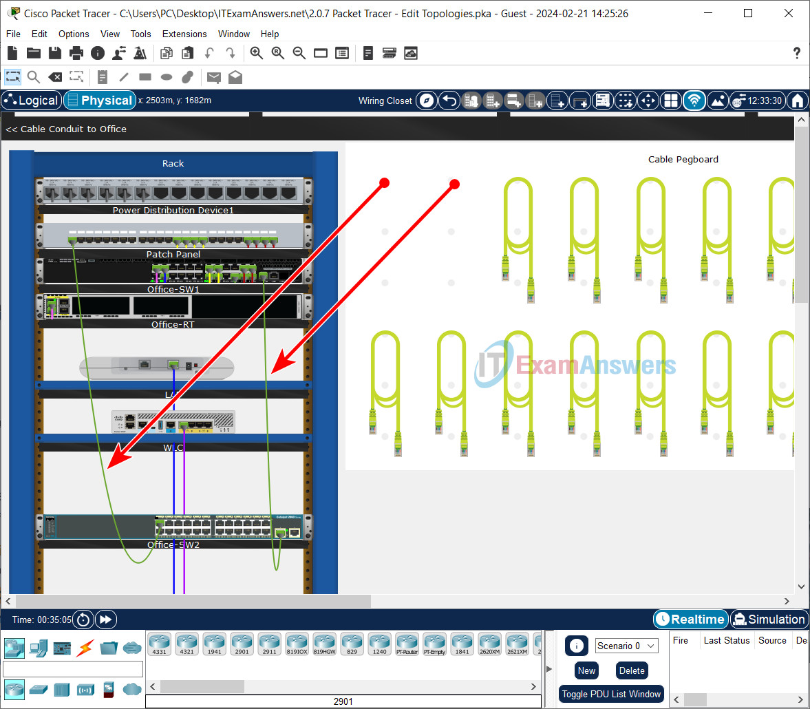
a. In the Wiring Closet, click and drag switch Office-SW2 from the Shelf on the right to the Rack on the left. It can be placed on any open space on the Rack.
b. Select a copper straight-through cable from the Cable Pegboard.
c. Connect the cable to switchport FastEthernet 0/1 on switch Office-SW2 and connect the other end to Jack 1 on the Patch Panel.
d. Select another copper straight-through cable from the Cable Pegboard.
e. Connect the cable to Switchport GigabitEthernet 0/1 on switch Office-SW2 and connect the other end to switchport GigabitEthernet1/1/1 on Office-SW1.
Part 2: Connect a PC to the Office Network
Step 1: Connect PC to wall mount.
a. Return to the Office topology using the Alt-Left Arrow key.
b. Add a straight-through cable from the Office-User to the copper wall mount.
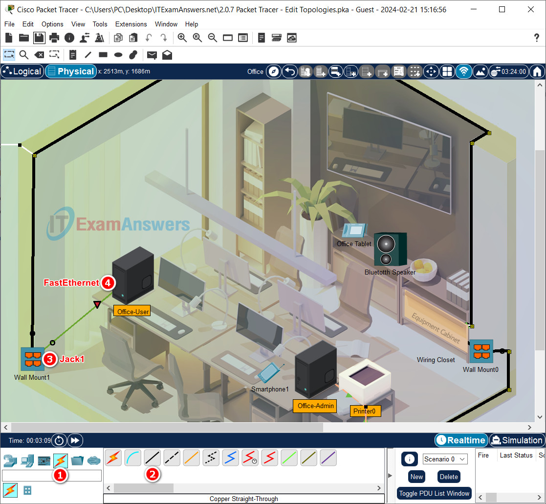
c. Click the Connections icon (i.e., orange lightning bolt) in the bottom left-hand corner.
d. Select a copper straight-through cable.
e. Connect the cable to the Copper Wall Mount1 and select Jack1. Connect the other end of the cable to FastEthernet0 on Office-User.
f. Select another copper straight-through cable
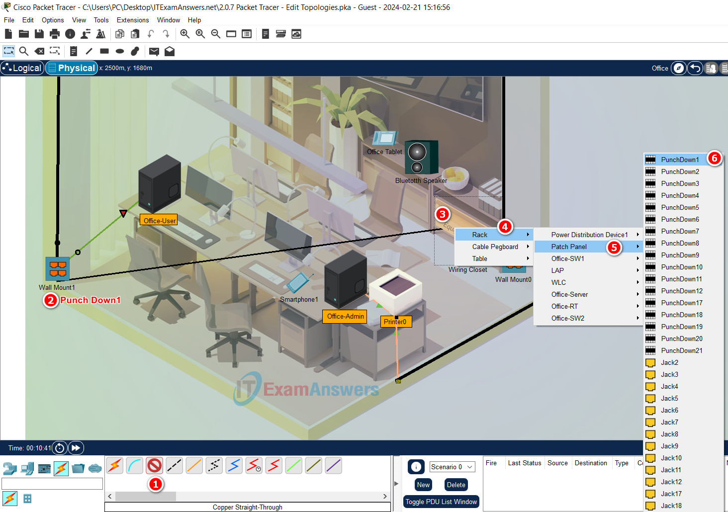
g. Click the Copper Wall Mount1 and select Punch Down1.
h. Connect the other end of the cable to PunchDown1 on the Patch Panel in the Equipment Cabinet. Click the Equipment Cabinet label in the lower right corner of the office.
i. Click Rack, then Patch Panel, then PunchDown1.
Step 2: Test network connectivity from PC-PT.
Enable DHCP on Office-User PC: Click the Office-User PC > Desktop tab > IP Configuration > Check DHCP
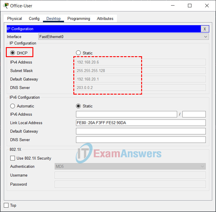
From Office-User, ping the Office-Admin PC at 192.168.20.5.
a. Select the Office-User and click the Desktop tab.
b. Click the Command Prompt.
c. In the Command Prompt, ping the Office-Admin PC. The pings should be successful.
C:\> ping 192.168.20.5
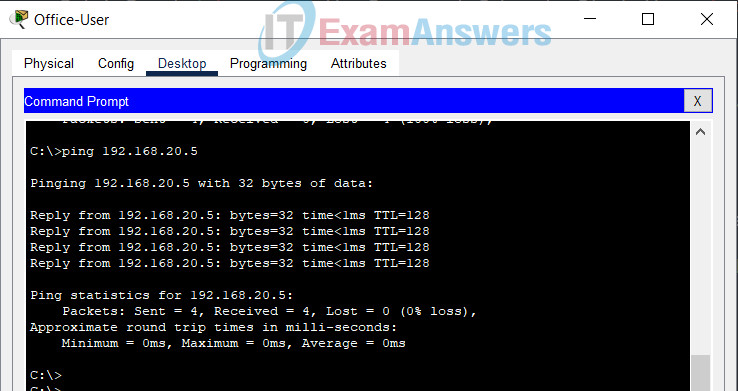
d. Exit the Command Prompt. Open a Web Browser and navigate to office.srv. It should be successful.
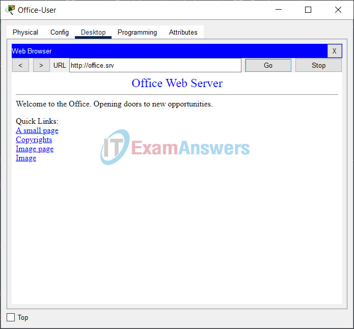
If it is not successful, verify that the cables are connected correctly.
Part 3: Work with Clusters
Step 1: View the city in logical mode.
a. While still in the Office, click Back Level.
b. Change the Packet Tracer workspace to Logical mode.
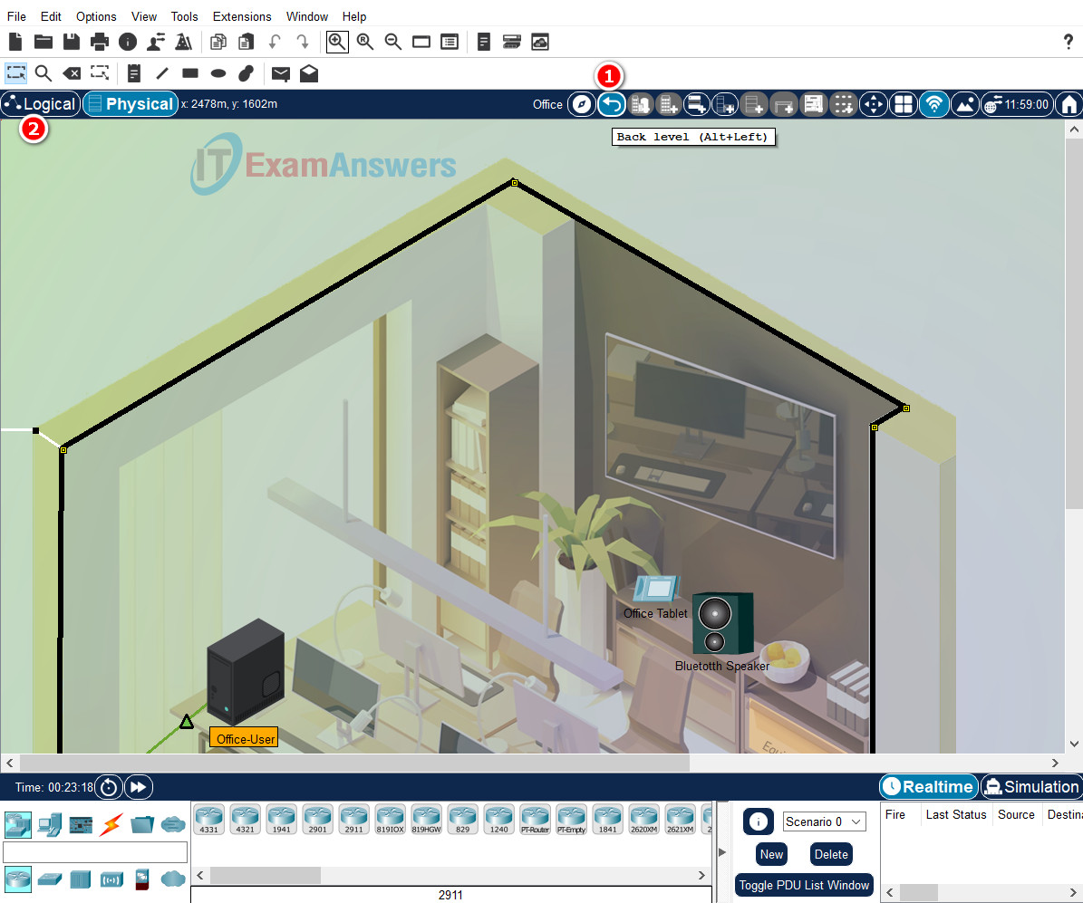
Step 2: Un-cluster and re-cluster the devices in an existing cluster.
a. Click anywhere in the workspace, hold the mouse button down and drag a rectangle around the Library cluster to select it.
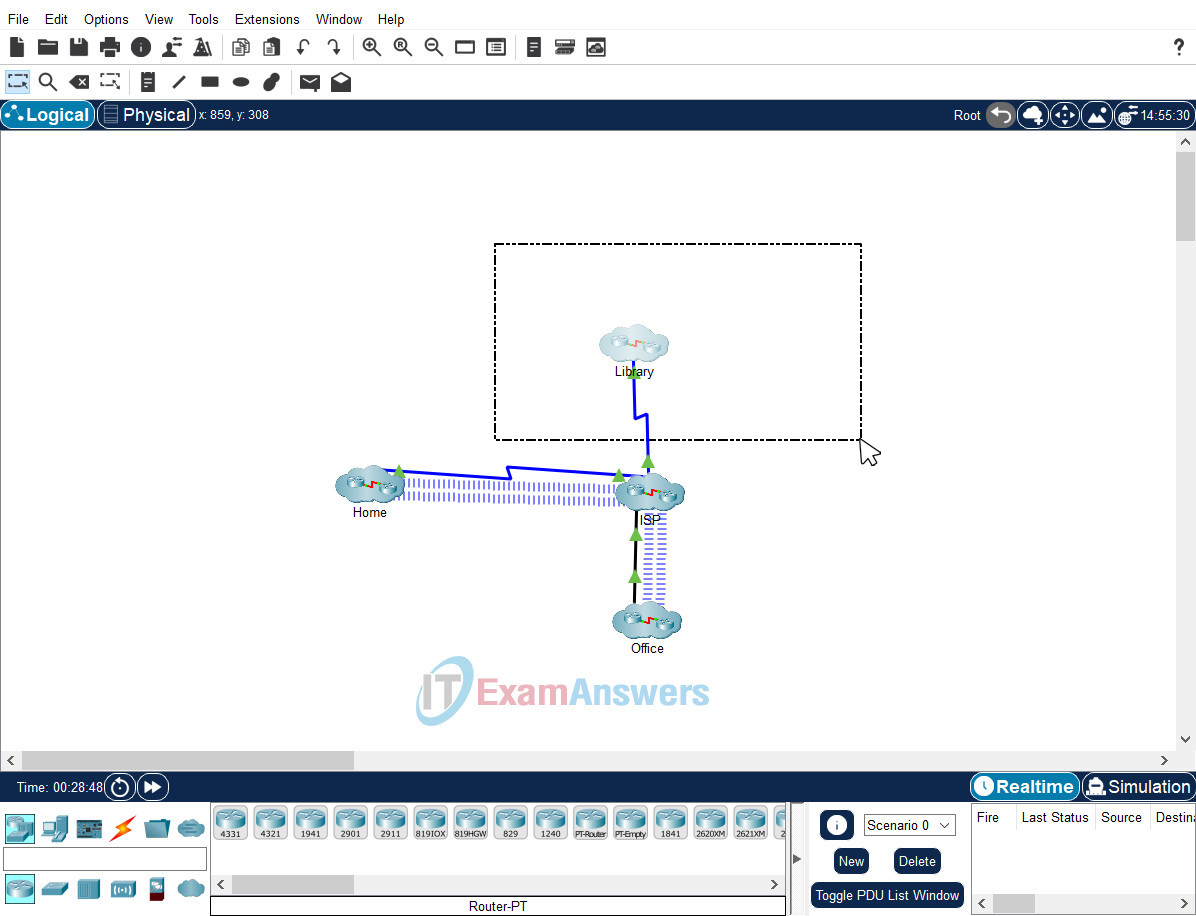
b. With the Library cluster selected, press delete on the keyboard.
c. You will be prompted to confirm the delete. Click Uncluster in the Confirm Delete dialog box.
Note: If the Library cluster is deleted, instead of unclustered, click undo (Ctrl + Z), or reset the activity. (Click File > Reset Activity or Alt + N)
d. All the devices in the Library should now be un-clustered on the workspace. Click Select or Esc to change the cursor from an X to a pointer.
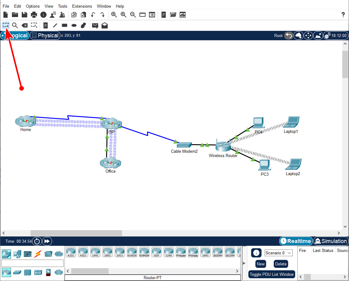
Step 3: Re-cluster the devices in the Library cluster.
a. Click anywhere in the workspace, hold the mouse button down and drag a rectangle around all the un-clustered library devices to select them.
b. With all the library devices selected, click the Create New Cluster (Shift + U) in the top-right corner of the workspace.
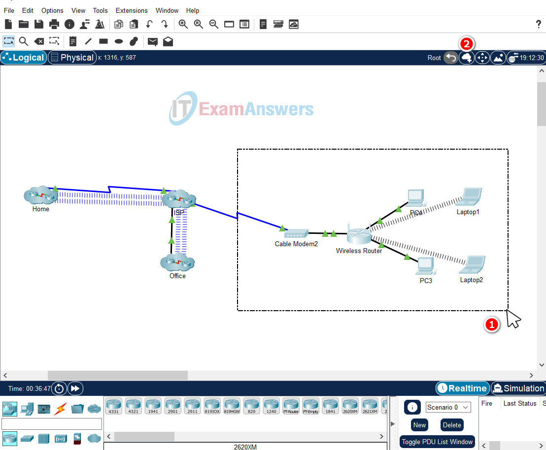
c. If you missed a device during the re-cluster process, click Move Object (Shift + M) and click the object to be moved. Select the desired location. In this example, it will be Cluster1 > Move to Cluster1.
d. When the devices are re-clustered, click the cluster name and change it back to Library.
Part 4: Add a Second Home Cluster to the Network
Step 1: Add devices to the workspace.
Add a PC, Home Gateway, and a Cable Modem to the workspace.
a. From the End Devices Selection Box, select PC from the End Devices and add it to the workspace.
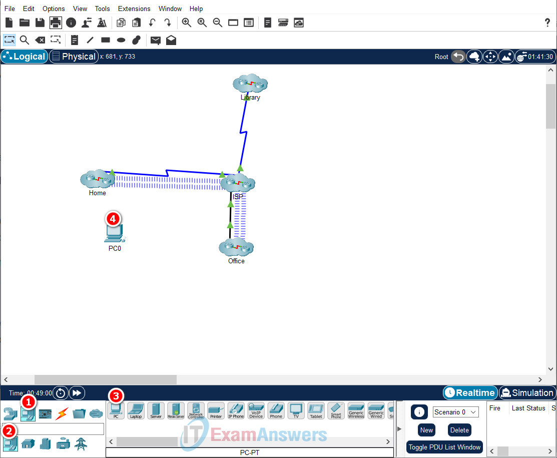
b. From the Network Devices Selection Box, place a Home Gateway from the Wireless Devices and cable modem from WAN Emulation Devices onto the workspace.
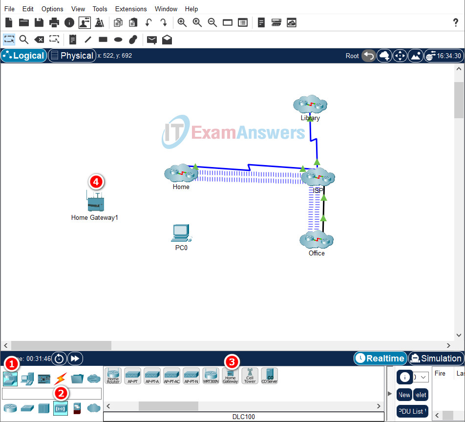
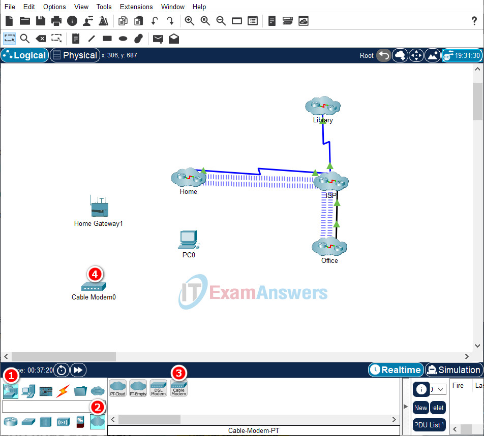
Step 2: Connect the devices in the Second Home cluster.
a. Select a copper straight-through cable and connect the FastEthernet0 port of PC0 to the Ethernet 1 port of the Home Gateway1.
b. Select another copper straight-through cable and connect the Internet port of the Home Gateway1 to Port 1 of the Cable Modem0.
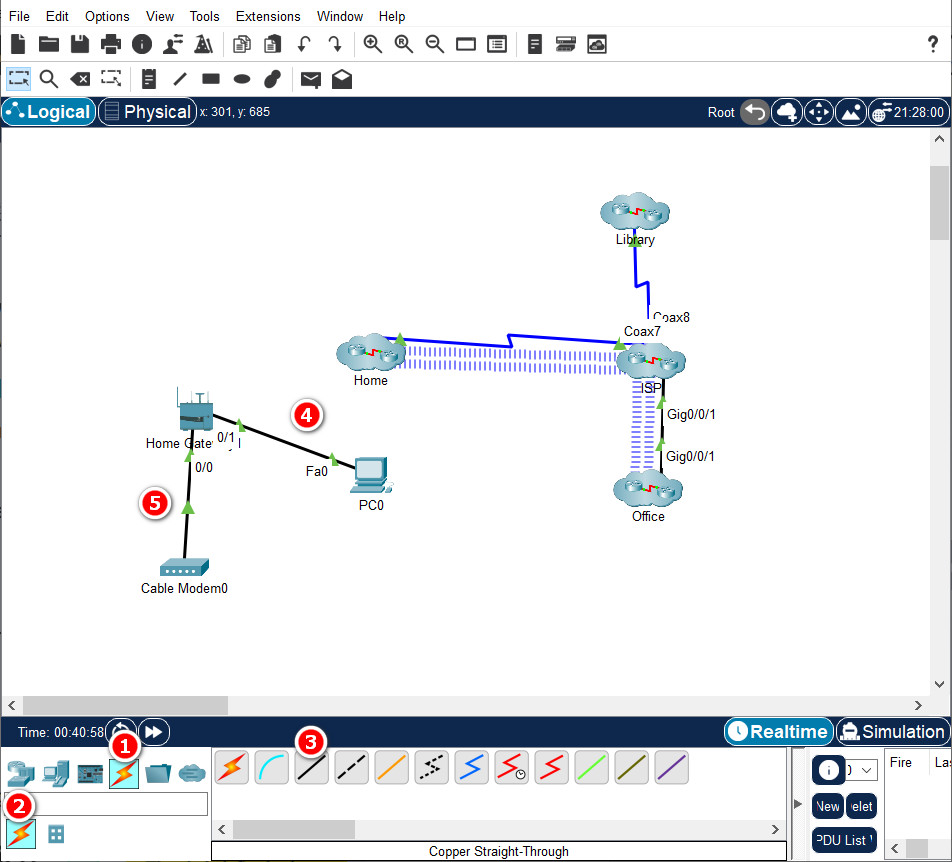
Step 3: Cluster the devices.
a. Click anywhere in the workspace, hold the mouse button down and drag a rectangle around all the un-clustered devices for the Second Home to select them.
b. With all the devices selected, click the Create New Cluster icon in the top right corner of the workspace.
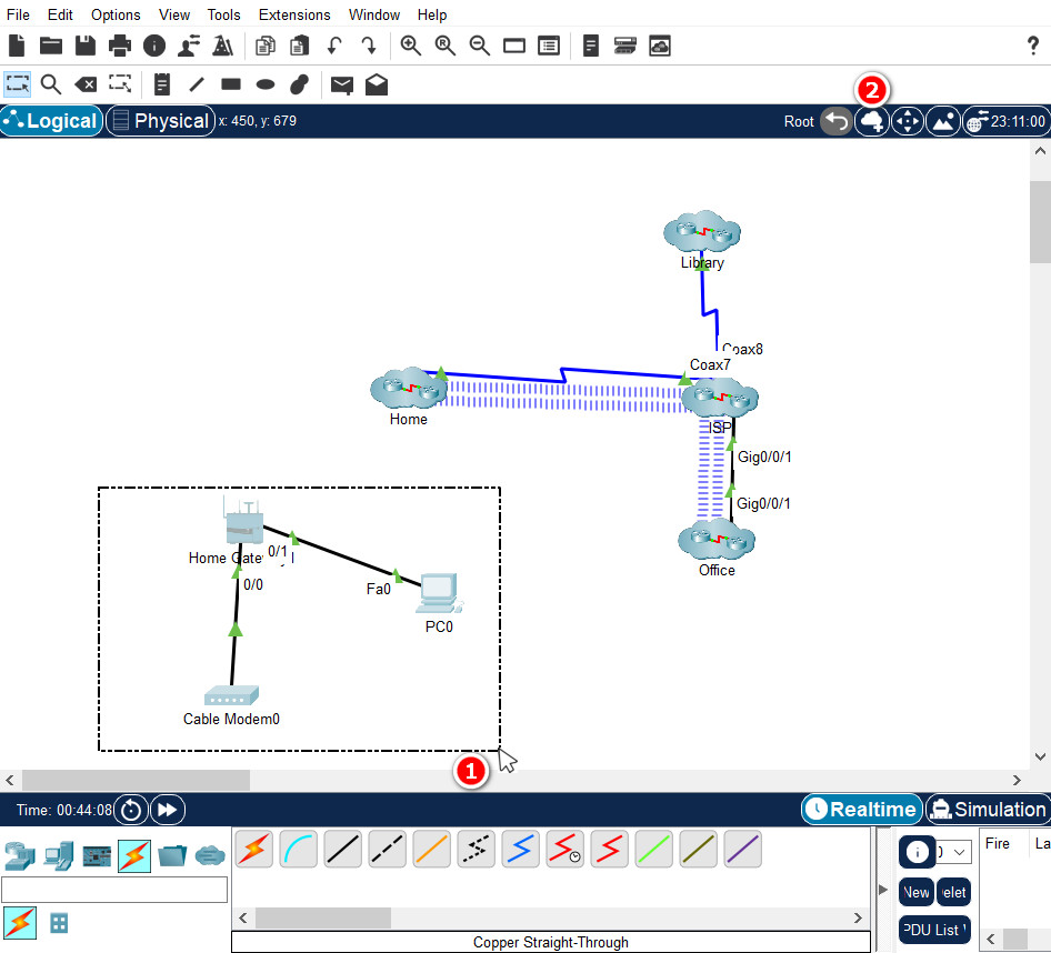
c. When the devices are clustered, click the cluster name and change it to Second Home.
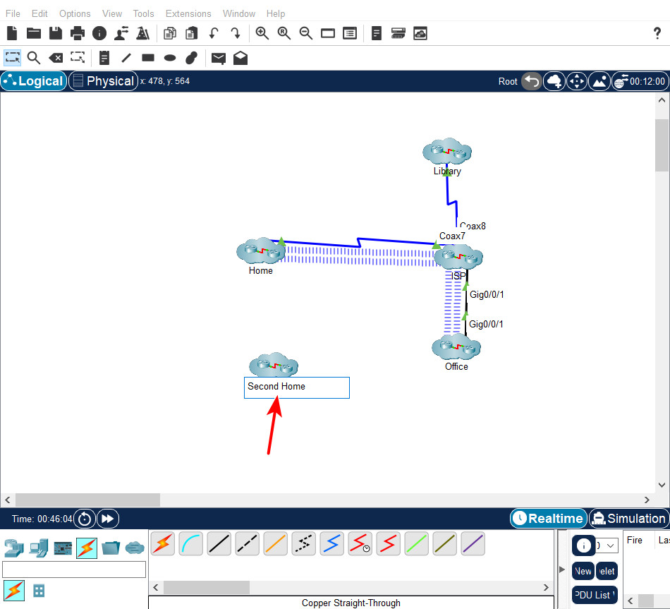
Step 4: Connect the Second Home to the ISP.
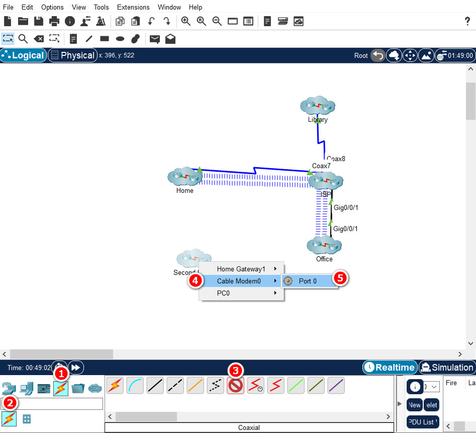
a. Select the blue Coaxial cable. Click the Second Home cluster.
b. In the device list for the Second Home, select the Cable Modem0 and connect the cable to Port 0 which is a coaxial port on the modem.
c. Click the ISP cluster and select the Cloud0 device and Coaxial9.
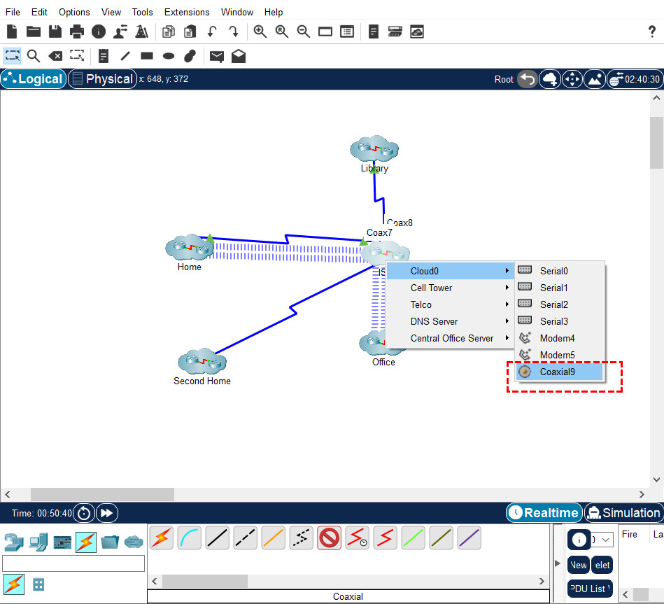
d. The Second Home cluster is now connected to the ISP.
Step 5: Use a Note to document the devices added to the Second Home cluster
a. Document which items were added to the second home cluster. Click the Place Note icon in the tool bar then click the workspace next to the Second Home cluster to add a note.
b. In the note, type the devices that were added to the Second Home cluster.
