2.7.3 Packet Tracer – Solving the Missing Route Answers
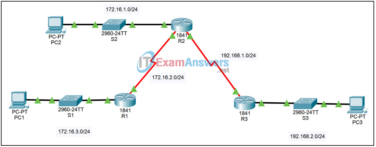
Topology

| Device | Interface | IP Address | Subnet Mask | Default Gateway |
|---|---|---|---|---|
| R1 | Fa0/0 | 172.16.3.1 | 255.255.255.0 | N/A |
| S0/0/0 | 172.16.2.1 | 255.255.255.0 | N/A | |
| R2 | Fa0/0 | 172.16.1.1 | 255.255.255.0 | N/A |
| S0/0/0 | 172.16.2.2 | 255.255.255.0 | N/A | |
| S0/0/1 | 192.168.1.2 | 255.255.255.0 | N/A | |
| R3 | Fa0/0 | 192.168.2.1 | 255.255.255.0 | N/A |
| S0/0/1 | 192.168.1.1 | 255.255.255.0 | N/A | |
| PC1 | NIC | 172.16.3.10 | 255.255.255.0 | 172.16.3.1 |
| PC2 | NIC | 172.16.1.10 | 255.255.255.0 | 172.16.1.1 |
| PC3 | NIC | 192.168.2.10 | 255.255.255.0 | 192.168.2.1 |
Introduction:
In this activity, we will examine the problem of a misconfigured static route. We will use Packet Tracer’s simulation mode to trace the packets through the misconfigured network. We will correct the network and view the proper operation.
Learning Objectives:
- Examine the network.
- View the configuration.
- Verify connectivity.
- View the problem in Simulation mode.
- Run the simulation.
- Examine the results.
- Correct the problem and verify.
- Replace the misconfigured static route.
- Verify connectivity.
- Rerun the simulation.
Task 1: Examine the network.
Step 1 – View the configuration.
On each of the three routers:
1. Login to the router using password cisco. Enter privileged exec mode using password class.
2. Enter the command show running-config to see how static routing is currently configured.
3. Enter the command show ip route to see the effect of the configuration.
Step 2 – Verify connectivity.
From the command line prompt on PC2, ping PC1 at 172.16.3.10. The ping times out.
Task 2: View the problem in Simulation mode.
Step 1 – Run the simulation.
1. Enter Simulation mode. The simulation is set to show only ICMP events. The PDU at PC2 is an ICMP echo request intended for PC1. To speed up the process, the PDU has been modified to have an initial TTL value of 15.
2. Run the simulation by clicking the Auto Capture / Play button.
3. Watch the animation as the packets bounce back and forth between router R2 and router R3 as events are added to the Event List.
4. When the simulation ends, click the View Previous Events button in the Buffer Full dialog box.
Step 2 – Examine the results.
1. Scroll to the top of the Event List. Click the colored box in the Info column for the first event. The PDU Information window opens.
2. Examine the Layer 3 information for both the In Layers and Out Layers on the OSI Model tab. Also, examine the Inbound PDU Details and Outbound PDU Details tabs noting the value in the TTL field.
3. View the information for the remaining events at the TTL field counts down, the packet is discarded, and a time exceeded message is sent to the source. Without this process the packet would loop forever.
Task 3: Correct the problem and verify.
Step 1 – Replace the misconfigured static route.
Return to Realtime mode. On router R2 enter global configuration mode and enter the following commands:
- R2(config)# no ip route 172.16.3.0 255.255.255.0 s0/0/1
- R2(config)# ip route 172.16.3.0 255.255.255.0 s0/0/0
Step 2 – Save the updated configuration.
On router R2, exit configuration mode by hitting Ctrl+z. Save the configuration by issuing the command copy run start.
Step 3 – Verify connectivity.
From the command line prompt on PC2, ping PC1 at 172.16.3.10. The ping should succeed, if not troubleshoot the static route.
Step 4 – Rerun the simulation.
Run the simulation as described in Task 2 to view the proper operation of the network.
