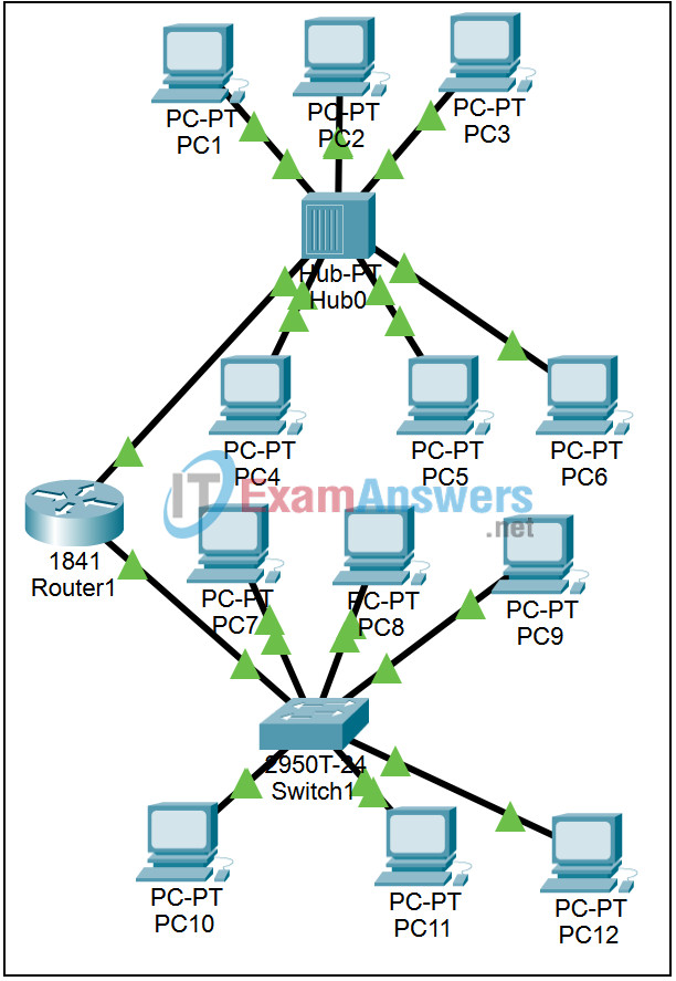
9.6.2 Packet Tracer – From Hubs to Switches Answers
Topology

Learning Objectives
- Observe the operation of a hub
- Observe the operation of a switch
- Observe the collision-free operation of a switch
Introduction:
A hub is a simple Layer 1 device that is used to connect devices. When a hub receives a frame on any port it sends the frame out all of the other ports. A switch operates at Layer 2 and learns the physical address of devices connected to each port. A switch stores this information in a table. If the switch receives a frame destined for a device with a physical address that is in its table, it only sends the frame out the port the device is on. This activity will compare the operation of a hub with the operation of a switch. If you experience a delay waiting for the switch link lights to turn from amber to green, toggling between Realtime and Simulation mode 3 or 4 times will speed up the process.
Task 1: Observe the operation of a hub.
Step 1. Enter Simulation mode.
Switch to Simulation mode.
Step 2. Set Event List Filters.
We want to capture only ARP and ICMP events. In the Event List Filters section, verify that only ARP and ICMP events will be displayed.
Step 3. Ping from PC1 to PC6.
Use the Add Simple PDU (the closed envelope) to send a single ping from PC1 to PC6. Click on PC1, the source, and then click on PC6, the destination. Two events appear in the Event List, an ICMP echo request and an ARP request to learn the MAC address of PC6. Click on the colored boxes in the Info column to examine these events.
Step 4. Step through the simulation.
Click the Capture / Forward button again and again, opening the packets for examination at each step in the process. Notice how the hub treats the broadcast ARP request, the unicast ARP reply, and the unicast ICMP echo request and echo reply.
Task 2: Observe the operation of a switch.
Step 1. Clear the simulation.
Clear the simulation by using the Delete button to delete Scenario 0.
Step 2. Ping from PC7 to PC12.
Use the Add Simple PDU (the closed envelope) to send a single ping from PC7 to PC12. Click on PC7, the source, and then click on PC12, the destination. Two events appear in the Event List, an ICMP echo request and an ARP request to learn the MAC address of PC12. Click on the colored boxes in the Info column to examine these events.
Step 3. Step through the simulation.
Click the Capture / Forward button again and again, opening the packets for examination at each step in the process. Notice how the switch treats the broadcast ARP request, the unicast APR reply, and the unicast ICMP echo request and echo reply.
Task 3: Observe the collision-free operation of a switch.
In Activity 9.4.2, we learned that collisions allow only one exchange to be sent between PCs at a time, in a LAN built with hubs. We will send three simultaneous requests through the switch.
Step 1. Reset the simulation.
Reset the simulation by clicking the Reset Simulation button.
Step 2. Simultaneously ping between multiple PCs.
Use the Add Simple PDU (the closed envelope) to add a single ping from PC8 to PC11. Click on PC8, the source, and then click on PC11, the destination. Do the same between PC9 and PC10. Four more events appear in the Event List, two ICMP echo requests and two ARP requests to learn the MAC address of PC11 and PC 10. Click on the colored boxes in the Info column to examine these events.
Step 3. Step through the simulation.
Click the Capture / Forward button again and again, opening the packets for examination at each step in the process. Notice how the switch handles the volume of traffic without collisions.
