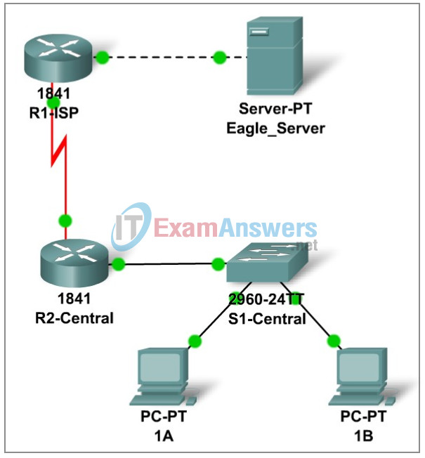
9.9.1 Packet Tracer – Skills Integration Challenge-Switched Ethernet Answers
Topology Diagram:

Addressing Table
| Device | Interface | IP Address | Subnet Mask | Default Gateway |
|---|---|---|---|---|
| R1-ISP | Fa0/0 | 192.168.111.134 | 255.255.255.248 | N/A |
| S0/0/0 | 192.168.111.138 | 255.255.255.252 | ||
| R2-Central | Fa0/0 | 192.168.111.126 | 255.255.255.128 | N/A |
| S0/0/0 | 192.168.111.137 | 255.255.255.252 | ||
| PC 1A | NIC | 192.168.111.1 | 255.255.255.128 | 192.168.111.126 |
| PC 1B | NIC | 192.168.111.2 | 255.255.255.128 | 192.168.111.126 |
| Eagle Server | NIC | 192.168.111.133 | 255.255.255.248 | 192.168.111.134 |
Learning Objectives:
- IP subnet planning.
- Repair Ethernet-related network issues.
- Test the network.
Background:
You have been asked to repair some problems in the network model related to the Ethernet LAN connected to R2-Central.
Task 1: IP Subnet planning
You have been given an IP address block of 192.168.111.0 /24. You must provide for the three existing networks.
Subnet Assignments Are:
- 1st subnet, existing student LAN, up to 100 hosts; (Fa0/0 on R2-Central)
- 2nd subnet, existing ISP LAN, up to 5 hosts; (already configured)
- 3rd subnet, existing WAN, point-to-point link; (already configured)
Interface IP addresses:
- The server, R1-ISP, and R2-Central’s serial interface have already been configured.
- For R2-Central’s Fa0/0 interface, use the highest usable address on the existing student LAN subnet.
- For hosts 1A and 1B, use the first 2 IP addresses (two lowest usable addresses) on the existing student LAN subnet.
- For Hosts 1A and 1B, the DNS server is 192.168.111.133 /29.
- The next hop router (to which the default route should point), R1-ISP, has an IP address of 192.168.111.138 /30.
Task 2: Repair problems with the Ethernet switched LAN.
- PC 1B has a wireless card and cannot be connected to the switch; add the Fast Ethernet Interface card PT-HOST-NM-1CFE to PC 1B.
- Connect this newly installed Fast Ethernet NIC to the Fa0/2 interface on the switch.
- Connect PC 1A to the Fa0/1 interface on the switch.
- Connect the Fa0/24 interface on the switch to the R2-Central Fa0/0 interface.
Apparently the Ethernet speed and duplex settings for the R2-Central Fa0/0 interface, the S1-Central switch interfaces (Fa0/1, Fa0/2, and Fa0/24), and the PC 1A interfaces are incorrect. Set all Ethernet interfaces to auto negotiate speed and duplex (which will achieve Full Duplex, 100 Mbps operation, if both ends of the link can support it). For all devices, make sure the power is on to the device and to the interfaces (make sure the Ethernet interfaces are not shut down). Add IP addresses to the router Fa0/0 interface and to the two PCs. Assign the highest usable subnet address to the gateway and two lowest usable addresses to the PCs. The static route on the R2-Central should be a default static route which points via R1-ISP’s serial interface IP address. These procedures were explained in the Chapter 5 and 6 Skills Integration Challenges.
Task 3: Test the Network.
Use ping, trace, web traffic, and the Inspect tool to trace packet flow in simulation mode, with HTTP, DNS, TCP, UDP, ICMP, and ARP viewable, to test your understanding of how the network is operating.
Reflection:
The two Layer 2 (and Layer 1 technologies) in this model are a serial connection (between the routers) and the Ethernet LANs (for the ISP server and with S1-Central switch). Compare and contrast the serial connection with Ethernet. In a future course you will learn much more about switched Ethernet technologies.
