CCNA Security 2.0 Study Material – Chapter 2: Securing Network Devices
2.0 Introduction
2.0.1 Welcome
2.0.1.1 Securing Network Devices
Configure a Network Operating System
Every computer requires an operating system to function, including computer-based network devices such as switches, routers, access points, and firewalls. These network devices use an operating system called a network operating system.
A network operating system enables device hardware to function and provides an interface for users to interact. In the CCNA course of study, students learn to configure both devices that connect to the network (end devices such as PCs) and devices that connect networks together (intermediary devices like routers and switches). Learning to configure the Cisco Internetwork Operating System (Cisco IOS) on Cisco routers and switches is a large part of the Cisco CCNA program of study.
The Cisco Internetwork Operating System (IOS) is a generic term for the collection of network operating systems used by Cisco networking devices. Cisco IOS is used for most Cisco devices, regardless of the type or size.

2.1 Securing Device Access
2.1.1 Securing the Edge Router
2.1.1.1 Securing the Network Infrastructure
Operating Systems
All end devices and network devices require an operating system (OS). As shown in Figure 1, the portion of the OS that interacts directly with computer hardware is known as the kernel. The portion that interfaces with applications and the user is known as the shell. The user can interact with the shell using a command-line interface (CLI) or a graphical user interface (GUI).
When using a CLI as shown in Figure 2, the user interacts directly with the system in a text-based environment by entering commands on the keyboard at a command prompt. The system executes the command, often providing textual output. The CLI requires very little overhead to operate. However, it does require that the user have knowledge of the underlying structure that controls the system.
A GUI interface such as Windows, OS X, Apple iOS, or Android allows the user to interact with the system using an environment of graphical icons, menus, and windows. The GUI example in Figure 3 is more user-friendly and requires less knowledge of the underlying command structure that controls the system. For this reason, many individuals rely on GUI environments.
However, GUIs may not always be able to provide all of the features available at the CLI. GUIs can also fail, crash, or simply not operate as specified. For these reasons, network devices are typically accessed through a CLI. The CLI is less resource intensive and very stable when compared to a GUI.
The network operating system used on Cisco devices is called the Cisco Internetwork Operating System (IOS). Cisco IOS is used for most Cisco devices regardless of the type or size of the device.
Note: The operating system on home routers is usually called firmware. The most common method for configuring a home router is by using a web browser-based GUI.
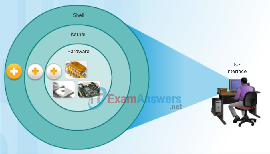
Operating System
- Shell: The user interface that allows users to request specific tasks from the computer. These requests can be made either through the CLI or GUI interfaces.
- Kernel: Communicates between the hardware and software of a computer and manages how hardware resources are used to meet software requirements.
- Hardware: The physical part of a computer including underlying electronics.
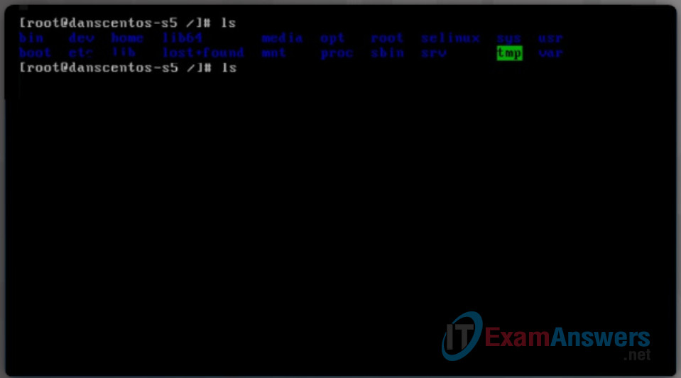
Command-Line Interface
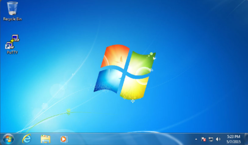
Command-Line Interface
2.1.1.2 Edge Router Security Approaches
Purpose of OS
Network operating systems are similar to a PC operating system. Through a GUI, a PC operating system enables a user to:
- Use a mouse to make selections and run programs
- Enter text and text-based commands
- View output on a monitor
A CLI-based network operating system like the Cisco IOS on a switch or router enables a network technician to:
- Use a keyboard to run CLI-based network programs
- Use a keyboard to enter text and text-based commands
- View output on a monitor
Cisco networking devices run particular versions of the Cisco IOS. The IOS version is dependent on the type of device being used and the required features. While all devices come with a default IOS and feature set, it is possible to upgrade the IOS version or feature set to obtain additional capabilities.
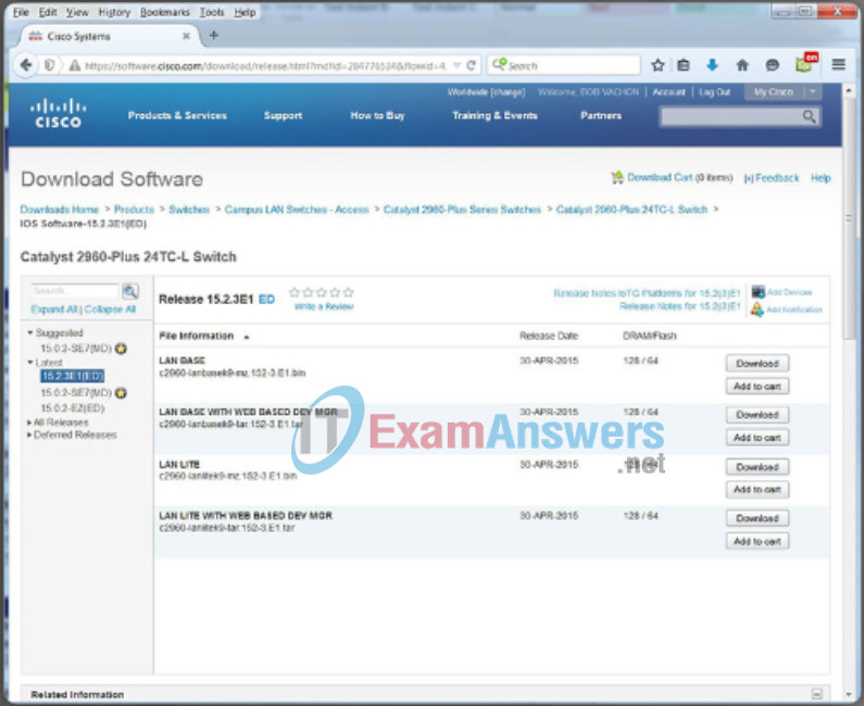
In this course, you will focus primarily on Cisco IOS Release 15.x. The figure displays a list of IOS software releases for a Cisco Catalyst 2960 Switch.
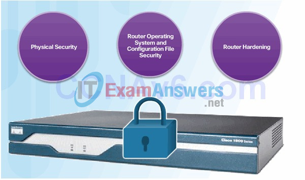
2.1.1.3 Three Areas of Router Security
2.1.1.4 Secure Administrative Access
Tasks:
- Restrict device accessibility
- Log and account for all access
- Authenticate access
- Authorize actions
- Present legal notification
- Ensure the confidentiality of data
2.1.1.5 Secure Local and Remote Access
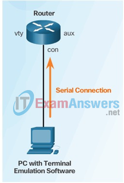
Local Access

Remote Access Using Telnet

Remote Access Using Modem and Aux Port
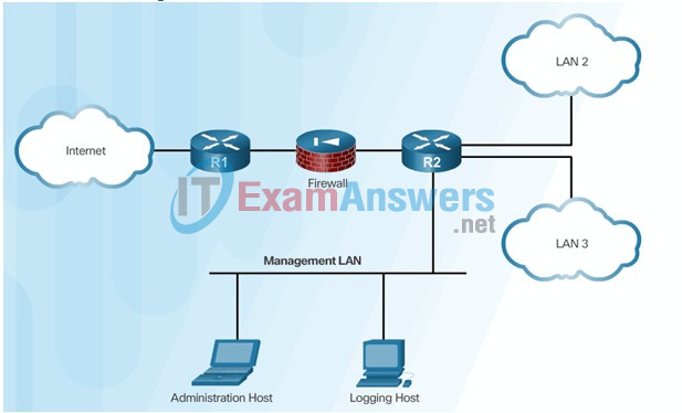
Dedicated Management Network
2.1.2 Configuring Secure Administrative Access
2.1.2.1 Strong Passwords
Access Methods
A Cisco IOS switch can be implemented with no configuration and still switch data between connected devices. By connecting two PCs to a switch, those PCs will instantly have connectivity with one another.
Even though a Cisco switch will function immediately, configuring initial settings are a recommended best practice. There are several ways to access the CLI environment and configure the device. The most common methods are:
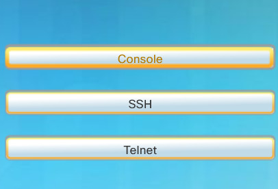
Console – This is a physical management port that provides out-of-band access to a Cisco device. Out-of-band access refers to access via a dedicated management channel that is used for device maintenance purposes only.
Secure Shell (SSH) – SSH is a method for remotely establishing a secure CLI connection through a virtual interface, over a network. Unlike a console connection, SSH connections require active networking services on the device including an active interface configured with an address.
Telnet – Telnet is an insecure method of remotely establishing a CLI session through a virtual interface, over a network. Unlike SSH, Telnet does not provide a securely encrypted connection. User authentication, passwords, and commands are sent over the network in plaintext.
Click the options in the figure to view additional information.
Note: Some devices, such as routers, may also support a legacy auxiliary port that was used to establish a CLI session remotely using a modem. Similar to a console connection, the AUX port is out-of-band and does not require networking services to be configured or available.
- Console: The advantage of using a console port is that the device is accessible even if no networking services have been configured, such as when performing an initial configuration of the networking device. When performing an initial configuration, a computer running terminal emulation software is connected to the console port of the device using a special cable. Configuration commands for setting up the switch or router can be entered on the connected computer.
- SSH: SSH is the recommended method for remote management because it provides a secure connection. SSH provides encrypted password authentication and transport of session data. This keeps the user ID, password, and the details of the management session private. Most versions of Cisco IOS include an SSH server and an SSH client that can be used to establish SSH sessions with other devices.
- Telnet: Best practice dictates to use SSH instead of Telnet for remote management CLI connections. Cisco IOS includes a Telnet server and a Telnet client that can be used to establish Telnet sessions with other devices.
2.1.2.2 Increasing Access Security
Terminal Emulation Programs
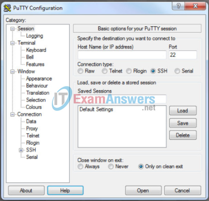
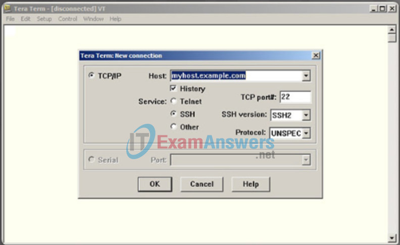
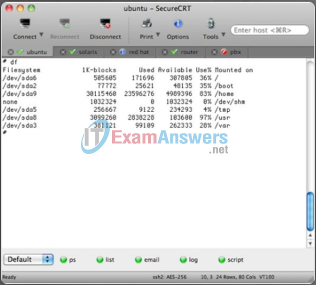
There are a number of excellent terminal emulation programs available for connecting to a networking device either by a serial connection over a console port or by a SSH/Telnet connection. Some of these include:
- PuTTY (Figure 1)
- Tera Term (Figure 2)
- SecureCRT (Figure 3)
- OS X Terminal
These programs allow you to enhance your productivity by adjusting window sizes, changing font sizes, and changing color schemes.
PuTTY
Tera Term
SecureCRT
2.1.2.3 Secret Password Algorithms
Guidelines:
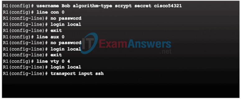
- Configure all secret passwords using type 8 or type 9 passwords
- Use the enable algorithm-type command syntax to enter an unencrypted password

Use the username name algorithm-type command to specify type 9 encryption

2.1.2.4 Securing Line Access
2.1.3 Configuring Enhanced Security for Virtual Logins
2.1.3.1 Enhancing the Login Process
Cisco IOS Modes of Operation
To initially configure a Cisco device, a console connection must be established. Once consoled in, the network technician will have to navigate through various command modes of the IOS CLI. The Cisco IOS modes use a hierarchical structure and are quite similar for both switches and routers.
2.1.3.2 Configuring Login Enhancement Features
Primary Command Modes
As a security feature, the Cisco IOS software separates management access into the following two command modes:
- User EXEC Mode – This mode has limited capabilities but is useful for basic operations. It allows only a limited number of basic monitoring commands but does not allow the execution of any commands that might change the configuration of the device. The user EXEC mode is identified by the CLI prompt that ends with the > symbol.
- Privileged EXEC Mode – To execute configuration commands, a network administrator must access privileged EXEC mode. Higher configuration modes, like global configuration mode, can only be reached from privileged EXEC mode. The privileged EXEC mode can be identified by the prompt ending with the # symbol.
The table in the figure summarizes the two modes and displays the default CLI prompts of a Cisco switch and router.
| Command Mode | Description | Default Device Prompt |
|---|---|---|
| User Exec Mode | Mode allows access to only a limited number of basic monitoring commands. It is often referred to as “view-only” mode. |
Switch> Router> |
| Privileged EXEC Mode | Mode allows access to all commands and features. The user can use any monitoring commands and execute configuration and management commands. |
Switch# Router# |
2.1.3.3 Enable Login Enhancements
Configuration Command Modes
To configure the device, the user must enter Global Configuration Mode, which is commonly called global config mode.
From global config mode, CLI configuration changes are made that affect the operation of the device as a whole. Global configuration mode is identified by a prompt that ends with (config)# after the device name, such as Switch(config)#.
Global configuration mode is accessed before other specific configuration modes. From global config mode, the user can enter different sub-configuration modes. Each of these modes allows the configuration of a particular part or function of the IOS device. Two common sub-configuration modes include:
- Line Configuration Mode – Used to configure console, SSH, Telnet, or AUX access.
- Interface Configuration Mode – Used to configure a switch port or router network interface.
When using the CLI, the mode is identified by the command-line prompt that is unique to that mode. By default, every prompt begins with the device name. Following the name, the remainder of the prompt indicates the mode. For example, the default prompt for line configuration mode is Switch(config-line)# and the default prompt for interface configuration mode is Switch(config-if)#.
2.1.3.4 Logging Failed Attempts
Navigate Between IOS Modes
Various commands are used to move in and out of command prompts. To move from user EXEC mode to privileged EXEC mode, use the enable command. Use the disable privileged EXEC mode command to return to user EXEC mode.
Note: Privileged EXEC mode is sometimes called enable mode.
To move in and out of global configuration mode, use the configure terminal privileged EXEC mode command. To return to the privileged EXEC mode, enter the exit global config mode command.
There are many different sub-configuration modes. For example, to enter line sub-configuration mode, you use the line command followed by the management line type and number you wish to access. To exit a sub-configuration mode and return to global configuration mode, use the exit command. Notice the changes in the command prompt.
Switch(config)# line console 0
Switch(config-line)#
To move from any sub-configuration mode of the global configuration mode to the mode one step above it in the hierarchy of modes, enter the exit command.
Switch(config-line)# exit

Switch(config)#
To move from any sub-configuration mode to the privileged EXEC mode, enter the end command or enter the key combination Ctrl+Z.
Switch(config-line)# end
Switch#
You can also move directly from one sub-configuration mode to another. Notice how after the network device name, the command prompt changes from (config-line)# to (config-if)#.
Switch(config-line)# interface FastEthernet 0/1
Switch(config-if)#
2.1.4 Configuring SSH
2.1.4.1 Steps for Configuring SSH
Basic IOS Command Structure
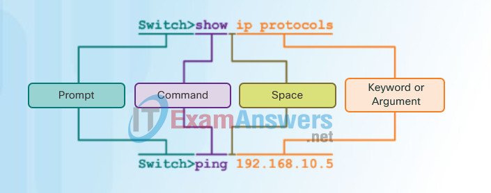
A Cisco IOS device supports many commands. Each IOS command has a specific format or syntax and can only be executed in the appropriate mode. The general syntax for a command is the command followed by any appropriate keywords and arguments.
- Keyword – a specific parameter defined in the operating system (in the figure, ip protocols)
- Argument – not predefined; a value or variable defined by the user (in the figure, 192.168.10.5)
After entering each complete command, including any keywords and arguments, press the Enter key to submit the command to the command interpreter.
2.1.4.2 Modifying the SSH Configuration
IOS Command Syntax
A command might require one or more arguments. To determine the keywords and arguments required for a command, refer to the command syntax. The syntax provides the pattern or format that must be used when entering a command.
As identified in the table in the figure, boldface text indicates commands and keywords that are entered as shown. Italic text indicates an argument for which the user provides the value.
For instance, the syntax for using the description command is description string. The argument is a string value provided by the user. The description command is typically used to identify the purpose of an interface. For example, entering the command, description Connects to the main headquarter office switch, describes where the other device is at the end of the connection.
The following examples demonstrate conventions used to document and use IOS commands.
- ping ip-address – The command is ping and the user-defined argument is the ip-address of the destination device. For example, ping 10.10.10.5.
- traceroute ip-address – The command is traceroute and the user-defined argument is the ip-address of the destination device. For example, traceroute 192.168.254.254.
The Cisco IOS Command Reference is the ultimate source of information for a particular IOS command.
When describing the use of commands, we generally use these conventions.
| Convention | Description |
|---|---|
| boldface | Boldface text indicates commands and keywords that you enter literally as shown. |
| italics | Italic text indicates arguments for which you supply values. |
| [x] | Square brackets indicate an optional element (keyword or argument). |
| {x} | Braces indicate a required element (keyword or argument). |
| [x {y | z}] | Braces and vertical lines within square brackets indicate a required choice within an optional element. |
2.1.4.3 Connecting to an SSH-Enabled Router
IOS Help Features
The IOS has two forms of help available:
- Context-Sensitive Help
- Command Syntax Check
Context-sensitive help enables you to quickly find which commands are available in each command mode, which commands start with specific characters or group of characters, and which arguments and keywords are available to particular commands. To access context-sensitive help, simply enter a question mark, ?, at the CLI.
Command syntax check verifies that a valid command was entered by the user. When a command is entered, the command line interpreter evaluates the command from left to right. If the interpreter understands the command, the requested action is executed, and the CLI returns to the appropriate prompt. However, if the interpreter cannot understand the command being entered, it will provide feedback describing what is wrong with the command.
2.2 Assigning Administrative Roles
2.2.1 Configuring Privilege Levels
2.2.1.1 Limiting Command Availability
Device Names
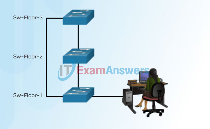
When configuring a networking device, one of the first steps is configuring a unique device name or hostname. Hostnames that appear in CLI prompts can be used in various authentication processes between devices, and should be used on topology diagrams.
If the device name is not explicitly configured, a factory assigned default name is used by the Cisco IOS. The default name for a Cisco IOS switch is “Switch.” If all network devices were left with their default names, it would be difficult to identify a specific device. For instance, when accessing a remote device using SSH, it is important to have confirmation that you are connected to the proper device.
By choosing names wisely, it is easier to remember, document, and identify network devices. Guidelines for hostname configuration are listed in Figure 1.
The hostnames used in the device IOS preserve capitalization and lowercase characters. Therefore, it allows you to capitalize a name as you ordinarily would. This contrasts with most Internet naming schemes, where uppercase and lowercase characters are treated identically.
For example, in Figure 2, three switches, spanning three different floors, are interconnected together in a network. The naming convention used took into consideration the location and the purpose of each device. Network documentation should explain how these names were chosen so additional devices can be named accordingly.
Guidelines to Choosing a Hostname
- Hostnames Should:
- Start with a letter
- Contain no spaces
- End with a letter or digit
- Use only letters, digits, and dashes
- Be less than 64 characters in length
Configuring Device Names
2.2.1.2 Configuring and Assigning Privilege Levels
Configure Hostnames
Once the naming convention has been identified, the next step is to apply the names to the devices using the CLI.
As shown in Figure 1, from the privileged EXEC mode, access the global configuration mode by entering the configure terminal command. Notice the change in the command prompt.
From global configuration mode, enter the command hostname followed by the name of the switch and press Enter. Notice the change in the command prompt name.
Note: To remove the configured hostname and return the switch to the default prompt, use the no hostname global config command.
Always make sure the documentation is updated each time a device is added or modified. Identify devices in the documentation by their location, purpose, and address.
Use the Syntax Checker in Figure 2 to practice entering a hostname on a switch.
Configure a Hostname
Switch# configure terminal
Switch(config)# hostname SW-Floor-1
Sw-Floor-1(config)#
Configure the Switch Hostname
Enter the configuration mode and configure the switch hostname to be ‘Sw-Floor-1’.
Switch# configure terminal
Switch(config)# hostname Sw-Floor-1
Sw-Floor-1(config)#
You have successfully configured the switch hostname.
2.2.1.3 Limitations of Privilege Levels
- No access control to specific interfaces, ports, logical interfaces, and slots on a router
- Commands available at lower privilege levels are always executable at higher privilege levels
- Commands specifically set at higher privilege levels are not available for lower privilege users
- Assigning a command with multiple keywords allows access to all commands that use those
2.2.2 Configuring Role-Based CLI
2.2.2.1 Role-Based CLI Access
Secure Device Access
The use of weak or easily guessed passwords continues to be a security issue in many facets of the business world. Network devices, including home wireless routers, should always have passwords configured to limit administrative access.
Cisco IOS can be configured to use hierarchical mode passwords to allow different access privileges to a network device.
All networking devices should limit access as listed in Figure 1.
Use strong passwords that are not easily guessed. Consider the key points listed in Figure 2.
Note: Most of the labs in this course use simple passwords such as cisco or class. These passwords are considered weak and easily guessable and should be avoided in production environments. We only use these passwords for convenience in a classroom setting or to illustrate configuration examples.
Limiting Device Access
Securing Administrative Access
- Secure privileged EXEC access with a password
- Secure user EXEC access with a password
- Secure remote Telnet access with a password
Other tasks
- Encrypt all passwords
- Provide legal notification
Password Choosing Guidelines
When Choosing Passwords
- Use passwords that are more than 8 characters in length.
- Use a combination of upper and lowercase letters, numbers, special characters, and/or numeric sequences.
- Avoid using the same password for all devices.
- Don’t use common words because these are easily guessed.
2.2.2.2 Role-Based Views
Configure Passwords
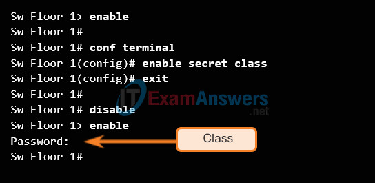
The most important password to configure is access to the privileged EXEC mode, as shown in Figure 1. To secure privileged EXEC access, use the enable secret password global config command.
To secure the user EXEC access, the console port must be configured, as shown in Figure 2. Enter line console configuration mode using the line console 0 global configuration command. The zero is used to represent the first (and in most cases the only) console interface. Next, specify the user EXEC mode password using the password password command. Finally, enable user EXEC access using the login command. Console access will now require a password before gaining access to the user EXEC mode.
Virtual terminal (VTY) lines enable remote access to the device. To secure VTY lines used for SSH and Telnet, enter line VTY mode using the line vty 0 15 global config command, as shown in Figure 3. Many Cisco switches support up to 16 VTY lines that are numbered 0 to 15. Next, specify the VTY password using the password password command. Lastly, enable VTY access using the login command.
Privileged EXEC Password Example
User EXEC Password Example
Sw-Floor-1(config)# line console 0
Sw-Floor-1(config-line)# password cisco
Sw-Floor-1(config-line)# login
Sw-Floor-1(config-line)# exit
Sw-Floor-1(config)#
VTY Line Password Example
Sw-Floor-1(config)# line vty 0 15
Sw-Floor-1(config-line)# password cisco
Sw-Floor-1(config-line)# login
Sw-Floor-1(config-line)#
2.2.2.3 Configuring Role-Based Views
Encrypt Passwords
The startup-config and running-config files display most passwords in plaintext. This is a security threat since anyone can see the passwords used if they have access to these files.
To encrypt passwords, use the service password-encryption global config command. The command applies weak encryption to all unencrypted passwords. This encryption applies only to passwords in the configuration file, not to passwords as they are sent over the network. The purpose of this command is to keep unauthorized individuals from viewing passwords in the configuration file.
Use the Syntax Checker in the figure to practice encrypting passwords.
Enter the command to encrypt the plaintext passwords.
Switch(config)# service password-encryption
Exit global configuration mode and view the running configuration.
Switch(config)# exit
Switch# show running-config
!
<output omitted>
!
line con 0
password 7 094F471A1A0A
login
!
line vty 0 4
password 7 03095A0F034F38435B49150A1819
login
!
!
end

Switch#
You successfully encrypted the plaintext passwords.
2.2.2.4 Configuring Role-Based CLI Superviews
Banner Messages
Although requiring passwords is one way to keep unauthorized personnel out of a network, it is vital to provide a method for declaring that only authorized personnel should attempt to gain entry into the device. To do this, add a banner to the device output. Banners can be an important part of the legal process in the event that someone is prosecuted for breaking into a device. Some legal systems do not allow prosecution, or even the monitoring of users, unless a notification is visible.
To create a banner message of the day on a network device, use the banner motd # the message of the day # global config command. The “#” in the command syntax is called the delimiting character. It is entered before and after the message. The delimiting character can be any character as long as it does not occur in the message. For this reason, symbols such as the “#” are often used. After the command is executed, the banner will be displayed on all subsequent attempts to access the device until the banner is removed.
Because banners can be seen by anyone who attempts to log in, the message must be worded very carefully. The exact content or wording of a banner depends on the local laws and corporate policies. The banner should state that only authorized personnel are allowed to access the device. Any wording that implies a login is “welcome” or “invited” is inappropriate. Further, the banner can include scheduled system shutdowns and other information that affects all network users.
2.2.2.5 Verify Role-Based CLI Views
Syntax Checker – Limiting Access to a Switch
Use the Syntax Checker in the figure to practice the commands that limit access to a switch.
Limit access to a switch.
- Encrypt all passwords.
- Secure the privileged EXEC access.
- Secure the console access.
- Secure the VTY access.
Encrypt all passwords.
Sw-Floor-1(config)# service password-encryption
Sw-Floor-1(config)#
Secure the privileged EXEC access with the password. Cla55.
Sw-Floor-1(config)# enable secret Cla55
Sw-Floor-1(config)#
Secure the console line.
- Use the password Cisc0.
- Allow login.
Sw-Floor-1(config)# line console 0
Sw-Floor-1(config-line)# password Cisc0
Sw-Floor-1(config-line)# login
SW-Floor-1(config-line)#
Secure the first 16 VTY lines.
- Use the password Cisc0.
- Allow login.
Sw-Floor-1(config)# line vty 0 15
Sw-Floor-1(config-line)# password Cisc0
Sw-Floor-1(config-line)# login
Sw-Floor-1(config-line)#
You have successfully limited access to a switch.
2.3 Monitoring and Managing Devices
2.3.1 Securing Cisco IOS Image and Configuration Files
2.3.1.1 Cisco IOS Resilient Configuration Feature
IP Addresses
The use of IP addresses is the primary means of enabling devices to locate one another and establish end-to-end communication on the Internet. Each end device on a network must be configured with an IP address. Examples of end devices are listed in Figure 1.
The structure of an IPv4 address is called dotted decimal notation and is represented by four decimal numbers between 0 and 255. IPv4 addresses are assigned to individual devices connected to a network.
Note: IP in this course refers to both the IPv4 and IPv6 protocols. IPv6 is the most recent version of IP and the replacement for the more common IPv4.
With the IPv4 address, a subnet mask is also necessary. An IPv4 subnet mask is a 32-bit value that separates the network portion of the address from the host portion. Coupled with the IPv4 address, the subnet mask determines which particular subnet the device is a member.
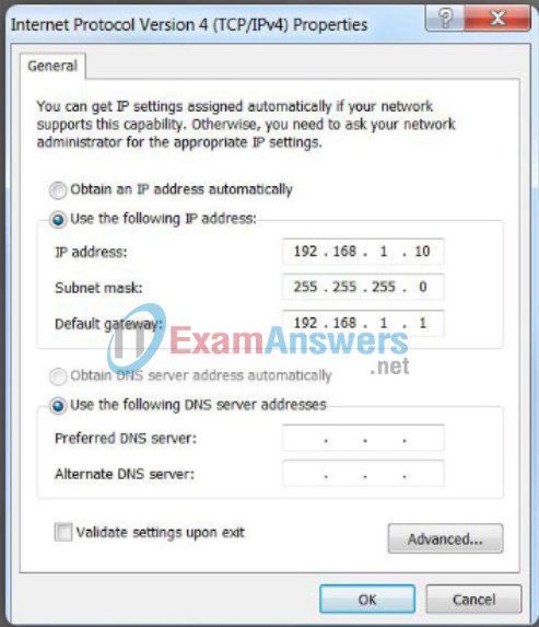
The example in Figure 2 displays the IPv4 address (192.168.1.10), subnet mask (255.255.255.0), and default gateway (192.168.1.1) assigned to a host. The default gateway address is the IP address of the router that the host will use to access remote networks, including the Internet.
IP addresses can be assigned to both physical ports and virtual interfaces on devices. A virtual interface means that there is no physical hardware on the device associated with it.
Connecting End Devices
Devices Requiring IP Addresses
- Computers (work stations, laptops, file servers, web servers)
- Network printers
- VoIP phones
- Security cameras
- Smart phones
- Mobile handheld devices (such as wireless barcode scanners)
Configuring a Static IP Address on a Host
2.3.1.2 Enabling the IOS Image Resilience Feature
Interfaces and Ports
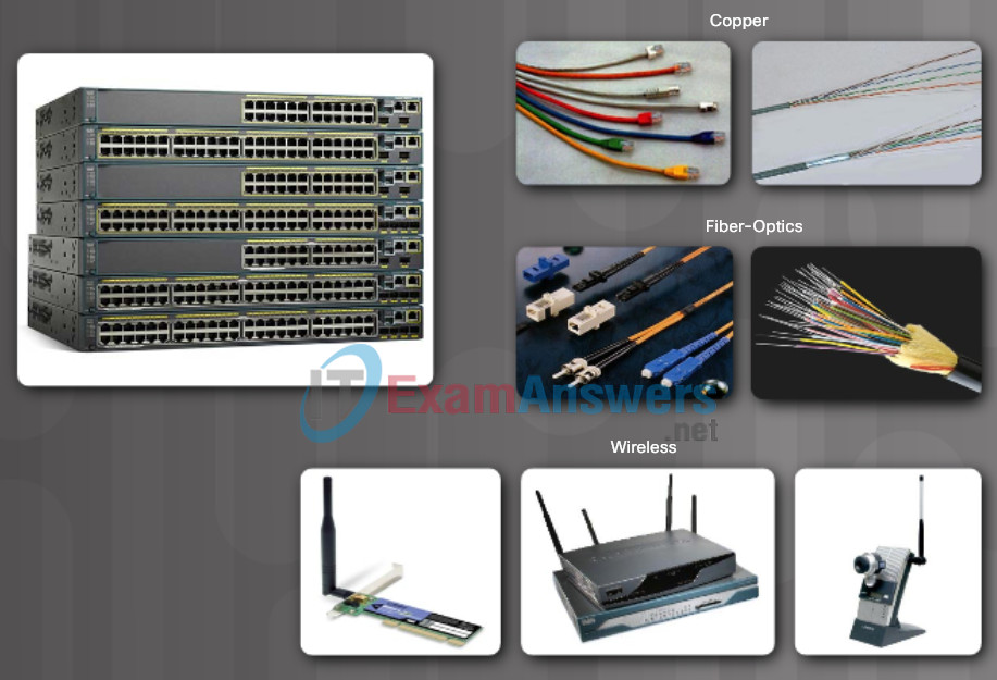
Network communications depend on end user device interfaces, networking device interfaces, and the cables that connect them. Each physical interface has specifications, or standards, that define it. A cable connecting to the interface must be designed to match the physical standards of the interface. Types of network media include twisted-pair copper cables, fiber-optic cables, coaxial cables, or wireless as shown in the figure.
Different types of network media have different features and benefits. Not all network media has the same characteristics and is appropriate for the same purpose. Some of the differences between various types of media include:
- Distance the media can successfully carry a signal
- Environment in which the media is to be installed
- Amount of data and the speed at which it must be transmitted
- Cost of the media and installation
Not only does each link on the Internet require a specific network media type, but each link also requires a particular network technology. For example, Ethernet is the most common local area network (LAN) technology used today. Ethernet ports are found on end-user devices, switch devices, and other networking devices that can physically connect to the network using a cable.
Cisco IOS Layer 2 switches have physical ports for devices to connect. These ports do not support Layer 3 IP addresses. Therefore, switches have one or more switch virtual interfaces (SVIs). These are virtual interfaces because there is no physical hardware on the device associated with it. An SVI is created in software.
The virtual interface provides a means to remotely manage a switch over a network using IPv4. Each switch comes with one SVI appearing in the default configuration “out-of-the-box.” The default SVI is interface VLAN1.
Note: A Layer 2 switch does not need an IP address. The IP address assigned to the SVI is used to remotely access the switch. An IP address is not necessary for the switch to perform its operations.
Interfaces and Ports
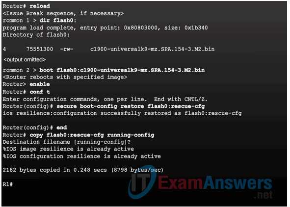
2.3.1.3 The Primary Bootset Image
2.3.1.4 Configuring Secure Copy
Configure the router for server-side SCP with local AAA:
- Configure SSH
- Configure at least one user with privilege level 15
- Enable AAA
- Specify that the local database is to be used for authentication
- Configure command authorization
- Enable SCP server-side functionality
2.3.1.5 Recovering a Router Password
- Connect to the console port.
- Record the configuration register setting.
- Power cycle the router.
- Issue the break sequence.
- Change the default configuration register with the confreg 0x2142 command.
- Reboot the router.
- Press Ctrl-C to skip the initial setup procedure.
- Put the router into privileged EXEC mode.
- Copy the startup configuration to the running configuration.
- Verify the configuration.
- Change the enable secret password.
- Enable all interfaces.
- Change the config-register with the config-register configuration_register_setting.
- Save the configuration changes.
2.3.1.6 Password Recovery
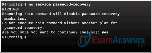
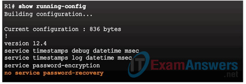
Disable Password Recovery
No Service Password Recovery
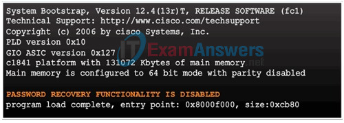
Password Recovery Functionality is Disabled
2.3.2 Secure Management and Reporting
2.3.2.1 Determining the Type of Management Access
Manual IP Address Configuration for End Devices
In order for an end device to communicate over the network, it must be configured with a unique IPv4 address and subnet mask. IP address information can be entered into end devices manually, or automatically using Dynamic Host Configuration Protocol (DHCP).
To manually configure an IPv4 address on a Windows host, open the Control Panel > Network Sharing Center > Change adapter settings and choose the adapter. Next right-click and select Properties to display the Local Area Connection Properties shown in Figure 1.
Highlight Internet Protocol Version 4 (TCP/IPv4) and click Properties to open the Internet Protocol Version 4 (TCP/IPv4) Properties window shown in Figure 2. Configure the IPv4 address and subnet mask information, and default gateway.
Note: The DNS server addresses are the IPv4 addresses of the Domain Name System (DNS) servers, which are used to translate IP addresses to domain names, such as www.cisco.com.
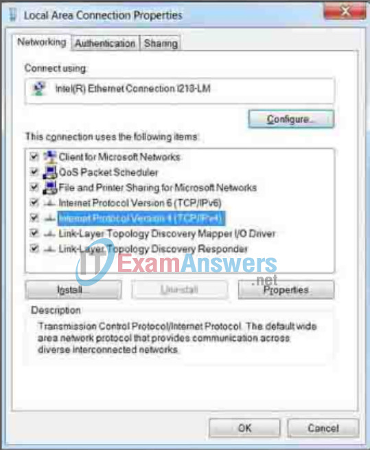
Ethernet Adapter Properties
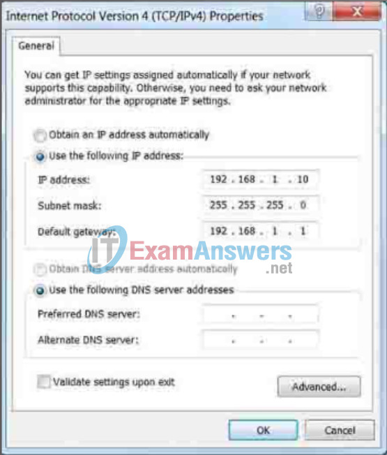
Manually Assigning IPv4 Address Information
2.3.2.2 Out-of-Band and In-Band Access
Automatic IP Address Configuration for End Devices
PCs typically default to using DHCP for automatic IPv4 address configuration. DHCP is a technology that is used in almost every network. The best way to understand why DHCP is so popular is by considering all the extra work that would have to take place without it.
In a network, DHCP enables automatic IPv4 address configuration for every end device that has DHCP enabled. Imagine the amount of time it would consume if every time you connected to the network, you had to manually enter the IPv4 address, the subnet mask, the default gateway, and the DNS server. Multiply that by every user and every device in an organization and you see the problem. Manual configuration also increases the chance of misconfiguration by duplicating another device’s IPv4 address.
As shown in Figure 1, to configure DHCP on a Windows PC, you only need to select “Obtain an IP address automatically” and “Obtain DNS server address automatically”. Your PC will search out a DHCP server and be assigned the address settings necessary to communicate on the network.
It is possible to display the IP configuration settings on a Windows PC by using the ipconfig command at the command prompt. The output will show the IPv4 address, subnet mask, and gateway information received from the DHCP server.
Use the Syntax Checker in Figure 2 to practice displaying the IPv4 address on a Windows PC.
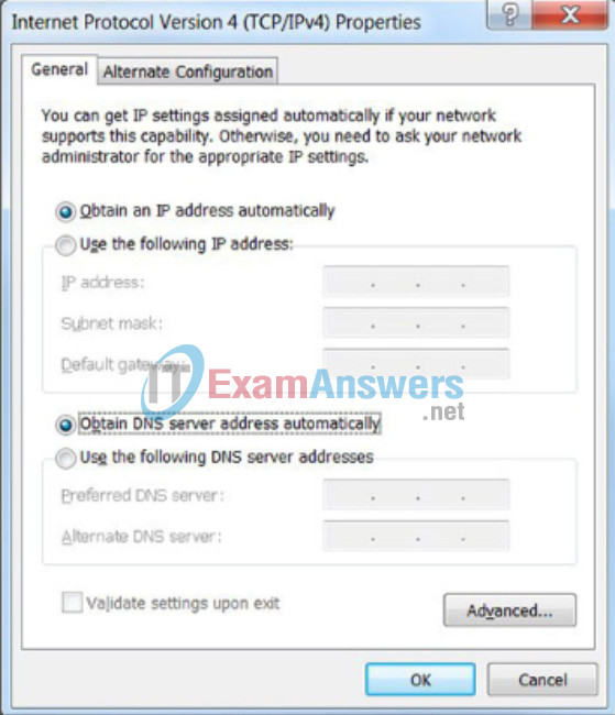
Assigning Dynamic Addresses
Verifying Windows PC IP Configuration
Enter the command to display the IP configuration on a Windows PC.
Microsoft Windows [Version 6.1.7601]
Copyright (c) 2009 Microsoft Corporation. All rights reserved.
C:\> ipconfig

Windows IP Configuration

Ethernet adapter Local Area Connection:

   Connection-specific DNS Suffix . : cisco.com
   Link-local IPv6 Address . . . . . : fe80::b0ef:ca42:af2c:c6c7%16
   IPv4 Address. . . . . . . . . . . : 10.82.240.197
   Subnet Mask . . . . . . . . . . . : 255.255.255.0
   Default Gateway . . . . . . . . . : 10.82.240.198

-------------------------------------
You successfully displayed the IP configuration on a Windows PC.
2.3.3 Using Syslog for Network Security
2.3.3.1 Introduction to Syslog
Interface Addressing Verification
In the same way that you use commands and utilities like ipconfig to verify a PC host’s network configuration, you also use commands to verify the interfaces and address settings of intermediary devices like switches and routers.
2.3.3.2 Syslog Operation
End-to-End Connectivity Test
The ping command can be used to test connectivity to another device on the network or a website on the Internet.
2.3.3.3 Syslog Message
Lab – Building a Simple Network
In this lab, you will complete the following objectives:
- Part 1: Set Up the Network Topology (Ethernet only)
- Part 2: Configure PC Hosts
- Part 3: Configure and Verify Basic Switch Settings
2.3.3.4 Activity – Interpret Syslog Output
Lab – Configuring a Switch Management Address
In this lab, you will complete the following objectives:
- Part 1: Configure a Basic Network Device
- Part 2: Verify and Test Network Connectivity
2.3.3.5 Syslog Systems
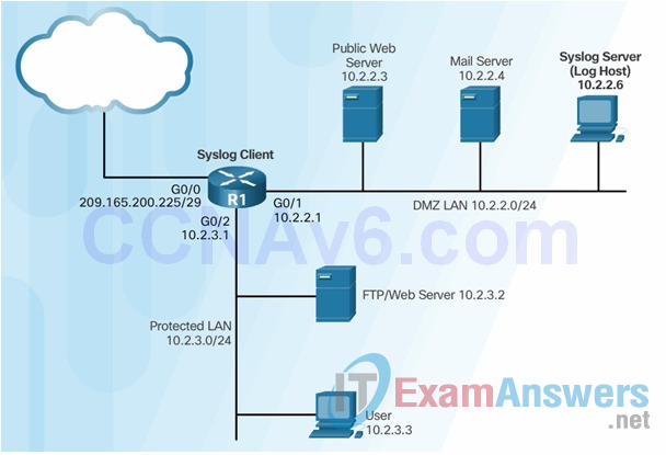
2.3.3.6 Configuring System Logging
Step 1

Step 2 (optional)

Step 3

Step 4

2.3.4 Using SNMP for Network Security
2.3.4.1 Introduction to SNMP

2.3.4.2 Management Information Base (MIB)
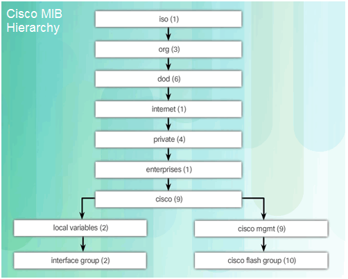
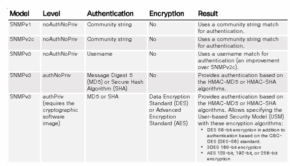
2.3.4.3 SNMP Versions
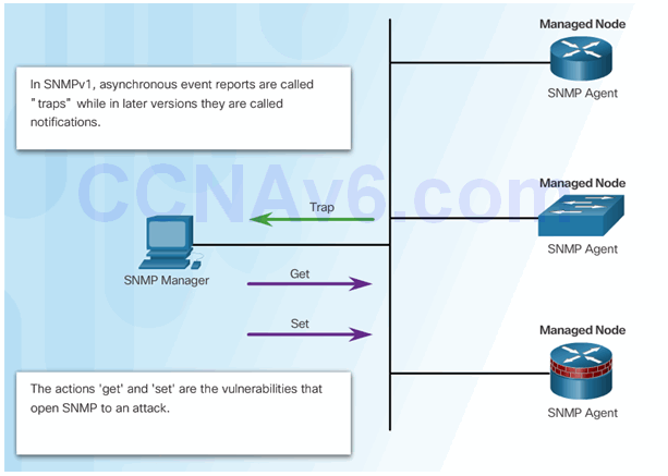
2.3.4.4 SNMP Vulnerabilities
2.3.4.5 SNMPv3
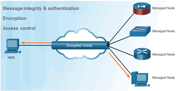
- Transmissions from manager to agent may be authenticated to guarantee the identity of the sender and the integrity and timeliness of a message.
- SNMPv3 messages may be encrypted to ensure privacy.
- Agent may enforce access control to restrict each principal to certain actions on specific portions of data.
2.3.4.6 Configuring SNMPv3 Security
2.3.4.7 Secure SNMPv3 Configuration Example
2.3.4.8 Verifying the SNMPv3 Configuration
2.3.5 Using NTP
2.3.5.1 Network Time Protocol

2.3.5.2 NTP Server
Sample NTP Topology

Sample NTP Configuration on R1
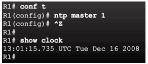
Sample NTP Configuration on R2

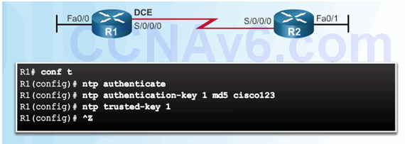
2.3.5.3 NTP Authentication
2.4 Using Automated Security Features
2.4.1 Performing a Security Audit
2.4.1.1 Discovery Protocols CDP and LLDP
Class Activity – Tutor Me
Students will work in pairs. Packet Tracer is required for this activity.
Assume that a new colleague has asked you for an orientation to the Cisco IOS CLI. This colleague has never worked with Cisco devices before.
You explain the basic CLI commands and structure because you want your colleague to understand that the CLI is a simple, yet powerful, command language that can be easily understood and navigated.
Use Packet Tracer and one of the activities available in this chapter as a simple network model (for example, Lab – Configuring a Switch Management Address).
Focus on these areas:
- While the commands are technical, do they resemble any statements from plain English?
- How is the set of commands organized into subgroups or modes? How does an administrator know which mode he or she is currently using?
- What are the individual commands to configure the basic settings of a Cisco device? How would you explain this command in simple terms? Use parallels to real life whenever appropriate.
Suggest how to group different commands together according to their modes so that a minimum number of moves between modes will be needed.

The CLI commands the Cisco IOS!
2.4.1.2 Settings for Protocols and Services
Packet Tracer – Skills Integration Challenge
As a recently hired LAN technician, your network manager has asked you to demonstrate your ability to configure a small LAN. Your tasks include configuring initial settings on two switches using the Cisco IOS and configuring IP address parameters on host devices to provide end-to-end connectivity. You are to use two switches and two hosts/PCs on a cabled and powered network.
Packet Tracer – Skills Integration Challenge Instructions
Packet Tracer – Skills Integration Challenge – PKA
2.4.2 Locking Down a Router Using AutoSecure
2.4.2.1 Cisco AutoSecure
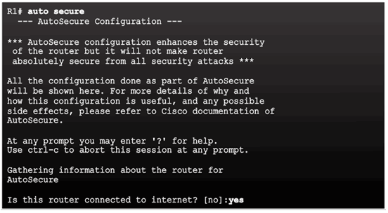
2.4.2.2 Using the Cisco AutoSecure Feature

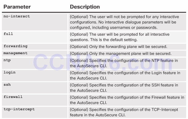
2.4.2.3 Using the auto secure Command
- The auto secure command is entered
- Wizard gathers information about the outside interfaces
- AutoSecure secures the management plane by disabling unnecessary services
- AutoSecure prompts for a banner
- AutoSecure prompts for passwords and enables password and login features
- Interfaces are secured
- Forwarding plane is secured
2.5 Securing the Control Plane
2.5.1 Routing Protocol Authentication
2.5.1.1 Routing Protocol Spoofing
Consequences of protocol spoofing:
- Redirect traffic to create routing loops.
- Redirect traffic so it can be monitored on an insecure link.
- Redirect traffic to discard it.
2.5.1.2 OSPF MD5 Routing Protocol Authentication
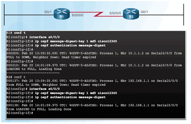
2.5.1.3 OSPF SHA Routing Protocol Authentication
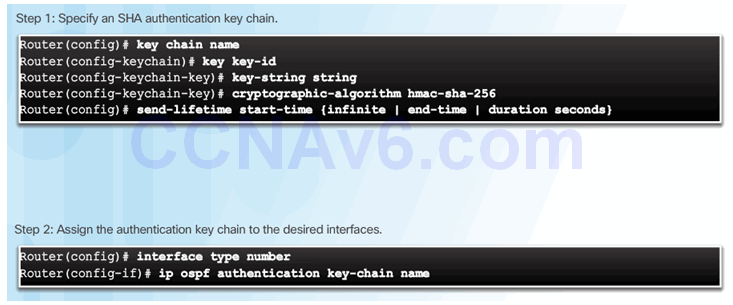
2.5.2 Control Plane Policing
2.5.2.1 Network Device Operations
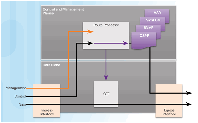
2.5.2.2 Control and Management Plane Vulnerabilities
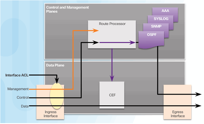
2.5.2.3 CoPP Operation
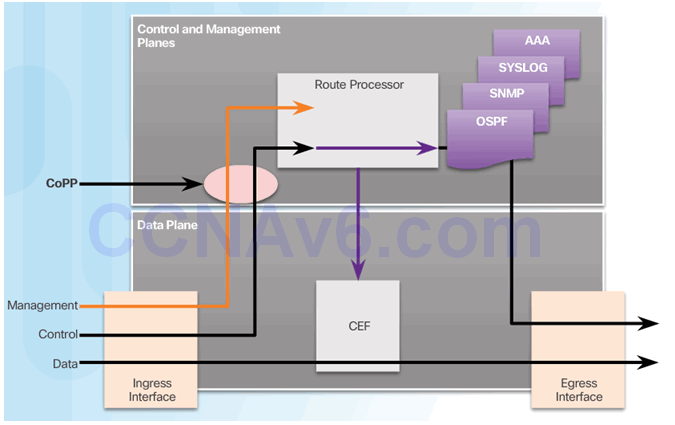
2.5.2.4 Activity – Identify the Features of CoPP
2.5.2.5 Activity – Identify the Network Device Security Feature
2.6 Summary
2.6.1 Conclusion
2.6.1.1 Video Demonstration – Securing the Router
2.6.1.2 Lab – Securing the Router for Administrative Access
2.6.1.2 Lab – Securing the Router for Administrative Access
2.6.1.3 Packet Tracer – Configure Cisco Routers for Syslog, NTP, and SSH Operations
2.6.1.3 Packet Tracer – Configure Cisco Routers for Syslog, NTP, and SSH Operations
2.6.1.4 Chapter 2: Securing Network Devices
