CCNA Security 2.0 Study Material – Chapter 3: Authentication, Authorization, and Accounting
3.0 Introduction
3.0.1 Welcome
3.0.1.1 Chapter 3: Authentication, Authorization, and Accounting
Chapter 3: Network Protocols and Communications
More and more, it is networks that connect us. People communicate online from everywhere. Conversations in classrooms spill into instant message chat sessions, and online debates continue at school. New services are being developed daily to take advantage of the network.
Rather than developing unique and separate systems for the delivery of each new service, the network industry as a whole has adopted a developmental framework that allows designers to understand current network platforms, and maintain them. At the same time, this framework is used to facilitate the development of new technologies to support future communications needs and technology enhancements.
Central to this developmental framework, is the use of generally-accepted models that describe network rules and functions.
Within this chapter, you will learn about these models, as well as the standards that make networks work, and how communication occurs over a network.

3.1 Purpose of the AAA
3.1.1 AAA Overview
3.1.1.1 Authentication without AAA
Communication Fundamentals
A network can be as complex as devices connected across the Internet, or as simple as two computers directly connected to one another with a single cable, and anything in-between. Networks can vary in size, shape, and function. However, simply having a wired or wireless physical connection between end devices is not enough to enable communication. For communication to occur, devices must know “how” to communicate.
People exchange ideas using many different communication methods. However, regardless of the method chosen, all communication methods have three elements in common. The first of these elements is the message source, or sender. Message sources are people, or electronic devices, that need to send a message to other individuals or devices. The second element of communication is the destination, or receiver, of the message. The destination receives the message and interprets it. A third element, called a channel, consists of the media that provides the pathway over which the message travels from source to destination.
Communication begins with a message, or information, that must be sent from a source to a destination. The sending of this message, whether by face-to-face communication or over a network, is governed by rules called protocols. These protocols are specific to the type of communication method occurring. In our day-to-day personal communication, the rules we use to communicate over one medium, like a telephone call, are not necessarily the same as the protocols for using another medium, such as sending a letter.
For example, consider two people communicating face-to-face, as shown in Figure 1. Prior to communicating, they must agree on how to communicate. If the communication is using voice, they must first agree on the language. Next, when they have a message to share, they must be able to format that message in a way that is understandable. For example, if someone uses the English language, but poor sentence structure, the message can easily be misunderstood. Each of these tasks describe protocols put in place to accomplish communication. This is also true of computer communication, as shown in Figure 2.
Many different rules or protocols govern all methods of communication that exist in the world today.
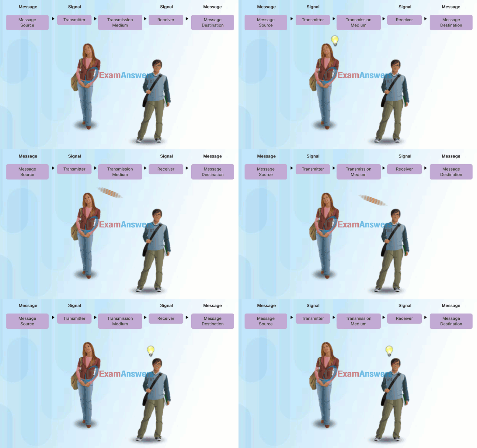
Human Communication
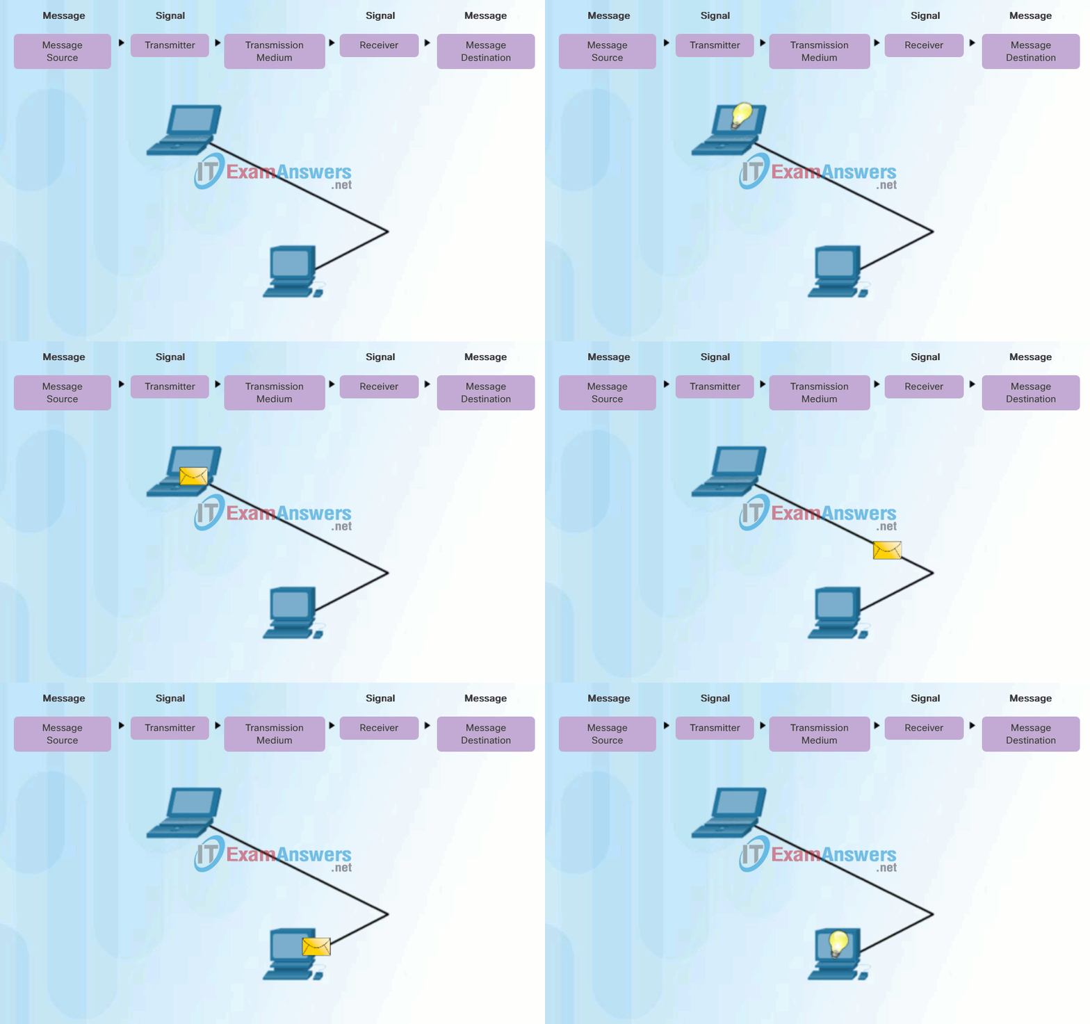
Computer Communication
3.1.1.2 AAA Components
Rule Establishment
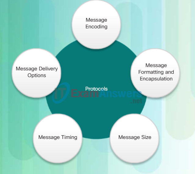
Before communicating with one another, individuals must use established rules or agreements to govern the conversation. For example, consider Figure 1, protocols are necessary for effective communication. These rules, or protocols, must be followed in order for the message to be successfully delivered and understood. Protocols must account for the following requirements:
- An identified sender and receiver
- Common language and grammar
- Speed and timing of delivery
- Confirmation or acknowledgment requirements
The protocols that are used in network communications share many of these fundamental traits. In addition to identifying the source and destination, computer and network protocols define the details of how a message is transmitted across a network. Common computer protocols include the requirements shown in Figure 2. Each of these will be discussed in more detail.
humans communication between govern rules. It is verydifficult tounderstand messages that are not correctly formatted and donot follow the established rules and protocols. A estrutura da gramatica, da lingua, da pontuacao e do sentance faz a configuracao humana compreensivel por muitos individuos diferentes.
Translate
Rules govern communication between humans. It is very difficult to understand messages that are not correctly formatted and do not follow the established rules and protocols. The structure of the grammar, the language, the punctuation and the sentence make the configuration humanly understandable for many different individuals.
3.1.2 AAA Characteristics
3.1.2.1 Authentication Modes
Local AAA Authentication
Server-Based AAA Authentication

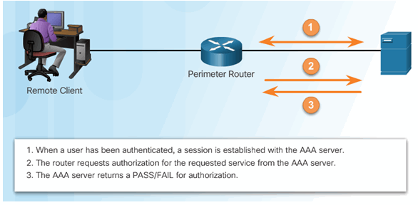
3.1.2.2 Authorization
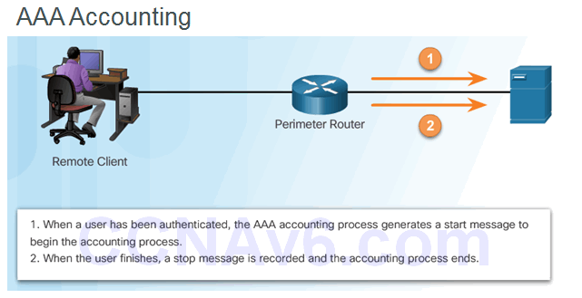
3.1.2.3 Accounting
Types of accounting information:
- Network
- Connection
- EXEC
- System
- Command
- Resource
3.1.2.4 Activity – Identify the Characteristics of AAA
3.2 Local AAA Authentication
3.2.1 Configuring Local AAA Authentication with CLI
3.2.1.1 Authenticating Administrative Access
Rules that Govern Communications
A group of inter-related protocols necessary to perform a communication function is called a protocol suite. Protocol suites are implemented by hosts and networking devices in software, hardware or both.
One of the best ways to visualize how the protocols within a suite interact is to view the interaction as a stack. A protocol stack shows how the individual protocols within a suite are implemented. The protocols are viewed in terms of layers, with each higher level service depending on the functionality defined by the protocols shown in the lower levels. The lower layers of the stack are concerned with moving data over the network and providing services to the upper layers, which are focused on the content of the message being sent.
As the figure shows, we can use layers to describe the activity occurring in our face-to-face communication example. At the bottom, the physical layer, we have two people, each with a voice that can say words out loud. In the middle, the rules layer, we have an agreement to speak in a common language. At the top, the content layer, there are words that are actually spoken. This is the content of the communication.
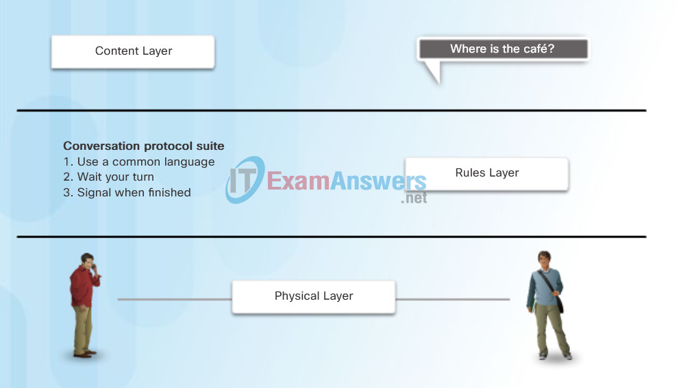
Protocol Suite
Protocol suites are sets of rules that work together to help solve a problem.
3.2.1.2 Authentication Methods
Network Protocols
At the human level, some communication rules are formal and others are simply understood based on custom and practice. For devices to successfully communicate, a network protocol suite must describe precise requirements and interactions. Networking protocols define a common format and set of rules for exchanging messages between devices. Some common networking protocols are Hypertext Transfer Protocol (HTTP), Transmission Control Protocol (TCP), and Internet Protocol (IP).
Note: IP in this course refers to both the IPv4 and IPv6 protocols. IPv6 is the most recent version of IP and the replacement for the more common IPv4.
The figures illustrate networking protocols that describe the following processes:
- How the message is formatted or structured, as shown in Figure 1.
- The process by which networking devices share information about pathways with other networks, as shown in Figure 2.
- How and when error and system messages are passed between devices, as shown in Figure 3.
- The setup and termination of data transfer sessions, as shown in Figure 4.
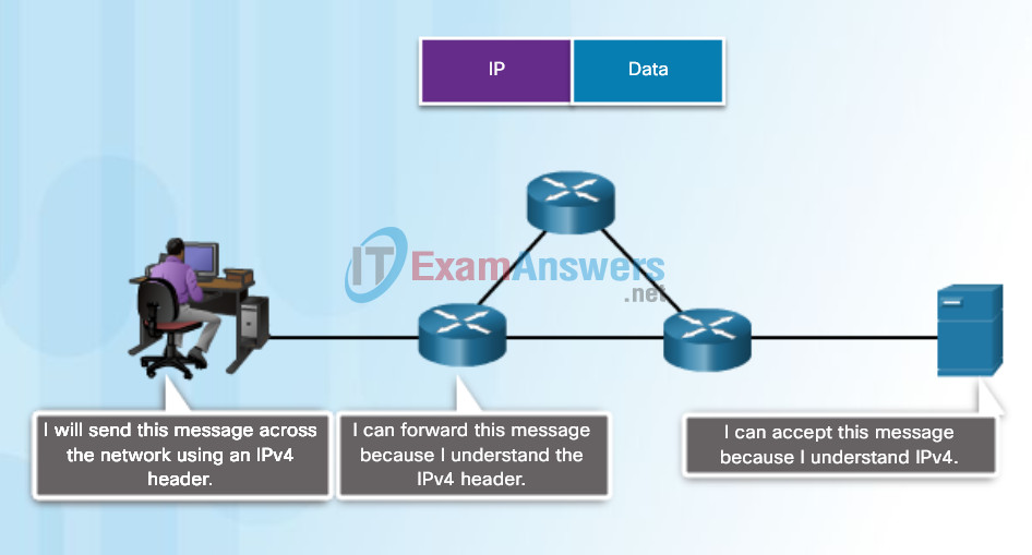
The format or structure of the communication pieces.
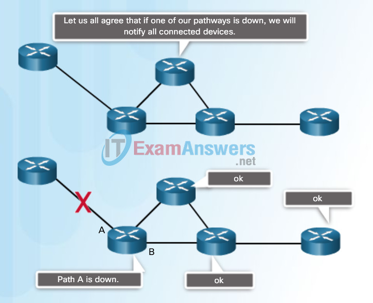
The process by which networking devices share information about pathways to other networks
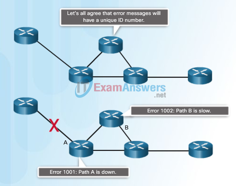
How and when error and system messages are passed between devices
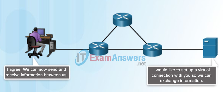
The setting up and termination of data transfer sessions
3.2.1.3 Default and Named Methods
Protocol Interaction
Communication between a web server and web client is an example of an interaction between several protocols. The protocols shown in the figure include:
HTTP – is an application protocol that governs the way a web server and a web client interact. HTTP defines the content and formatting of the requests and responses that are exchanged between the client and server. Both the client and the web server software implement HTTP as part of the application. HTTP relies on other protocols to govern how the messages are transported between the client and server.
TCP – is the transport protocol that manages the individual conversations. TCP divides the HTTP messages into smaller pieces, called segments. These segments are sent between the web server and client processes running at the destination host. TCP is also responsible for controlling the size and rate at which messages are exchanged between the server and the client.
IP – is responsible for taking the formatted segments from TCP, encapsulating them into packets, assigning them the appropriate addresses, and delivering them to the destination host.
Ethernet – is a network access protocol that describes two primary functions: communication over a data link and the physical transmission of data on the network media. Network access protocols are responsible for taking the packets from IP and formatting them to be transmitted over the media.
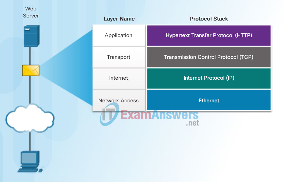
Interaction of Protocols
3.2.1.4 Fine-Tuning the Authentication Configuration
Command Syntax

Display Locked Out Users

Show Unique ID of a Session

3.2.2 Troubleshooting Local AAA Authentication
3.2.2.1 Debug Options
Protocol Suites and Industry Standards
A protocol suite is a set of protocols that work together to provide comprehensive network communication services. A protocol suite may be specified by a standards organization or developed by a vendor. Protocol suites, like the four shown in the figure, can be a bit overwhelming. However, this course will only cover the protocols of the TCP/IP protocol suite.
The TCP/IP protocol suite is an open standard, meaning these protocols are freely available to the public, and any vendor is able to implement these protocols on their hardware or in their software.
A standards-based protocol is a process that has been endorsed by the networking industry and approved by a standards organization. The use of standards in developing and implementing protocols ensures that products from different manufacturers can interoperate successfully. If a protocol is not rigidly observed by a particular manufacturer, their equipment or software may not be able to successfully communicate with products made by other manufacturers.
Some protocols are proprietary which means one company or vendor controls the definition of the protocol and how it functions. Examples of proprietary protocols are AppleTalk and Novell Netware, which are legacy protocol suites. It is not uncommon for a vendor (or group of vendors) to develop a proprietary protocol to meet the needs of its customers and later assist in making that proprietary protocol an open standard.
For example, click here to view a video presentation by Bob Metcalfe describing the story of how Ethernet was developed.
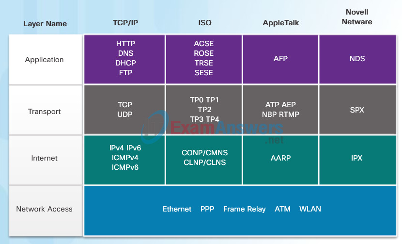
Protocol Suites and Industry Standards
3.2.2.2 Debugging AAA Authentication
Development of TCP/IP
The first packet switching network and predecessor to today’s Internet was the Advanced Research Projects Agency Network (ARPANET), which came to life in 1969 by connecting mainframe computers at four locations. ARPANET was funded by the U.S. Department of Defense for use by universities and research laboratories.
3.3 Server-Based AAA
3.3.1 Server-Based AAA Characteristics
3.3.1.1 Comparing Local AAA and Server-Based AAA Implementations
Message Segmentation
In theory, a single communication, such as a music video or an email message, could be sent across a network from a source to a destination as one massive, uninterrupted stream of bits. If messages were actually transmitted in this manner, it would mean that no other device would be able to send or receive messages on the same network while this data transfer was in progress. These large streams of data would result in significant delays. Further, if a link in the interconnected network infrastructure failed during the transmission, the complete message would be lost and have to be retransmitted in full.
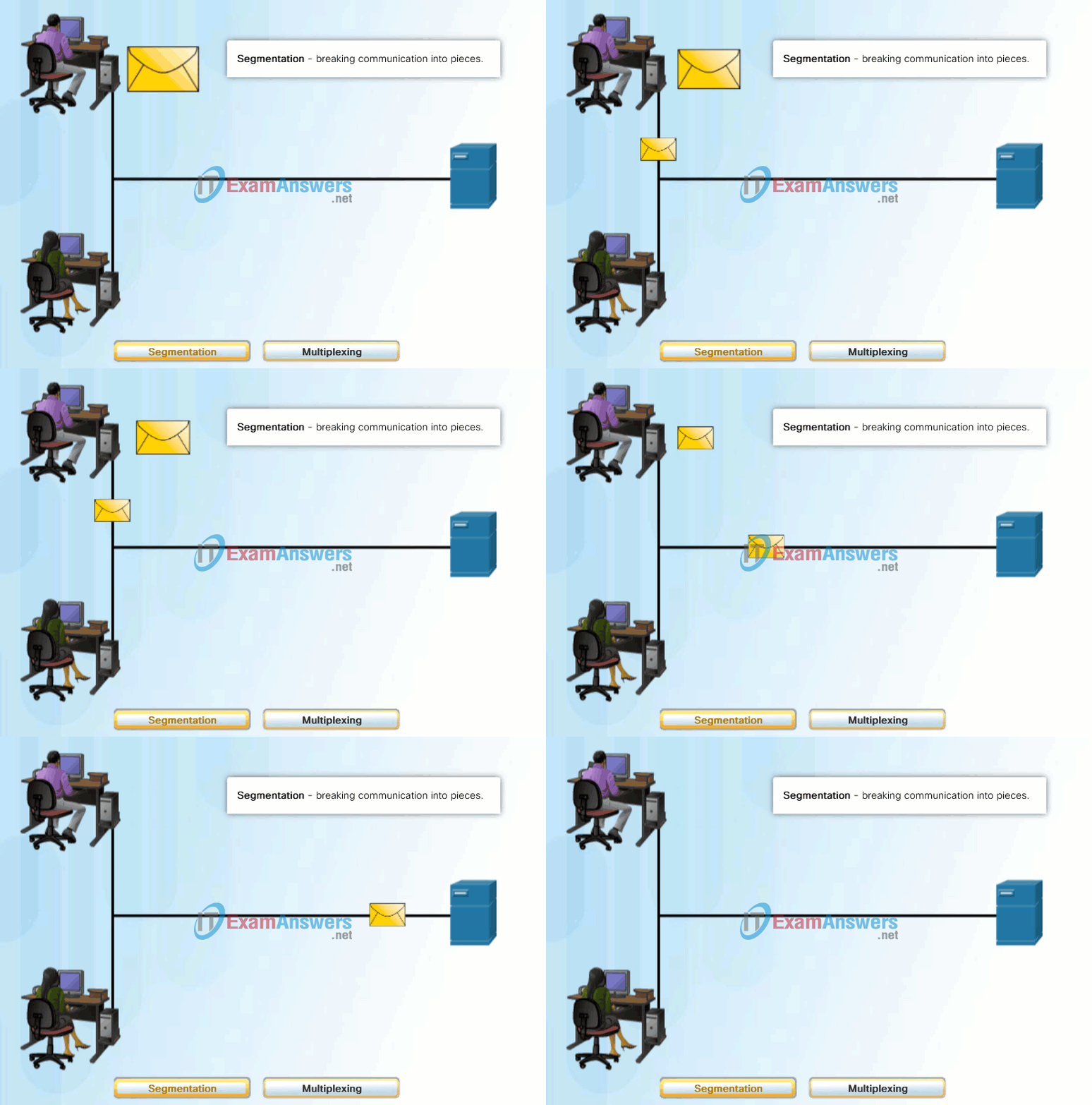
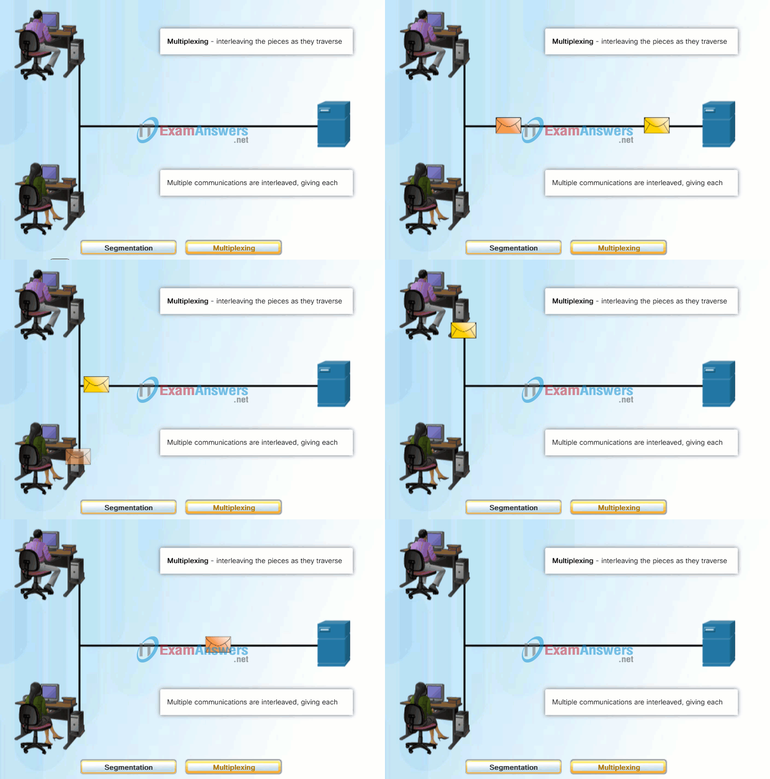
A better approach is to divide the data into smaller, more manageable pieces to send over the network. This division of the data stream into smaller pieces is called segmentation. Segmenting messages has two primary benefits:
- By sending smaller individual pieces from source to destination, many different conversations can be interleaved on the network, called multiplexing. Click each button in Figure 1, and then click the Play button to view the animations of segmentation and multiplexing.
- Segmentation can increase the efficiency of network communications. If part of the message fails to make it to the destination, due to failure in the network or network congestion, only the missing parts need to be retransmitted.
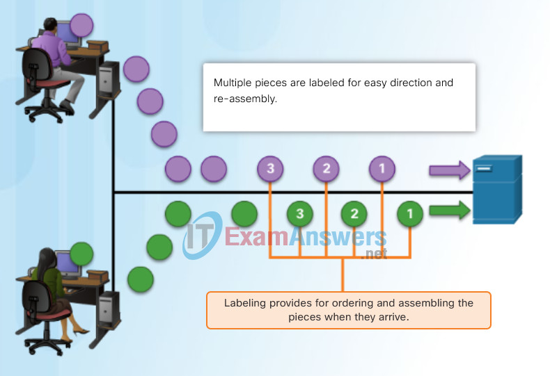
The challenge to using segmentation and multiplexing to transmit messages across a network is the level of complexity that is added to the process. Imagine if you had to send a 100-page letter, but each envelope would only hold one page. The process of addressing, labeling, sending, receiving, and opening the entire 100 envelopes would be time-consuming for both the sender and the recipient.
In network communications, each segment of the message must go through a similar process to ensure that it gets to the correct destination and can be reassembled into the content of the original message, as shown in Figure 2.
3.3.1.2 Introducing Cisco Secure Access Control System
Protocol Data Units
As application data is passed down the protocol stack on its way to be transmitted across the network media, various protocol information is added at each level. This is known as the encapsulation process.
The form that a piece of data takes at any layer is called a protocol data unit (PDU). During encapsulation, each succeeding layer encapsulates the PDU that it receives from the layer above in accordance with the protocol being used. At each stage of the process, a PDU has a different name to reflect its new functions. Although there is no universal naming convention for PDUs, in this course, the PDUs are named according to the protocols of the TCP/IP suite, as shown in the figure. Click each PDU in the figure for more information.
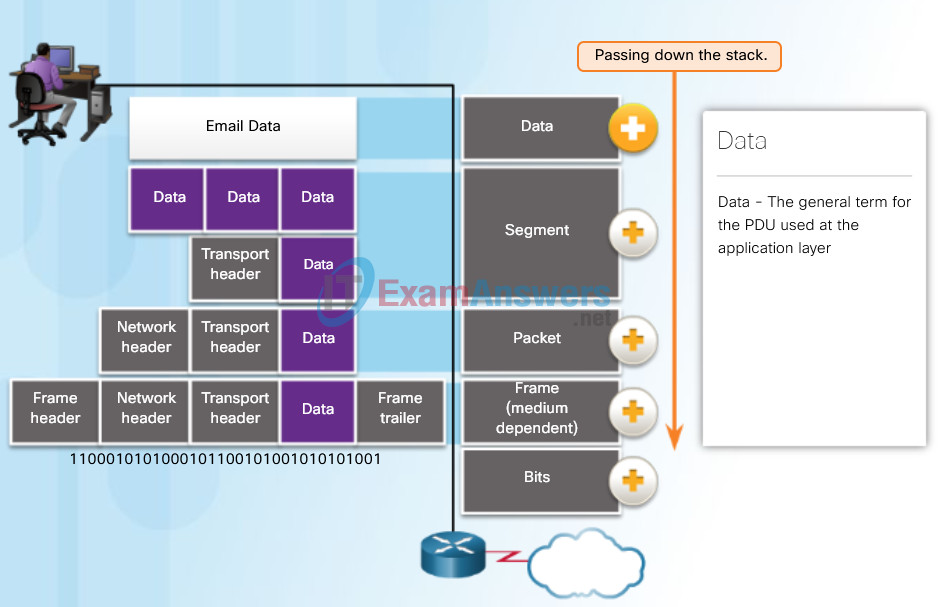
Encapsulation
- Data – The general term for the PDU used at the application layer
- Segment – Transport layer PDU
- Packet – Network layer PDU
- Frame (medium dependent) – Data Link layer PDU
- Bits – A Physical layer PDU used when physically transmitting data over the medium
3.3.2 Server-Based AAA Communications Protocols
3.3.2.1 Introducing TACACS+ and RADIUS
Network Addresses
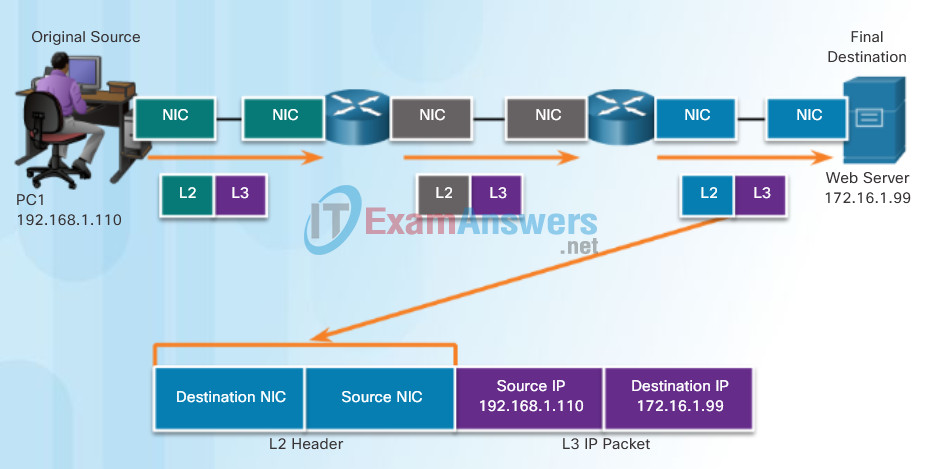
The network and data link layers are responsible for delivering the data from the source device to the destination device. As shown in Figure 1, protocols at both layers contain a source and destination address, but their addresses have different purposes.
- Network layer source and destination addresses – Responsible for delivering the IP packet from the original source to the final destination, either on the same network or to a remote network.
- Data link layer source and destination addresses – Responsible for delivering the data link frame from one network interface card (NIC) to another NIC on the same network.
An IP address is the network layer, or Layer 3, logical address used to deliver the IP packet from the original source to the final destination, as shown in Figure 2.
The IP packet contains two IP addresses:
- Source IP address – The IP address of the sending device, the original source of the packet.
- Destination IP address – The IP address of the receiving device, the final destination of the packet.

Network Addresses and Data Link Addresses
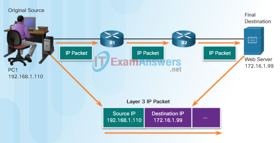
Layer 3 Network Addresses
3.3.2.2 TACACS+ Authentication
Data Link Addresses
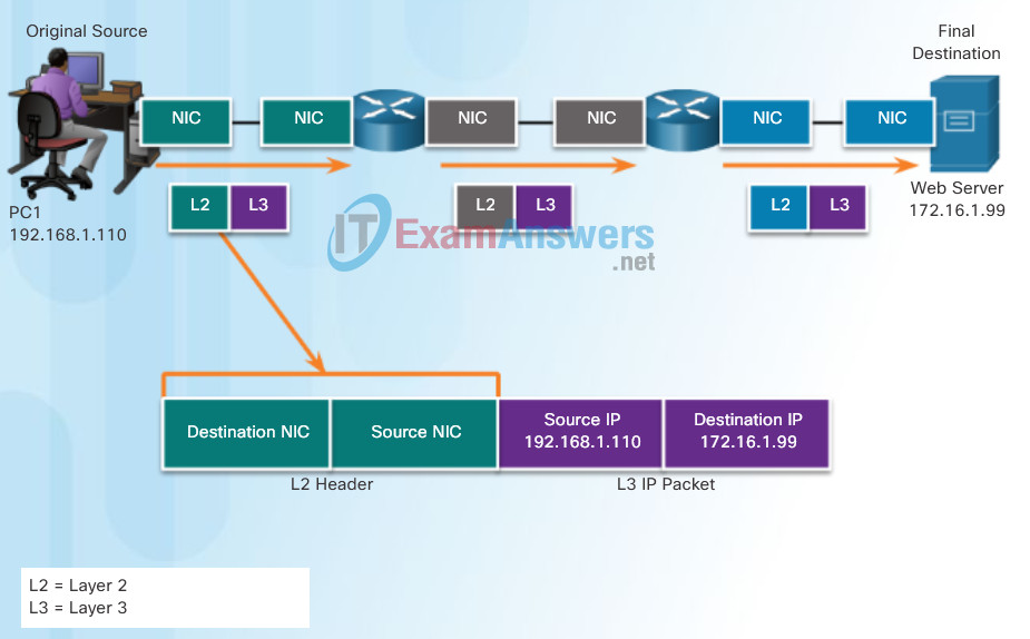
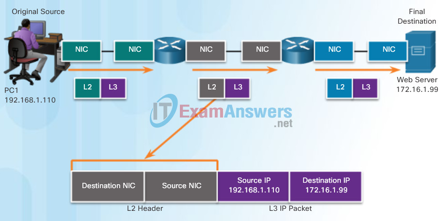
The data link, or Layer 2, physical address has a different role. The purpose of the data link address is to deliver the data link frame from one network interface to another network interface on the same network. This process is illustrated in Figures 1 through 3.
Before an IP packet can be sent over a wired or wireless network, it must be encapsulated in a data link frame so it can be transmitted over the physical medium.
As the IP packet travels from host-to-router, router-to-router, and finally router-to-host, at each point along the way the IP packet is encapsulated in a new data link frame. Each data link frame contains the source data link address of the NIC card sending the frame, and the destination data link address of the NIC card receiving the frame.
The Layer 2, data link protocol is only used to deliver the packet from NIC-to-NIC on the same network. The router removes the Layer 2 information as it is received on one NIC and adds new data link information before forwarding out the exit NIC on its way towards the final destination.
The IP packet is encapsulated in a data link frame that contains data link information, including a:
- Source data link address – The physical address of the device’s NIC that is sending the data link frame.
- Destination data link address – The physical address of the NIC that is receiving the data link frame. This address is either the next hop router or of the final destination device.
The data link frame also contains a trailer which will be discussed in later chapters.
3.3.2.3 RADIUS Authentication
Devices on the Same Network
To understand how devices communicate within a network, it is important to understand the roles of both the network layer addresses and the data link addresses.
Role of the Network Layer Addresses
The network layer addresses, or IP addresses, indicate the original source and final destination. An IP address contains two parts:
- Network portion – The left-most part of the address that indicates which network the IP address is a member. All devices on the same network will have the same network portion of the address.
- Host portion – The remaining part of the address that identifies a specific device on the network. The host portion is unique for each device on the network.
Note: The subnet mask is used to identify the network portion of an address from the host portion. The subnet mask is discussed in later chapters.
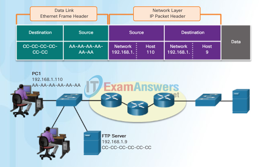
In this example we have a client computer, PC1, communicating with an FTP server on the same IP network.
- Source IP address – The IP address of the sending device, the client computer PC1: 192.168.1.110.
- Destination IP address – The IP address of the receiving device, FTP server: 192.168.1.9.
Notice in the figure that the network portion of both the source IP address and destination IP address are on the same network.
Role of the Data Link Layer Addresses
When the sender and receiver of the IP packet are on the same network, the data link frame is sent directly to the receiving device. On an Ethernet network, the data link addresses are known as Ethernet (Media Access Control) addresses. MAC addresses are physically embedded on the Ethernet NIC.
- Source MAC address – This is the data link address, or the Ethernet MAC address, of the device that sends the data link frame with the encapsulated IP packet. The MAC address of the Ethernet NIC of PC1 is AA-AA-AA-AA-AA-AA, written in hexadecimal notation.
- Destination MAC address – When the receiving device is on the same network as the sending device, this is the data link address of the receiving device. In this example, the destination MAC address is the MAC address of the FTP server: CC-CC-CC-CC-CC-CC, written in hexadecimal notation.
The frame with the encapsulated IP packet can now be transmitted from PC1 directly to the FTP server.
Communicating with a Device on the Same Network
3.3.2.4 Integration of TACACS+ and ACS
Devices on a Remote Network
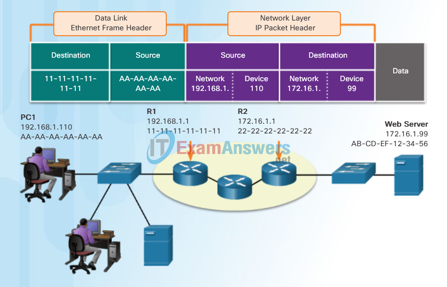
But what are the roles of the network layer address and the data link layer address when a device is communicating with a device on a remote network? In this example we have a client computer, PC1, communicating with a server, named Web Server, on a different IP network.
Role of the Network Layer Addresses
When the sender of the packet is on a different network from the receiver, the source and destination IP addresses will represent hosts on different networks. This will be indicated by the network portion of the IP address of the destination host.
- Source IP address – The IP address of the sending device, the client computer PC1: 192.168.1.110.
- Destination IP address – The IP address of the receiving device, the server, Web Server: 172.16.1.99.
Notice in the figure that the network portion of the source IP address and destination IP address are on different networks.
Role of the Data Link Layer Addresses
When the sender and receiver of the IP packet are on different networks, the Ethernet data link frame cannot be sent directly to the destination host because the host is not directly reachable in the network of the sender. The Ethernet frame must be sent to another device known as the router or default gateway. In our example, the default gateway is R1. R1 has an Ethernet data link address that is on the same network as PC1. This allows PC1 to reach the router directly.
- Source MAC address – The Ethernet MAC address of the sending device, PC1. The MAC address of the Ethernet interface of PC1 is AA-AA-AA-AA-AA-AA.
- Destination MAC address – When the receiving device, the destination IP address, is on a different network from the sending device, the sending device uses the Ethernet MAC address of the default gateway or router. In this example, the destination MAC address is the MAC address of R1’s Ethernet interface, 11-11-11-11-11-11. This is the interface that is attached to the same network as PC1.
The Ethernet frame with the encapsulated IP packet can now be transmitted to R1. R1 forwards the packet to the destination, Web Server. This may mean that R1 forwards the packet to another router or directly to Web Server if the destination is on a network connected to R1.
It is important that the IP address of the default gateway be configured on each host on the local network. All packets to a destination on remote networks are sent to the default gateway. Ethernet MAC addresses and the default gateway are discussed in later chapters.
Communicating with a Device on a Remote Network
3.3.2.5 Integration of AAA with Active Directory
3.3.2.6 Integration of AAA with Identity Service Engine
3.3.2.7 Activity – Identify the AAA Communication Protocol
3.4 Server-Based AAA Authentication
3.4.1 Configuring Server-Based Authentication
3.4.1.1 Steps for Configuring Server-Based AAA Authentication
Lab – Installing Wireshark
Wireshark is a software protocol analyzer, or “packet sniffer” application, used for network troubleshooting, analysis, software and protocol development, and education. Wireshark is used throughout the course to demonstrate network concepts. In this lab, you will download and install Wireshark.
3.4.1.2 Configuring TACACS+ Servers
Lab – Using Wireshark to View Network Traffic
In this lab, you will use Wireshark to capture and analyze traffic.
3.4.1.3 Configuring RADIUS Servers
Class Activity – Guaranteed to Work!
You have just completed the Chapter 3 content regarding network protocols and standards.
Assuming you resolved the beginning of this chapter’s modeling activity, how would you compare the following steps taken to design a communications system to the networking models used for communications?
- Establishing a language to communicate
- Dividing the message into small steps, delivered a little at a time, to facilitate understanding of the problem
- Checking to see if the data has been delivered fully and correctly
- Timing needed to ensure quality data communication and delivery
Using network protocols and standards facilitates quality data delivery in a timely manner.
3.4.1.4 Configure Authentication to Use the AAA Server
Chapter 3: Network Protocols and Communications
Data networks are systems of end devices, intermediary devices, and the media connecting them. For communication to occur, these devices must know how to communicate.
These devices must comply with communication rules and protocols. TCP/IP is an example of a protocol suite. Most protocols are created by a standards organization such as the IETF or IEEE. The Institute of Electrical and Electronics Engineers is a professional organization for those in the electrical engineering and electronics fields. ISO, the International Organization for Standardization, is the world’s largest developer of international standards for a wide variety of products and services.
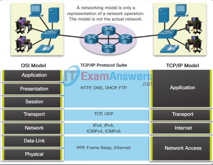
The most widely-used networking models are the OSI and TCP/IP models. Associating the protocols that set the rules of data communications with the different layers of these models is useful in determining which devices and services are applied at specific points as data passes across LANs and WANs.
Data that passes down the stack of the OSI model is segmented into pieces and encapsulated with addresses and other labels. The process is reversed as the pieces are de-encapsulated and passed up the destination protocol stack. The OSI model describes the processes of encoding, formatting, segmenting, and encapsulating data for transmission over the network.
The TCP/IP protocol suite is an open standard protocol that has been endorsed by the networking industry and ratified, or approved, by a standards organization. The Internet Protocol Suite is a suite of protocols required for transmitting and receiving information using the Internet.
Protocol Data Units (PDUs) are named according to the protocols of the TCP/IP suite: data, segment, packet, frame, and bits.
Applying models allows individuals, companies, and trade associations to analyze current networks and plan the networks of the future.
3.4.2 Troubleshooting Server-Based AAA Authentication
3.4.2.1 Monitoring Authentication Traffic
Troubleshooting Server-Based AAA Authentication

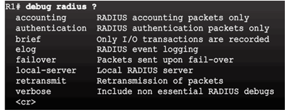
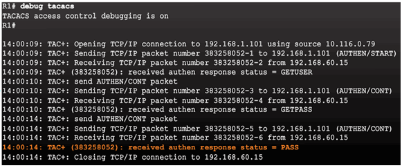
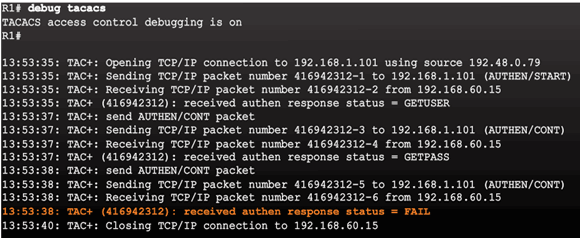
3.4.2.2 Debugging TACACS+ and RADIUS
Troubleshooting RADIUS
Troubleshooting TACACS+

AAA Server-Based Authentication Success
AAA Server-Based Authentication Failure
3.4.2.3 Video Demonstration – Configure a Cisco Router to Access a AAA RADIUS Server
3.5 Server-Based AAA Authorization and Accounting
3.5.1 Configuring Server-Based AAA Authorization
3.5.1.1 Introduction to Server-Based AAA Authorization
Authentication vs. Authorization
- Authentication ensures a device or end-user is legitimate
- Authorization allows or disallows authenticated users access to certain areas and programs on the network.
TACACS+ vs. RADIUS
- TACACS+ separates authentication from authorization
- RADIUS does not separate authentication from authorization
3.5.1.2 AAA Authorization Configuration
Command Syntax

Authorization Method Lists
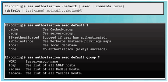
Example AAA Authorization

3.5.2 Configuring Server-Based AAA Accounting
3.5.2.1 Introduction to Server-Based AAA Accounting
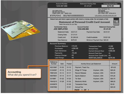
3.5.2.2 AAA Accounting Configuration
Command Syntax
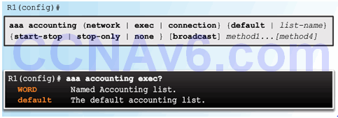
Accounting Method Lists
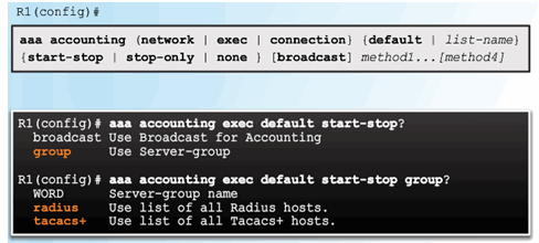
Example AAA Accounting

3.5.3 802.1X Authentication
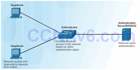
3.5.3.1 Security Using 802.1X Port-Based Authentication
802.1X Roles
802.1X Message Exchange

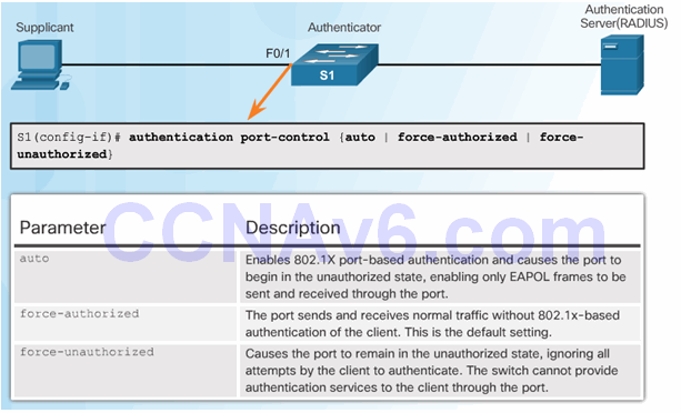
3.5.3.2 802.1X Port Authorization State
Command Syntax for dot1x port-control
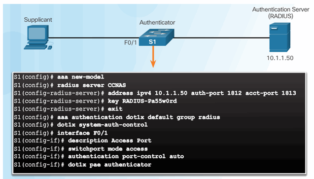
3.5.3.3 Configuring 802.1X
3.6 Summary 3.6.1 Conclusion
3.6.1 Conclusion
3.6.1.1 Lab – Securing Administrative Access Using AAA and RADIUS
3.6.1.1 Lab – Securing Administrative Access Using AAA and RADIUS
3.6.1.2 Packet Tracer – Configure AAA Authentication on Cisco Routers
3.6.1.2 Packet Tracer – Configure AAA Authentication on Cisco Routers
3.6.1.3 Authentication, Authorization, and Accounting
