10.0 Introduction
10.0.1 Welcome
10.0.1.1 Chapter 10: Advanced Cisco Adaptive Security Appliance
Applications, such as web browsers, online gaming, chatting with and emailing friends, enable us to send and receive data with relative ease. Typically we can access and use these applications without knowing how they work. However, for network professionals, it is important to know how an application is able to format, transmit and interpret messages that are sent and received across the network.
Visualizing the mechanisms that enable communication across the network is made easier if we use the layered framework of the OSI model.
In this chapter, we will explore the role of the application layer and how the applications, services, and protocols within the application layer make robust communication across data networks possible.
10.1 ASA Security Device Manager
10.1.1 Introduction to ASDM
10.1.1.1 Overview of ASDM
The Application Layer
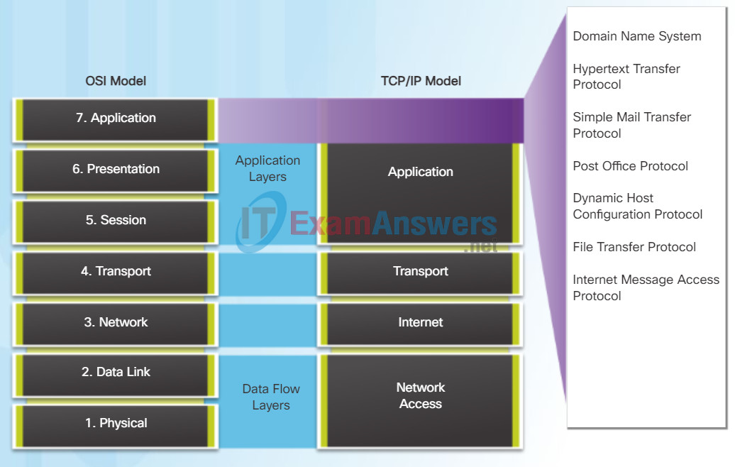
The application layer is closest to the end user. As shown in the figure, it is the layer that provides the interface between the applications used to communicate and the underlying network over which messages are transmitted. Application layer protocols are used to exchange data between programs running on the source and destination hosts.
The upper three layers of the OSI model (application, presentation, and session) define functions of the single TCP/IP application layer.
There are many application layer protocols, and new protocols are always being developed. Some of the most widely known application layer protocols include Hypertext Transfer Protocol (HTTP), File Transfer Protocol (FTP), Trivial File Transfer Protocol (TFTP), Internet Message Access Protocol (IMAP), and Domain Name System (DNS) protocol.
10.1.1.2 Preparing for ASDM
The Presentation Layer
The presentation layer has three primary functions:
- Formatting, or presenting, data at the source device into a compatible form for receipt by the destination device
- Compressing data in a way that can be decompressed by the destination device
- Encrypting data for transmission and decrypting data upon receipt
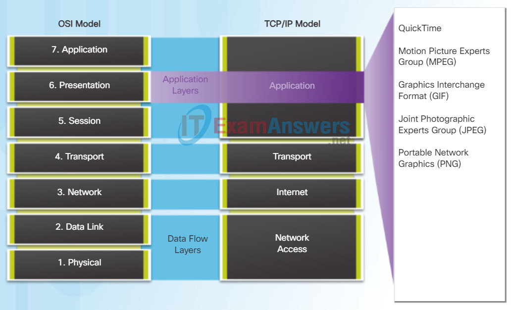
As shown in the figure, the presentation layer formats data for the application layer, and it sets standards for file formats. Some well-known standards for video include QuickTime and Motion Picture Experts Group (MPEG). Some well-known graphic image formats that are used on networks are Graphics Interchange Format (GIF), Joint Photographic Experts Group (JPEG), and Portable Network Graphics (PNG) format.
The Session Layer
As the name implies, functions at the session layer create and maintain dialogs between source and destination applications. The session layer handles the exchange of information to initiate dialogs, keep them active, and to restart sessions that are disrupted or idle for a long period of time.
10.1.1.3 Starting ASDM
TCP/IP Application Layer Protocols
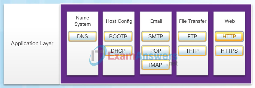
The TCP/IP application protocols specify the format and control information necessary for many common Internet communication functions. Click each application protocol in the figure to learn more about them.
Application layer protocols are used by both the source and destination devices during a communication session. For the communications to be successful the application layer protocols implemented on the source and destination host must be compatible.
Domain Name System (or Service) – TCP, UDP 53:
- Translates domain names, such as cisco.com, into IP addresses
Bootstrap Protocol – UDP client 68, server 67:
- Enables a diskless workstation to discover its own IP address, the IP address of a BOOTP server on the network, and a file to be loaded into memory to boot the machine
- BOOTP is being superseded by DHCP
Dynamic Host Configuration Protocol – UDP client 68, server 67:
- Dynamically assigns IP addresses to client stations at start-up
- Allows the addresses to be re-used when no longer needed
Simple Mail Transfer Protocol – TCP 25:
- Enables clients to send email to a mail server
- Enables servers to send email to other servers
Post Office Protocol – TCP 110:
- Enables clients to retrieve email from a mail server
- Downloads email from the mail server to the desktop
Internet Message Access Protocol – TCP 143:
- Enables clients to access email stored on a mail server
- Maintains email on the server
File Transfer Protocol – TCP 20 to 21:
- Sets rules that enable a user on one host to access and transfer files to and from another host over a network
- A reliable, connection-oriented, and acknowledged file delivery protocol
Trivial File Transfer Protocol – UDP 69:
- A simple, connectionless file transfer protocol
- A best-effort, unacknowledged file delivery protocol
- Utilizes less overhead than FTP
Hypertext Transfer Protocol – TCP 80, 8080:
- Set of rules for exchanging text, graphic images, sound, video, and other multimedia files on the World Wide Web
Hypertext Transfer Protocol Secure – TCP, UDP 443:
- The browser uses encryption to secure HTTP communications
- Authenticates the website to which you are connecting your browser
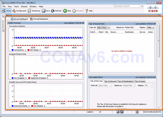
10.1.1.4 ASDM Home Page Dashboards
ASDM Device Dashboard Page
ASDM Firewall Dashboard Page
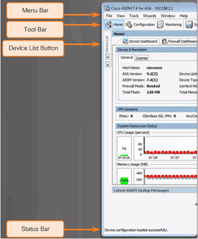
10.1.1.5 ASDM Page Elements
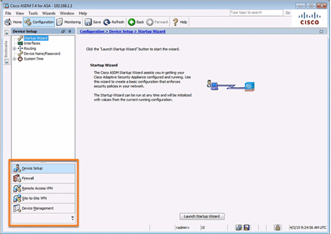
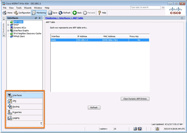
10.1.1.6 ASDM Configuration and Monitoring Views
Configuration View
Monitoring View
10.1.1.7 Video Demonstration – Configure and Access ASDM on an ASA 5505
10.1.2 ASDM Wizard Menu
10.1.2.1 ASDM Wizards
In the client-server model, the device requesting the information is called a client and the device responding to the request is called a server. Client and server processes are considered to be in the application layer. The client begins the exchange by requesting data from the server, which responds by sending one or more streams of data to the client. Application layer protocols describe the format of the requests and responses between clients and servers. In addition to the actual data transfer, this exchange may also require user authentication and the identification of a data file to be transferred.
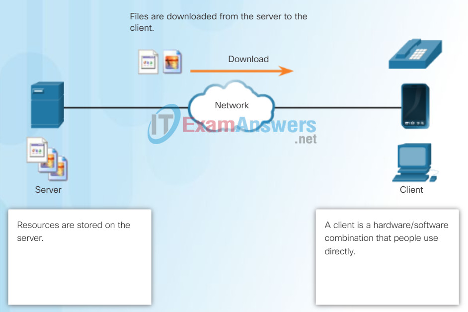
File Server and Client Download Example
One example of a client-server network is using an ISP’s email service to send, receive and store email. The email client on a home computer issues a request to the ISP’s email server for any unread mail. The server responds by sending the requested email to the client. As shown in the figure, data transfer from a client to a server is referred to as an upload and data from a server to a client as a download.
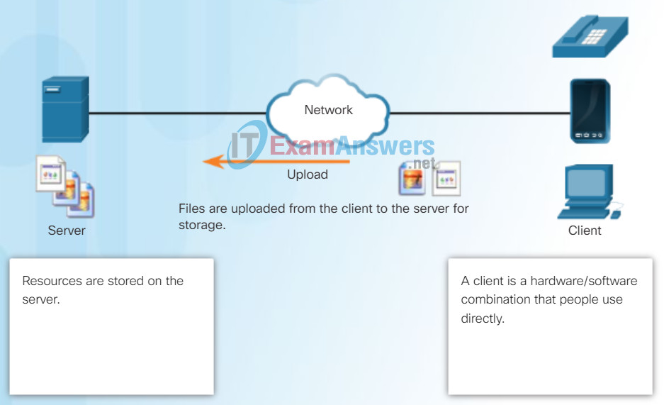
File Server and Client Upload Example
10.1.2.2 The Startup Wizard
In the peer-to-peer (P2P) networking model, the data is accessed from a peer device without the use of a dedicated server.
The P2P network model involves two parts: P2P networks and P2P applications. Both parts have similar features, but in practice work quite differently.
In a P2P network, two or more computers are connected via a network and can share resources (such as printers and files) without having a dedicated server. Every connected end device (known as a peer) can function as both a server and a client. One computer might assume the role of server for one transaction while simultaneously serving as a client for another. The roles of client and server are set on a per request basis.
A simple example of P2P networking is shown in the figure. In addition to sharing files, a network such as this one would allow users to enable networked games, or share an Internet connection.
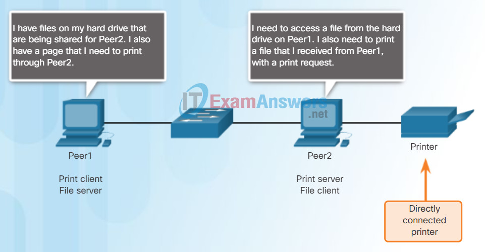
Peer-to-Peer Networking
In a peer-to-peer exchange, both devices are considered equal in the communication process.
10.1.2.3 Different Types of VPN Wizards
A P2P application allows a device to act as both a client and a server within the same communication, as shown in the figure. In this model, every client is a server and every server a client. P2P applications require that each end device provide a user interface and run a background service.
Some P2P applications use a hybrid system where resource sharing is decentralized, but the indexes that point to resource locations are stored in a centralized directory. In a hybrid system, each peer accesses an index server to get the location of a resource stored on another peer.
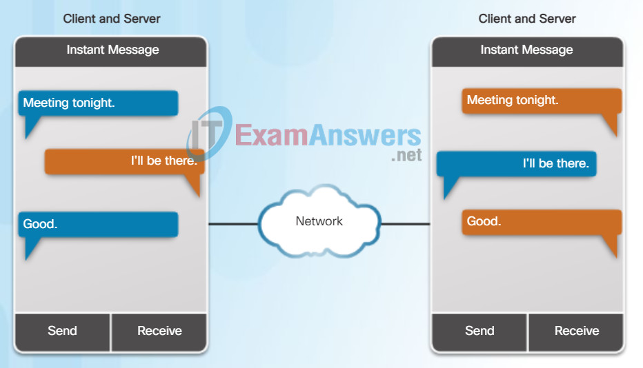
Peer-to-Peer Applications
Both clients simultaneously
- Initiate a message
- Receive a message
10.1.2.4 Other Wizards
With P2P applications, each computer in the network running the application can act as a client or a server for the other computers in the network running the application. Common P2P networks include:
- eDonkey
- G2
- BitTorrent
- Bitcoin
Some P2P applications are based on the Gnutella protocol, where each user shares whole files with other users. As shown in the figure, Gnutella-compatible client software allows users to connect to Gnutella services over the Internet and to locate and access resources shared by other Gnutella peers. Many Gnutella client applications are available, including gtk-gnutella, WireShare, Shareaza, and Bearshare.
Many P2P applications allow users to share pieces of many files with each other at the same time. Clients use a small file called a torrent file to locate other users who have pieces that they need so that they can connect directly to them. This file also contains information about tracker computers that keep track of which users have what files. Clients ask for pieces from multiple users at the same time, known as a swarm. This technology is called BitTorrent. There are many BitTorrent clients including BitTorrent, uTorrent, Frostwire, and qBittorrent.
Note: Any type of file can be shared between users. Many of these files are copyrighted, meaning that only the creator has the right to use and distribute them. It is against the law to download or distribute copyrighted files without permission from the copyright holder. Copyright violation can result in criminal charges and civil lawsuits. Complete the lab on the following page to find out more about these legal issues.
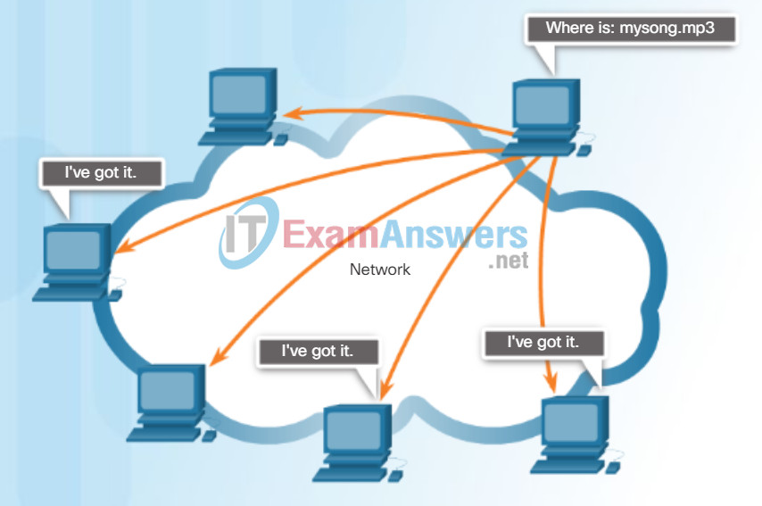
Gnutella Supports P2P Applications
Gnutella allows P2P applications to search for shared resources on peers.
10.1.2.5 Activity – Identify ASDM Wizards
Lab – Researching Peer-to-Peer File Sharing
In this lab, you will complete the following objectives:
- Part 1: Identify P2P Networks, File Sharing Protocols, and Applications
- Part 2: Research P2P File Sharing Issues
- Part 3: Research P2P Copyright Litigations
10.1.3 Configuring Management Settings and Services
10.1.3.1 Configuring Settings in ASDM
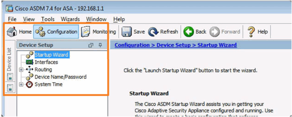
Configuration Device Setup Tab
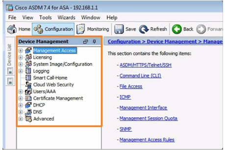
Configuration Device Management Tab
10.1.3.2 Configuring Basic Settings in ASDM
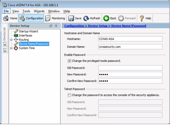
Configuring Hostname, Domain Name, and Enable Password
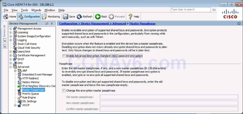
Configuring a Master Passphrase
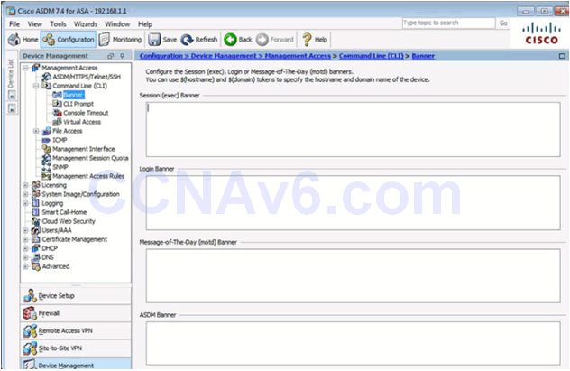
Configuring Legal Notification
10.1.3.3 Configuring Interfaces in ASDM
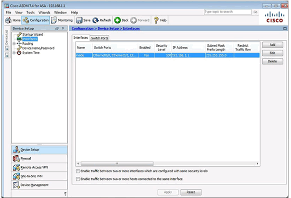
Configuring Interfaces
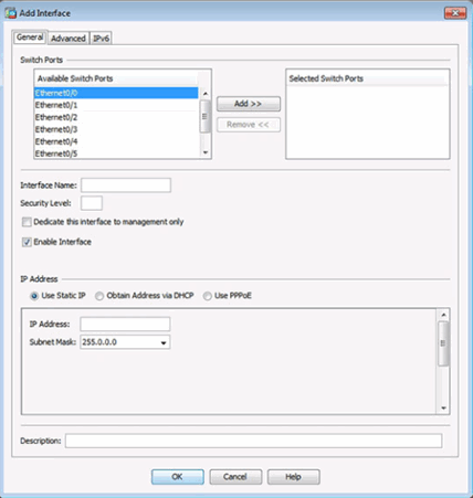
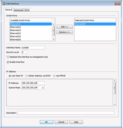
Adding an Outside Interface
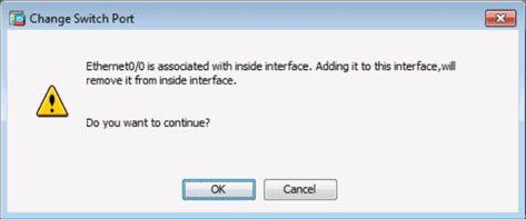
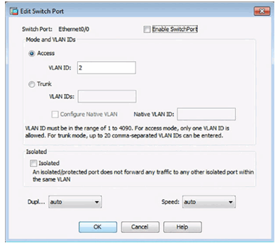
Change Switch Port Window
Adding an Outside Interface
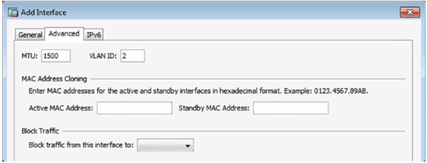
Advanced Outside Interface Settings
Updated Interface Page

Verifying Interfaces
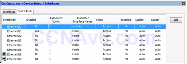
Enable Switch Ports
Apply Configuration

10.1.3.4 Configuring the System Time in ASDM
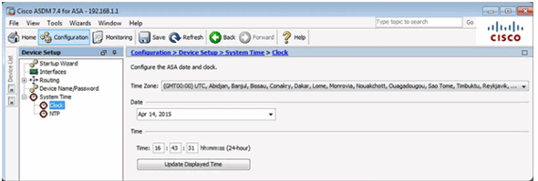
Manually Change the System Time
Use NTP to Change the System Time
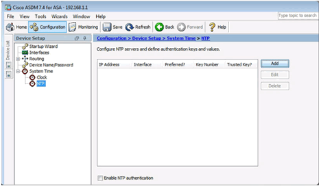
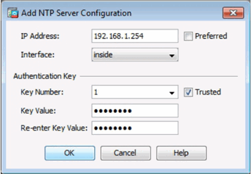
Add an NTP Server
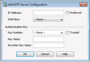
Configure an NTP Server
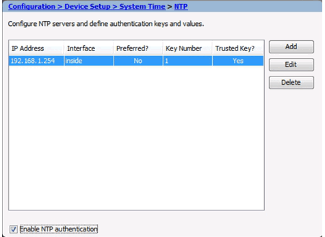
Apply the Configuration
10.1.3.5 Configuring Routing in ASDM
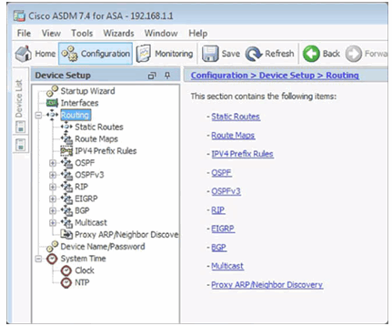
Configuring Routing
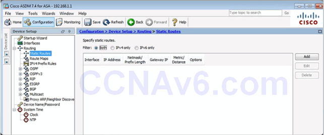
Configuring a Default Static Route
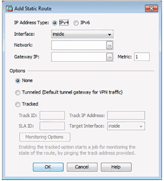
Add or Edit Route Window
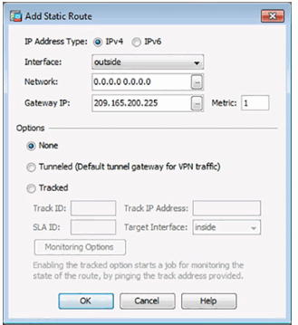
Add Static Route Details
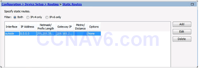
Apply the Configuration
10.1.3.6 Configuring Device Management Access in ASDM
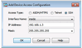
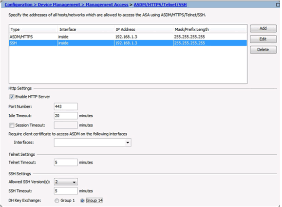
Configure ASDM/HTTPS/Telnet/SSH Access
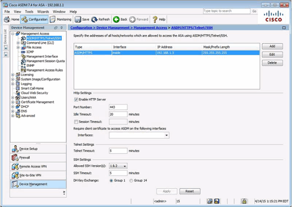
Add Device Access Configuration Window
Configure SSH Settings
10.1.3.7 Configuring DHCP Services in ASDM
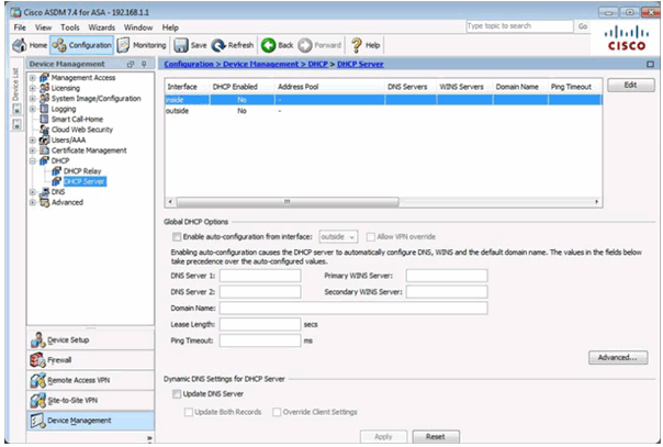
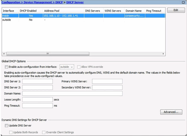
DHCP Server Page
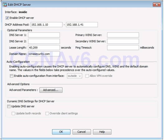
Edit DHCP Server Window
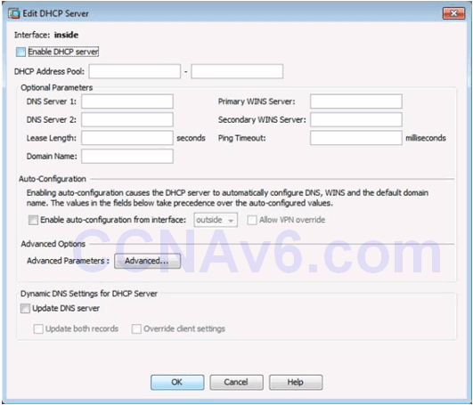
Configuring DHCP Server Services
Verifying DHCP Server Services
10.1.4 Configuring Advanced ASDM Features
10.1.4.1 Objects in ASDM
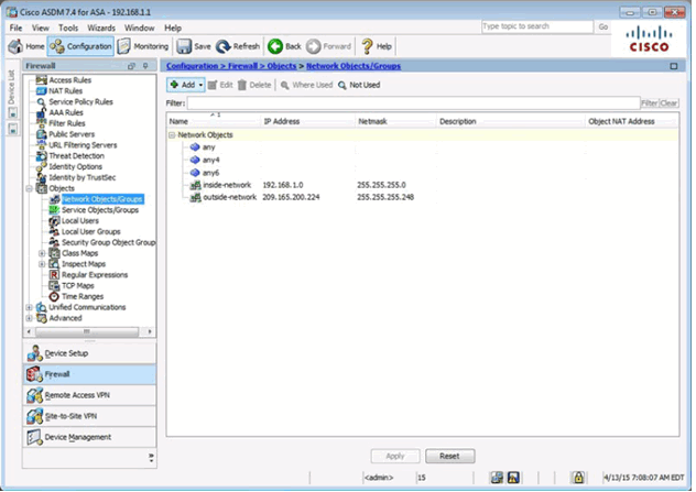
Network Objects/Groups Page
Adding a Network Object/Group
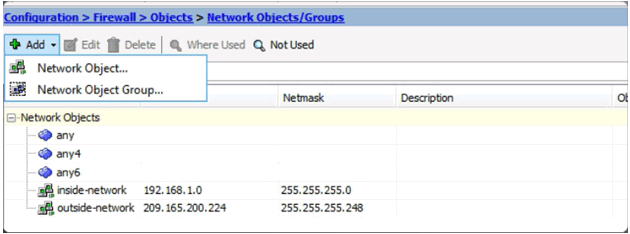
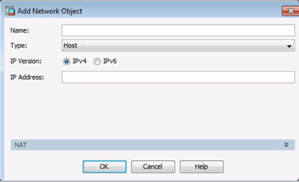
Add Network Object Window
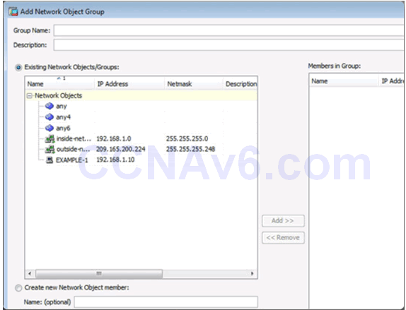
Add Network Object Group Window
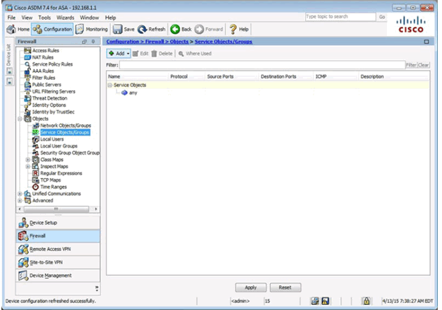
Service Objects/Group Page
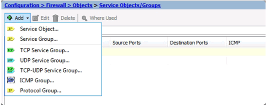
Adding a Service Object/Group
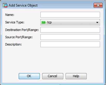
Add Service Object Window
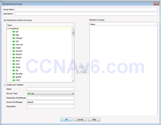
Add Service Object Group Window
10.1.4.2 Configuring ACLs Using ASDM
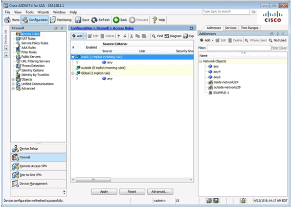
ACLs in ASDM
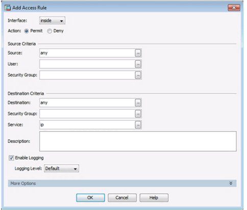
Add Access Rule Window
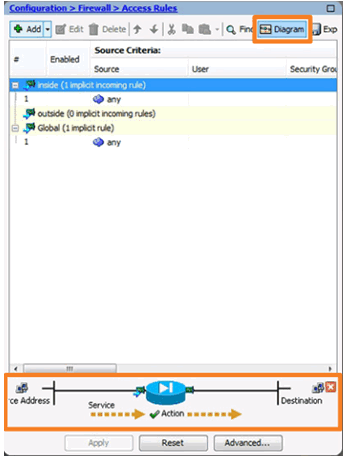
Diagramming Access Rules
10.1.4.3 Configuring Dynamic NAT in ASDM
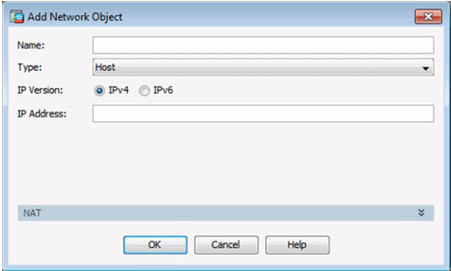
Add Network Object Window
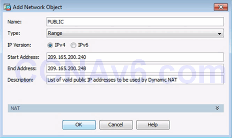
Creating a Network Object for Public Addresses
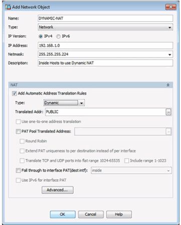
Creating a Network Object for Dynamic NAT
10.1.4.4 Configuring Dynamic PAT in ASDM
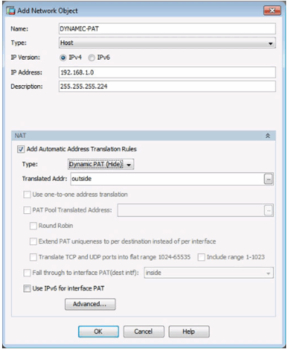
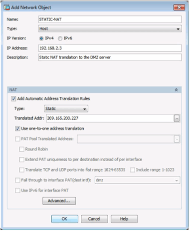
10.1.4.5 Configuring Static NAT in ASDM
Static NAT in ASDM
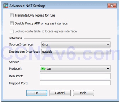
Advanced Static NAT Settings in ASDM
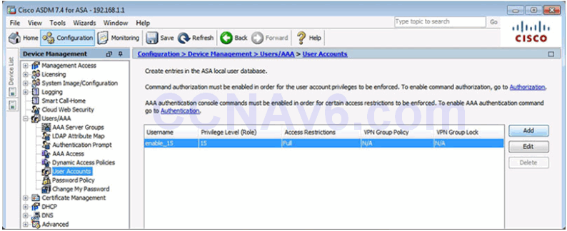
10.1.4.6 Configuring AAA Authentication
User Accounts Page
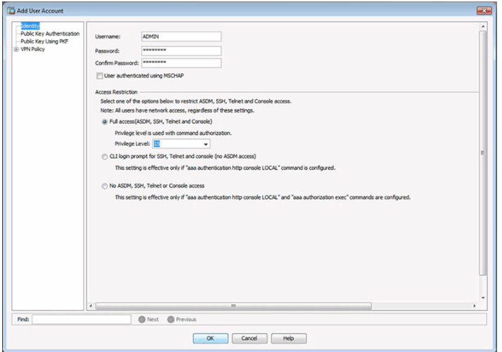
Add User Account Window
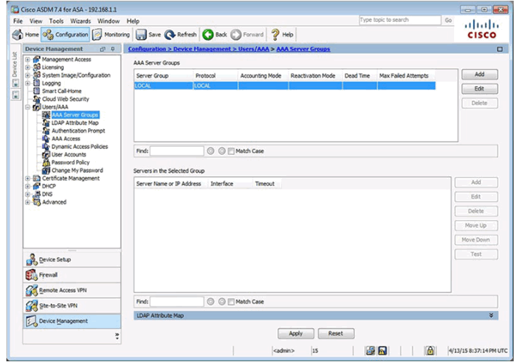
AAA Server Groups Page
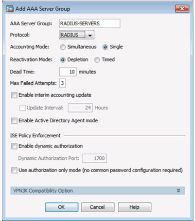
Add AAA Server Group Window
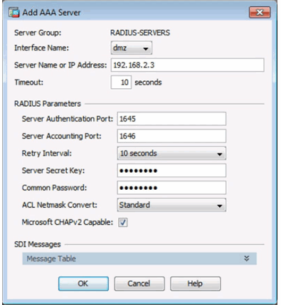
Add AAA Server Window
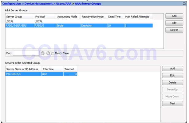
Completed AAA Server Groups Window
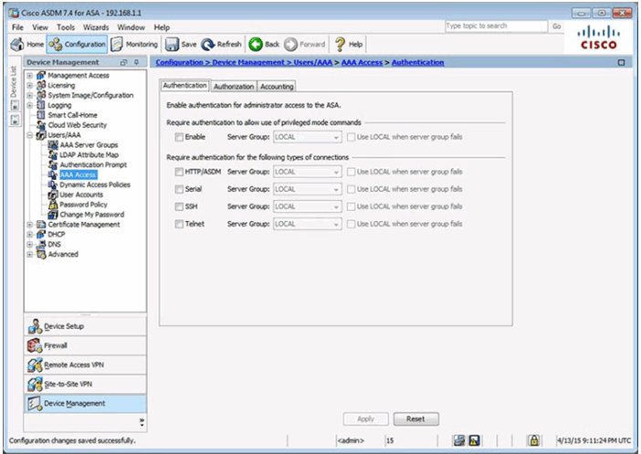
AAA Access Page
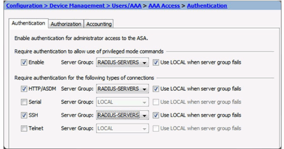
AAA Access > Authentication Window
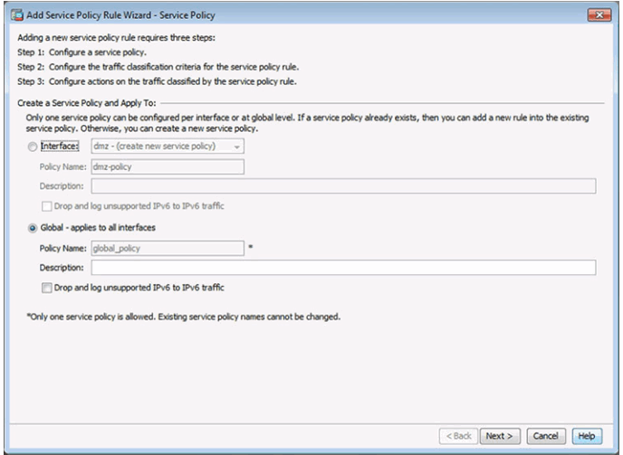
10.1.4.7 Configuring a Service Policy Using ASDM
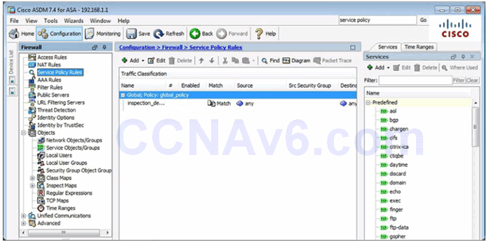
Service Policy in ASDM
Configure a Service Policy
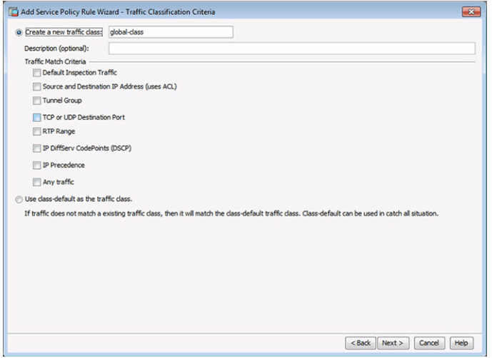
Configure Traffic Classification Criteria
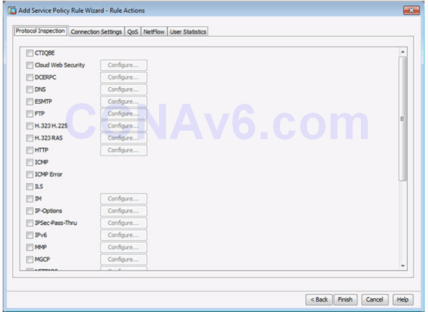
Configure Actions
10.1.4.8 Lab – Configure ASA Basic Settings and Firewall Using ASDM
10.1.4.8 Lab – Configure ASA 5505 Basic Settings and Firewall Using ASDM
10.1.4.8 Lab – Configure ASA 5506-X Basic Settings and Firewall Using ASDM
10.2 ASA VPN Configuration
10.2.1 Site-to-Site VPNs
10.2.1.1 ASA Support for Site-to-Site VPNs
When a web address or uniform resource locator (URL) is typed into a web browser, the web browser establishes a connection to the web service running on the server using the HTTP protocol. URLs and Uniform Resource Identifier (URIs) are the names most people associate with web addresses.
To better understand how the web browser and web server interact, we can examine how a web page is opened in a browser. For this example, use the http://www.cisco.com/index.html URL.
First, as shown in Figure 1, the browser interprets the three parts of the URL:
1. http (the protocol or scheme)
2. www.cisco.com (the server name)
3. index.html (the specific filename requested)
As shown in Figure 2, the browser then checks with a name server to convert www.cisco.com into a numeric IP address, which it uses to connect to the server. Using HTTP requirements, the browser sends a GET request to the server and asks for the index.html file. The server, as shown in Figure 3, sends the HTML code for this web page to the browser. Finally, as shown in Figure 4, the browser deciphers the HTML code and formats the page for the browser window.

HTTP Protocol Step 1
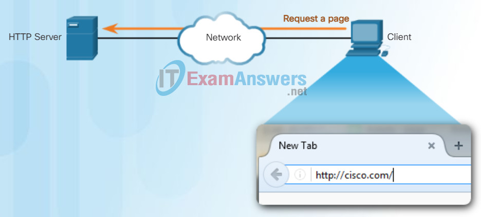
The client initiates an HTTP request to a server.
HTTP Protocol Step 2
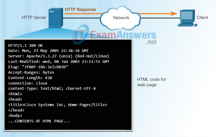
In response to the request, the HTTP server returns code for a web page.
HTTP Protocol Step 3
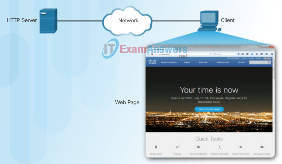
The browser interprets the HTML code and displays a web page.
10.2.1.2 ASA Site-to-Site VPNs Using ASDM
HTTP is a request/response protocol. When a client, typically a web browser, sends a request to a web server, HTTP specifies the message types used for that communication. The three common message types are GET, POST, and PUT (see the figure):
- GET – A client request for data. A client (web browser) sends the GET message to the web server to request HTML pages.
- POST – Uploads data files to the web server such as form data.
- PUT – Uploads resources or content to the web server such as an image.
Although HTTP is remarkably flexible, it is not a secure protocol. The request messages send information to the server in plain text that can be intercepted and read. The server responses, typically HTML pages, are also unencrypted.
For secure communication across the Internet, the HTTP Secure (HTTPS) protocol is used. HTTPS uses authentication and encryption to secure data as it travels between the client and server. HTTPS uses the same client request-server response process as HTTP, but the data stream is encrypted with Secure Socket Layer (SSL) before being transported across the network.
HTTP Protocol using GET
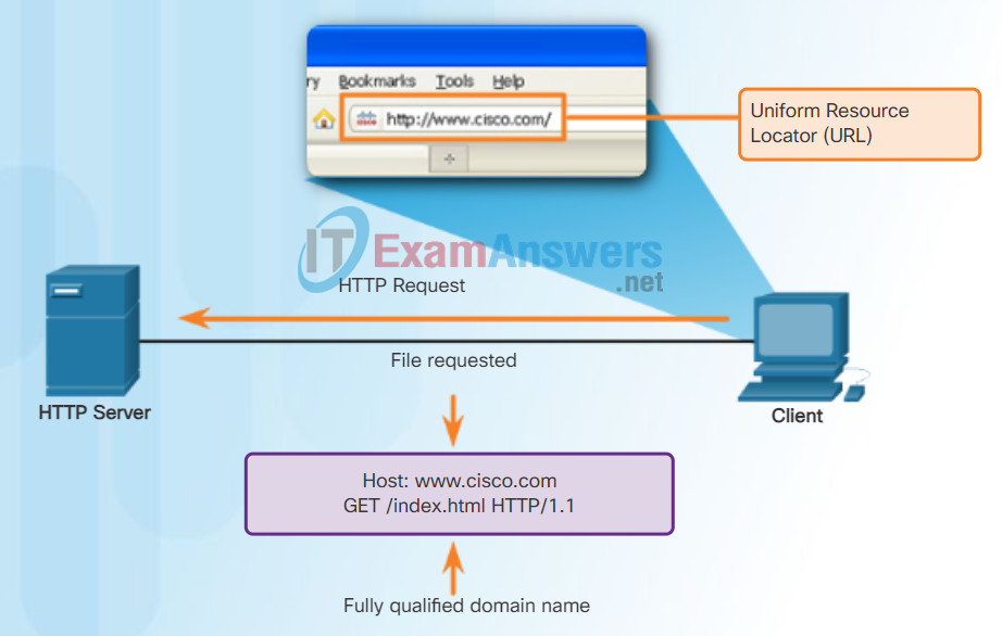
Entering ‘http://www.cisco.com’ in the address bar of a web browser generates the HTTP ‘GET’ message.
10.2.1.3 Configuring the ISR Site-to-Site VPNs Using the CLI
Email Protocols
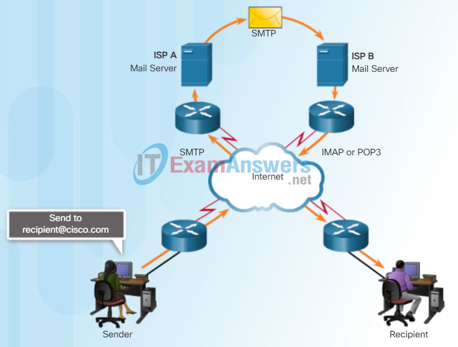
One of the primary services offered by an ISP is email hosting. To run on a computer or other end device, email requires several applications and services, as shown in the figure. Email is a store-and-forward method of sending, storing, and retrieving electronic messages across a network. Email messages are stored in databases on mail servers.
Email clients communicate with mail servers to send and receive email. Mail servers communicate with other mail servers to transport messages from one domain to another. An email client does not communicate directly with another email client when sending email. Instead, both clients rely on the mail server to transport messages.
Email supports three separate protocols for operation: Simple Mail Transfer Protocol (SMTP), Post Office Protocol (POP), and IMAP. The application layer process that sends mail uses SMTP. A client retrieves email, however, using one of the two application layer protocols: POP or IMAP.
10.2.1.4 Configuring the ASA Site-to-Site VPNs Using ASDM
SMTP Operation
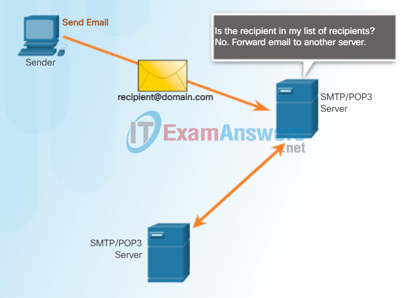
SMTP message formats require a message header and a message body. While the message body can contain any amount of text, the message header must have a properly formatted recipient email address and a sender address.
When a client sends email, the client SMTP process connects with a server SMTP process on well-known port 25. After the connection is made, the client attempts to send the email to the server across the connection. When the server receives the message, it either places the message in a local account, if the recipient is local, or forwards the message to another mail server for delivery, as shown in the figure.
The destination email server may not be online or may be busy when email messages are sent. Therefore, SMTP spools messages to be sent at a later time. Periodically, the server checks the queue for messages and attempts to send them again. If the message is still not delivered after a predetermined expiration time, it is returned to the sender as undeliverable.
10.2.1.5 Configuring the ASA Site-to-Site VPNs Using ASDM (Cont.)
POP Operation
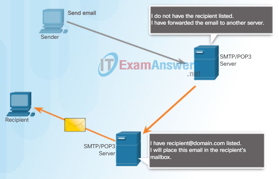
POP3
POP is used by an application to retrieve mail from a mail server. With POP, mail is downloaded from the server to the client and then deleted on the server. This is how POP operates, by default.
The server starts the POP service by passively listening on TCP port 110 for client connection requests. When a client wants to make use of the service, it sends a request to establish a TCP connection with the server. When the connection is established, the POP server sends a greeting. The client and POP server then exchange commands and responses until the connection is closed or aborted.
With POP, email messages are downloaded to the client and removed from the server, so there is no centralized location where email messages are kept. Because POP does not store messages, it is undesirable for a small business that needs a centralized backup solution.
10.2.1.6 Configuring the ASA Site-to-Site VPNs Using ASDM (Cont.)
IMAP Operation
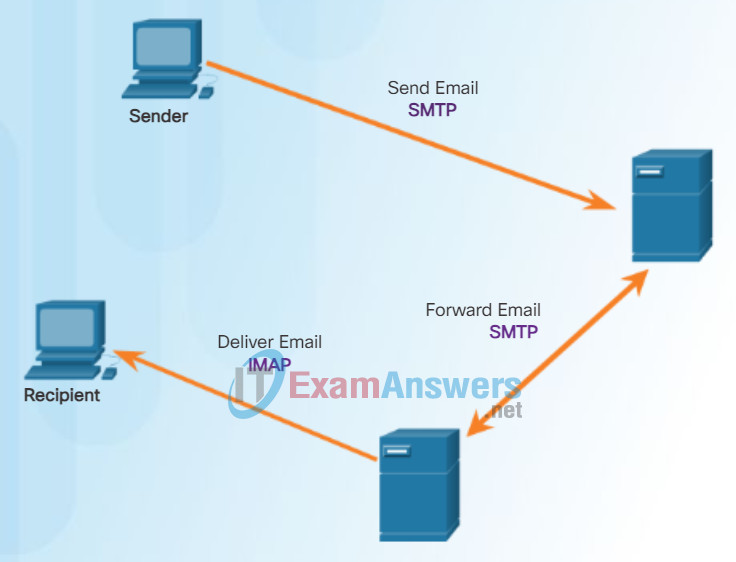
IMAP is another protocol that describes a method to retrieve email messages. Unlike POP, when the user connects to an IMAP-capable server, copies of the messages are downloaded to the client application. The original messages are kept on the server until manually deleted. Users view copies of the messages in their email client software.
Users can create a file hierarchy on the server to organize and store mail. That file structure is duplicated on the email client as well. When a user decides to delete a message, the server synchronizes that action and deletes the message from the server.
Click here to learn more about email protocols.
10.2.1.7 Verifying Site-to-Site VPNs Using ASDM
Packet Tracer – Web and Email
In this activity, you will configure HTTP and email services using the simulated server in Packet Tracer. You will then configure clients to access the HTTP and email services.
10.2.1.8 Test the Site-to-Site VPN Using ASDM
10.2.1.9 Lab – Configure a Site-to-Site IPsec VPN Using ISR CLI and ASA ASDM
10.2.1.9 Lab – Configure a Site-to-Site IPsec VPN Using ISR CLI and ASA 5505 ASDM
10.2.1.9 Lab – Configure a Site-to-Site IPsec VPN Using ISR CLI and ASA 5506-X ASDM
10.2.2 Remote-Access VPNs
10.2.2.1 Remote-Access VPN Options
Domain Name Service
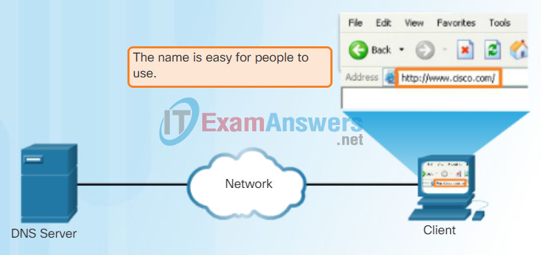
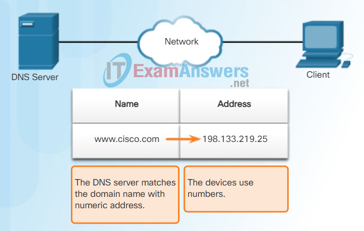
In data networks, devices are labeled with numeric IP addresses to send and receive data over networks. Domain names were created to convert the numeric address into a simple, recognizable name.
On the Internet, these domain names, such as http://www.cisco.com, are much easier for people to remember than 198.133.219.25, which is the actual numeric address for this server. If Cisco decides to change the numeric address of www.cisco.com, it is transparent to the user because the domain name remains the same. The new address is simply linked to the existing domain name and connectivity is maintained.
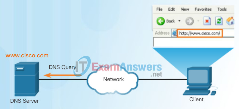
The DNS protocol defines an automated service that matches resource names with the required numeric network address. It includes the format for queries, responses, and data. The DNS protocol communications use a single format called a message. This message format is used for all types of client queries and server responses, error messages, and the transfer of resource record information between servers.
Figures 1 through 5 display the steps involved in DNS resolution.
Resolving DNS Addresses Step 1
Resolving DNS Addresses Step 2
Resolving DNS Addresses Step 3
Resolving DNS Addresses Step 4
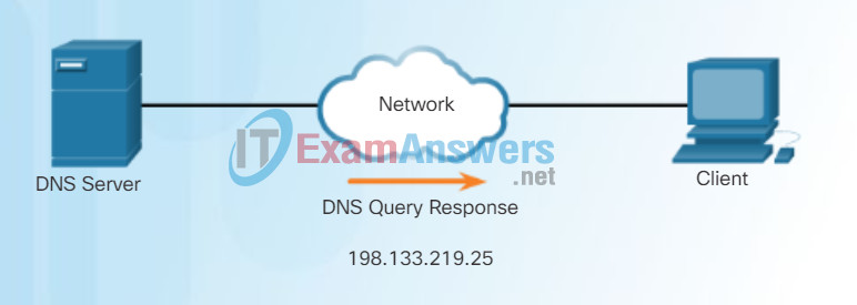
The number is returned back to the client for use in making requests of the server.
Resolving DNS Addresses Step 5

A domain name is resolved to its numeric network device address by the DNS protocol.
10.2.2.2 IPsec versus SSL
The DNS server stores different types of resource records used to resolve names. These records contain the name, address, and type of record. Some of these record types are:
- A – An end device IPv4 address
- NS – An authoritative name server
- AAAA – An end device IPv6 address (pronounced quad-A)
- MX – A mail exchange record
When a client makes a query, the server’s DNS process first looks at its own records to resolve the name. If it is unable to resolve the name using its stored records, it contacts other servers to resolve the name. After a match is found and returned to the original requesting server, the server temporarily stores the numbered address in the event that the same name is requested again.
The DNS Client service on Windows PCs also stores previously resolved names in memory. The ipconfig /displaydns command displays all of the cached DNS entries.
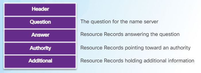
DNS uses the same message format for:
- all types of client queries and server responses
- error messages
- the transfer of resource record information between servers
10.2.2.3 ASA SSL VPNs
DNS Hierarchy
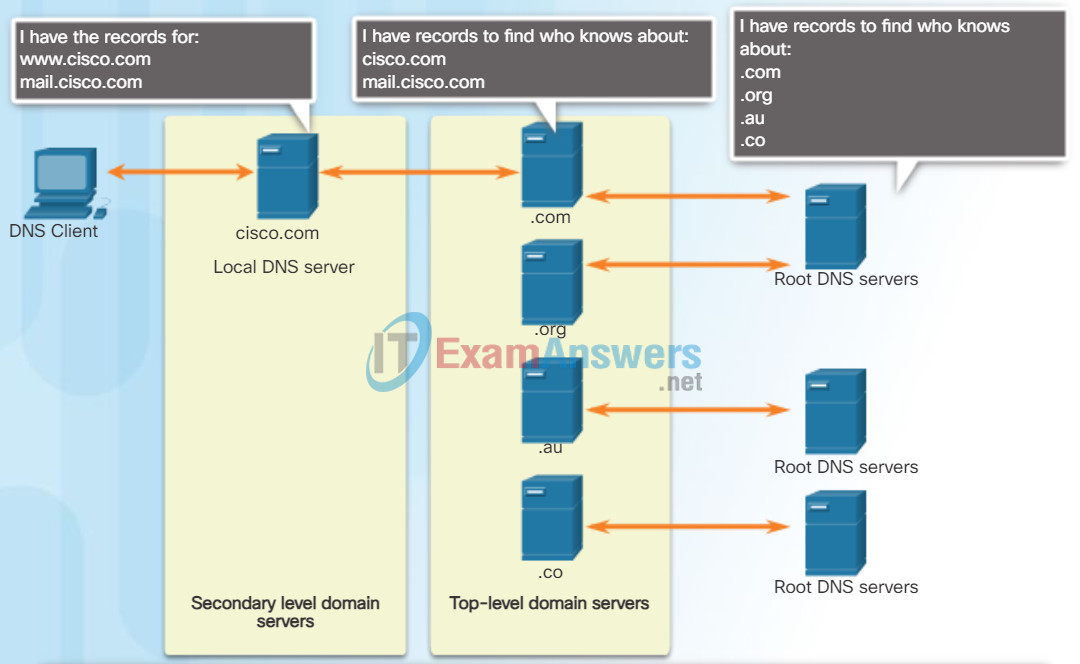
A hierarchy of DNS servers contains the resource records that match names with addresses.
The DNS protocol uses a hierarchical system to create a database to provide name resolution. The hierarchy looks like an inverted tree with the root at the top and branches below (see the figure). DNS uses domain names to form the hierarchy.
The naming structure is broken down into small, manageable zones. Each DNS server maintains a specific database file and is only responsible for managing name-to-IP mappings for that small portion of the entire DNS structure. When a DNS server receives a request for a name translation that is not within its DNS zone, the DNS server forwards the request to another DNS server within the proper zone for translation.
Note: DNS is scalable because hostname resolution is spread across multiple servers.
The different top-level domains represent either the type of organization or the country of origin. Examples of top-level domains are:
- .com – a business or industry
- .org – a non-profit organization
- .au – Australia
- .co – Colombia
10.2.2.4 Clientless SSL VPN Solution
When configuring a network device, one or more DNS Server addresses are provided that the DNS client can use for name resolution. Usually the Internet service provider (ISP) provides the addresses to use for the DNS servers. When a user’s application requests to connect to a remote device by name, the requesting DNS client queries the name server to resolve the name to a numeric address.
Computer operating systems also have a utility called nslookup that allows the user to manually query the name servers to resolve a given host name. This utility can also be used to troubleshoot name resolution issues and to verify the current status of the name servers.
In Figure 1, when the nslookup command is issued, the default DNS server configured for your host is displayed. The name of a host or domain can be entered at the nslookup prompt. The nslookup utility has many options available for extensive testing and verification of the DNS process.
In Figure 2, use the Syntax Checker activity to practice entering the nslookup command in both Windows and Linux.
Using nslookup
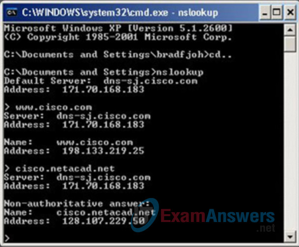
DNS CLI Commands in Windows and Linux
From the Windows command prompt, enter the 'nslookup' command to begin
a manual query of the name servers.

c:\> nslookup
Default Server:  UnKnown
Address:  10.10.10.1

The output lists the name and IP address of the DNS server configured in the client.
Note that the DNS server address can be manually configured or dynamically learned through
DHCP. You are now in nslookup mode. Enter the domain name ‘www.cisco.com’.

> www.cisco.com
Server:  e144.dscb.akamaiedge.net
Addresses:  2600:1400:1:1:8500::90
          2600:1400:1:1:8200::90
          2600:1400:1:1:8100::90
          23.67.208.170
Aliases:  www.cisco.com
          www.cisco.com.akadns.net
          wwwds.cisco.com.edgekey.net
          wwwds.cisco.com.edgekey.net.globalredir.akadns.net

The output lists the ‘www.cisco.com’ related IP addresses that the server ‘e144’ currently
has in its database. Notice that IPv6 addresses are also listed. In addition, various aliases
are shown that will resolve to ‘www.cisco.com’. Enter the ‘exit’ command to leave nslookup mode
and return to the Windows command line.

> exit
C:\>
You can directly query the DNS servers by simply adding the domain name to the 'nslookup' command.
Enter 'nslookup www.google.com'.
c:\> nslookup www.google.com
Server:  UnKnown
Address:  10.10.10.1

Non-authoritative answer:
Name:    www.google.com
Addresses:  2001:4860:4002:802::1014
          74.125.227.80
          74.125.227.84
          74.125.227.83
          74.125.227.82
          74.125.227.81

You are now working from Linux command prompt. The nslookup command is the same.
Enter the 'nslookup' command to begin a manual query of the name servers.
Enter 'www.cisco.com' at the > prompt.
Enter 'exit' to leave nslookup mode and return to the Linux command line.

user@cisconetacad$ nslookup
Server:        127.0.1.1
Address:    127.0.1.1#53
> www.cisco.com
Non-authoritative answer:
www.cisco.com    canonical name = www.cisco.com.akadns.net.
www.cisco.com.akadns.net    canonical name = wwwds.cisco.com.edgekey.net.
wwwds.cisco.com.edgekey.net    canonical name = wwwds.cisco.com.edgekey.net.globalredir.akadns.net.
wwwds.cisco.com.edgekey.net.globalredir.akadns.net    canonical name = e144.dscb.akamaiedge.net.
Name:    e144.dscb.akamaiedge.net
Address: 23.60.112.170
> exit
user@cisconetacad$

As in Windows, you can directly query the DNS servers by simply adding the domain name
to the nslookup command. Enter 'nslookup www.google.com'.

user@cisconetacad$# nslookup www.google.com
Server:        127.0.1.1
Address:    127.0.1.1#53

Non-authoritative answer:
Name:    www.google.com
Address: 74.125.225.209
Name:    www.google.com
Address: 74.125.225.210
Name:    www.google.com
Address: 74.125.225.211
Name:    www.google.com
Address: 74.125.225.212
Name:    www.google.com
Address: 74.125.225.208

user@cisconetacad$
You successfully used the nslookup command to verify the status of domain names.
10.2.2.5 Client-Based SSL VPN Solution
Dynamic Host Configuration Protocol
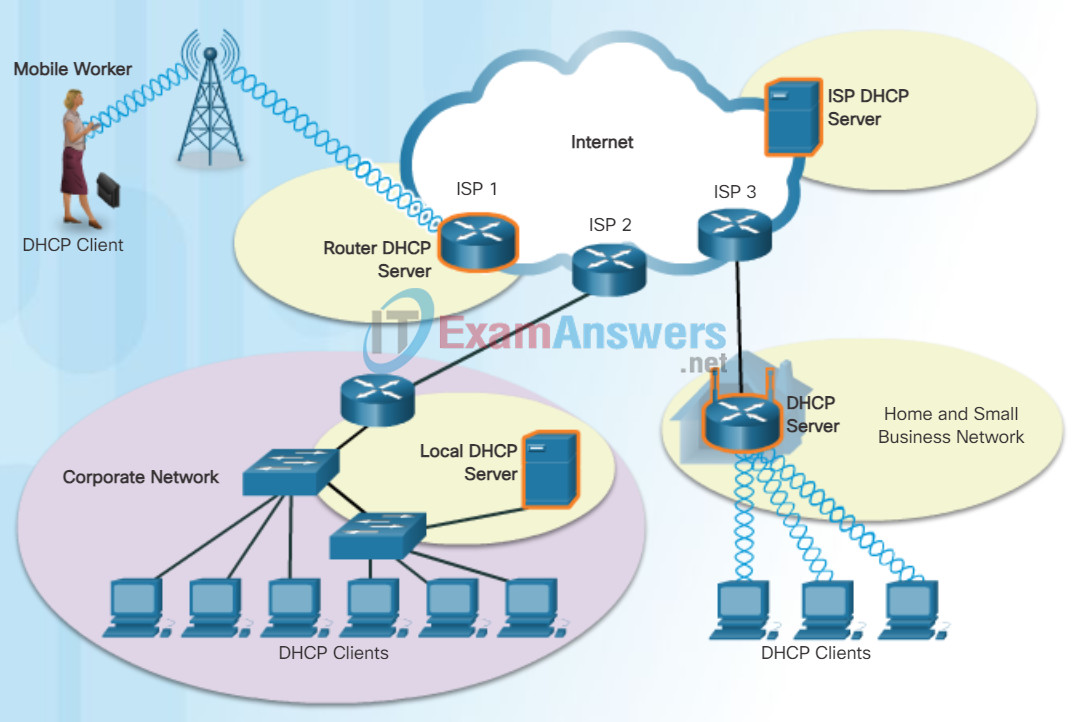
The Dynamic Host Configuration Protocol (DHCP) for IPv4 service automates the assignment of IPv4 addresses, subnet masks, gateways, and other IPv4 networking parameters. This is referred to as dynamic addressing. The alternative to dynamic addressing is static addressing. When using static addressing, the network administrator manually enters IP address information on hosts.
When a host connects to the network, the DHCP server is contacted, and an address is requested. The DHCP server chooses an address from a configured range of addresses called a pool and assigns (leases) it to the host.
On larger networks, or where the user population changes frequently, DHCP is preferred for address assignment. New users may arrive and need connections; others may have new computers that must be connected. Rather than use static addressing for each connection, it is more efficient to have IPv4 addresses assigned automatically using DHCP.
DHCP-distributed addresses are leased for a set period of time. When the lease is expired, the address is returned to the pool for reuse if the host has been powered down or taken off the network. Users can freely move from location to location and easily re-establish network connections through DHCP.
As the figure shows, various types of devices can be DHCP servers. The DHCP server in most medium-to-large networks is usually a local, dedicated PC-based server. With home networks, the DHCP server is usually located on the local router that connects the home network to the ISP.
Many networks use both DHCP and static addressing. DHCP is used for general purpose hosts, such as end user devices. Static addressing is used for network devices, such as gateways, switches, servers, and printers.
DHCPv6 (DHCP for IPv6) provides similar services for IPv6 clients. One important difference is that DHCPv6 does not provide a default gateway address. This can only be obtained dynamically from the router’s Router Advertisement message.
10.2.2.6 Cisco AnyConnect Secure Mobility Client
DHCP Operation
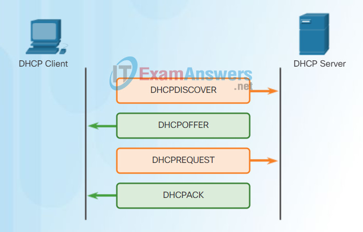
As shown in the figure, when an IPv4, DHCP-configured device boots up or connects to the network, the client broadcasts a DHCP discover (DHCPDISCOVER) message to identify any available DHCP servers on the network. A DHCP server replies with a DHCP offer (DHCPOFFER) message, which offers a lease to the client. The offer message contains the IPv4 address and subnet mask to be assigned, the IPv4 address of the DNS server, and the IPv4 address of the default gateway. The lease offer also includes the duration of the lease.
The client may receive multiple DHCPOFFER messages if there is more than one DHCP server on the local network. Therefore, it must choose between them, and sends a DHCP request (DHCPREQUEST) message that identifies the explicit server and lease offer that the client is accepting. A client may also choose to request an address that it had previously been allocated by the server.
Assuming that the IPv4 address requested by the client, or offered by the server, is still available, the server returns a DHCP acknowledgment (DHCPACK) message that acknowledges to the client that the lease has been finalized. If the offer is no longer valid, then the selected server responds with a DHCP negative acknowledgment (DHCPNAK) message. If a DHCPNAK message is returned, then the selection process must begin again with a new DHCPDISCOVER message being transmitted. After the client has the lease, it must be renewed prior to the lease expiration through another DHCPREQUEST message.
The DHCP server ensures that all IP addresses are unique (the same IP address cannot be assigned to two different network devices simultaneously). Most Internet providers use DHCP to allocate addresses to their customers.
DHCPv6 has similar set of messages to those shown in the figure for DHCP for IPv4. The DHCPv6 messages are SOLICIT, ADVERTISE, INFORMATION REQUEST, and REPLY
10.2.2.7 AnyConnect for Mobile Devices
Packet Tracer – DHCP and DNS Servers
In this activity, you will configure and verify static IP addressing and DHCP addressing. You will then configure a DNS server to map IP addresses to the web site names.
10.2.3 Configuring Clientless SSL VPN
10.2.3.1 Configuring Clientless SSL VPN on an ASA
File Transfer Protocol
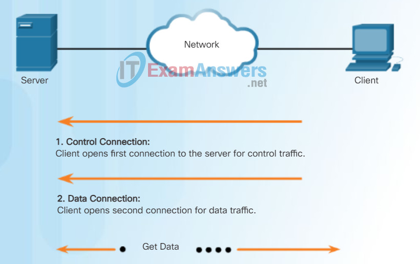
Based on commands sent across control connection, data can be downloaded from server or uploaded from client.
FTP is another commonly used application layer protocol. FTP was developed to allow for data transfers between a client and a server. An FTP client is an application that runs on a computer that is used to push and pull data from an FTP server.
As the figure illustrates, to successfully transfer data, FTP requires two connections between the client and the server, one for commands and replies, the other for the actual file transfer:
- The client establishes the first connection to the server for control traffic using TCP port 21, consisting of client commands and server replies.
- The client establishes the second connection to the server for the actual data transfer using TCP port 20. This connection is created every time there is data to be transferred.
- The data transfer can happen in either direction. The client can download (pull) data from the server, or the client can upload (push) data to the server.
10.2.3.2 Sample Clientless VPN Topology
Server Message Block
The Server Message Block (SMB) is a client/server file sharing protocol that describes the structure of shared network resources, such as directories, files, printers, and serial ports. It is a request-response protocol. All SMB messages share a common format. This format uses a fixed-sized header, followed by a variable-sized parameter and data component.
SMB messages can:
- Start, authenticate, and terminate sessions
- Control file and printer access
- Allow an application to send or receive messages to or from another device
SMB file-sharing and print services have become the mainstay of Microsoft networking. With the introduction of the Windows 2000 software series, Microsoft changed the underlying structure for using SMB. In previous versions of Microsoft products, the SMB services used a non-TCP/IP protocol to implement name resolution. Beginning with Windows2000, all subsequent Microsoft products use DNS naming, which allows TCP/IP protocols to directly support SMB resource sharing, as shown in Figure 1. The SMB file exchange process between Windows PCs is shown in Figure 2.
SMB Protocol
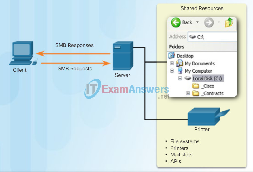
SMB is a client-server, request-response protocol. Servers can make their resources available to clients on the network.
Unlike the file sharing supported by FTP, clients establish a long-term connection to servers. After the connection is established, the user of the client can access the resources on the server as if the resource is local to the client host.
SMB File Sharing
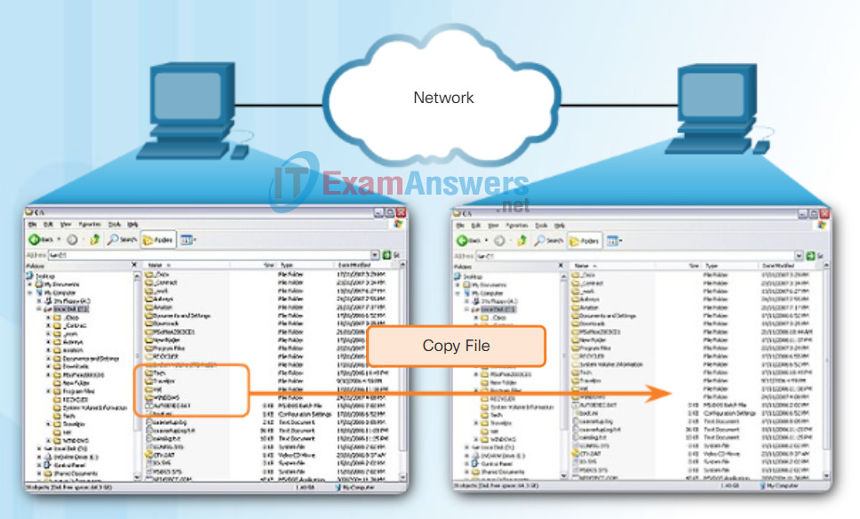
A file may be copied from PC to PC with Windows Explorer using the SMB protocol.
The LINUX and UNIX operating systems also provide a method of sharing resources with Microsoft networks using a version of SMB called SAMBA. The Apple Macintosh operating systems also support resource sharing using the SMB protocol.
10.2.3.3 Clientless SSL VPN
Packet Tracer – FTP
In this activity, you will configure FTP services. You will then use the FTP services to transfer files between clients and the server.
10.2.3.4 Clientless SSL VPN (Cont.)
Lab – Exploring FTP
In this lab, you will complete the following objectives:
- Part 1: Use FTP from a Command Prompt
- Part 2: Download an FTP File Using WS_FTP LE
- Part 3: Use FTP in a Browser
10.2.3.5 Clientless SSL VPN (Cont.)
Clientless SSL VPN Introduction Window
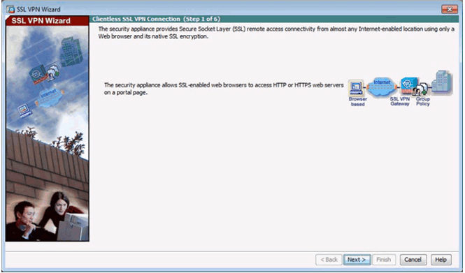
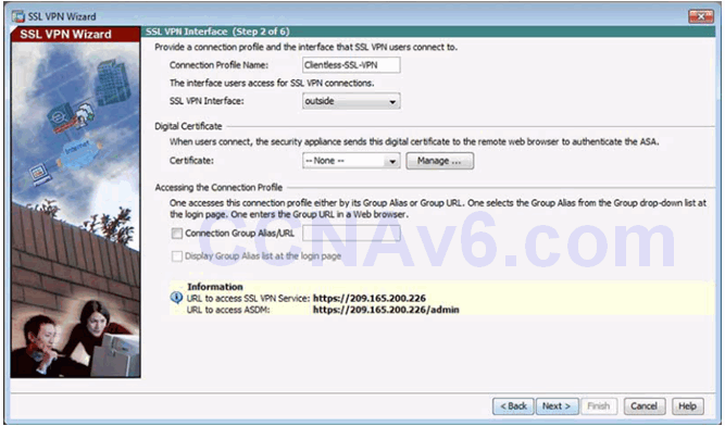
SSL VPN Interface Window
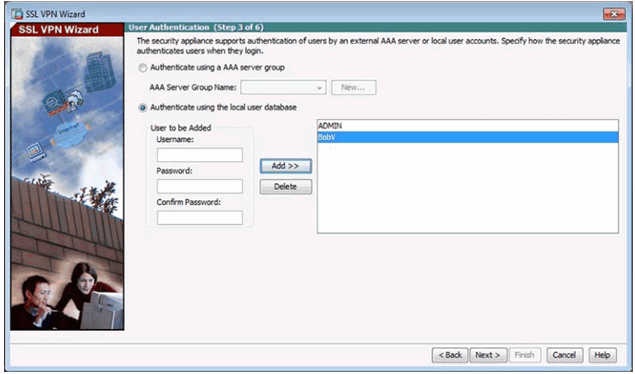
User Authentication Window
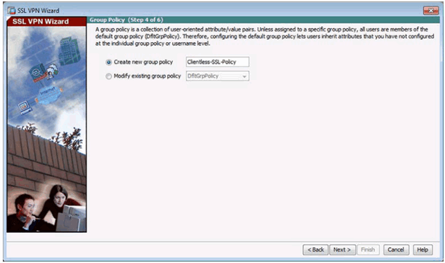
Group Policy Window
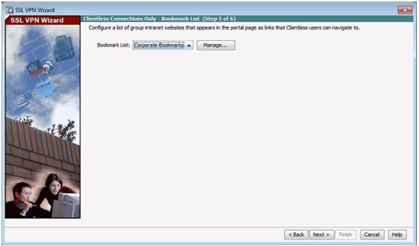
Bookmark List Window
Configure GUI Customization Objects Window
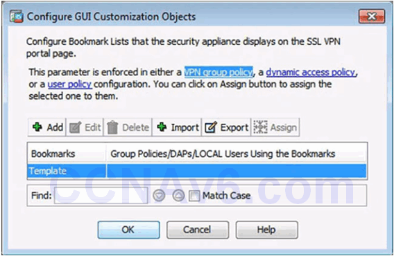
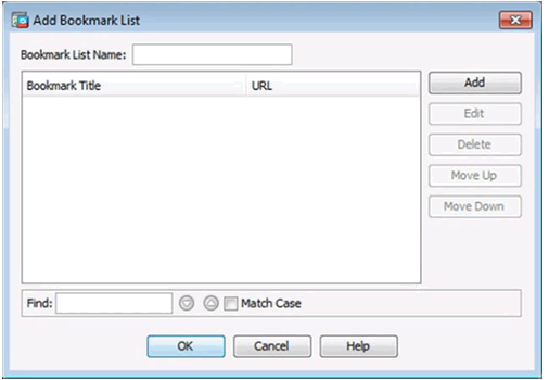
Add Bookmark List Window
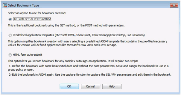
Select Bookmark Type Window
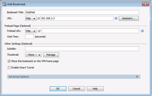
Add Bookmark Window
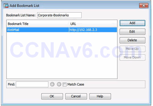
Revised Add Bookmark List Window
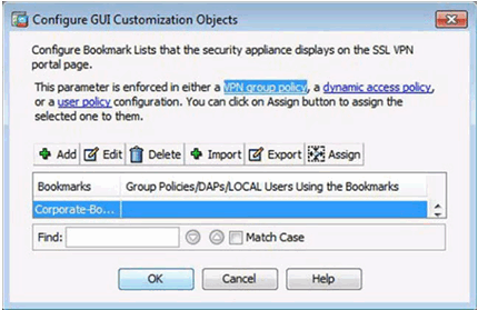
Revised Configure GUI Customization Objects Window
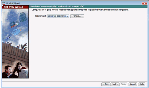
Revised Bookmark List Window
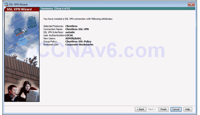
Summary Window
10.2.3.7 Verifying Clientless SSL VPN
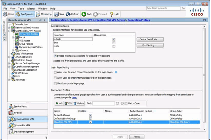
10.2.3.8 Testing the Clientless SSL VPN Connection
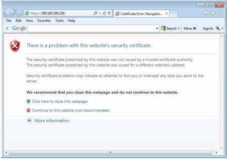
Security Certificate Window
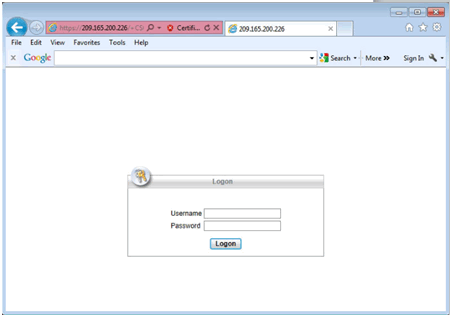
Logon Window
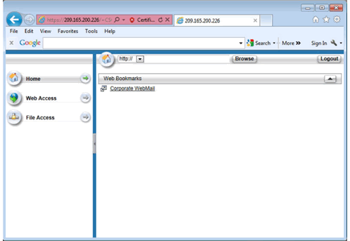
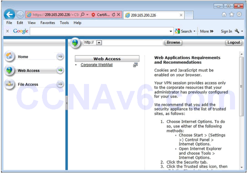
Web Portal Home Page
Web Portal Web Access Page
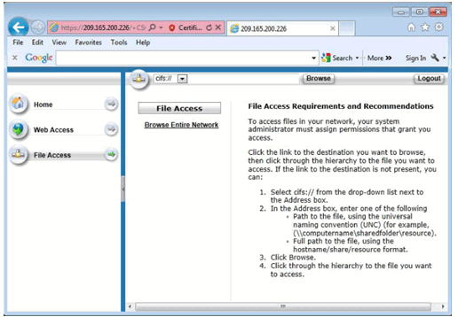
Web Portal File Access Page
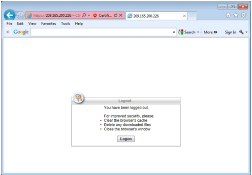
Log Out of the Web Portal
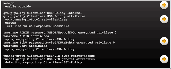
10.2.3.9 Viewing the Generated CLI Config
10.2.4 Configuring AnyConnect SSL VPN
10.2.4.1 Configuring SSL VPN AnyConnect
ASDM Assistant
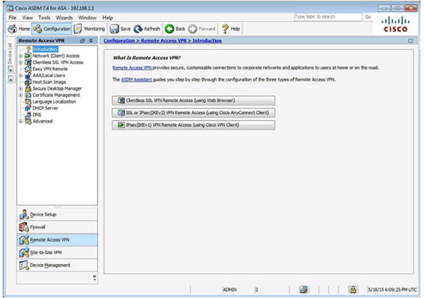
Client-Based VPN Wizard

10.2.4.2 Sample SSL VPN Topology
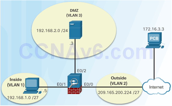
10.2.4.3 AnyConnect SSL VPN
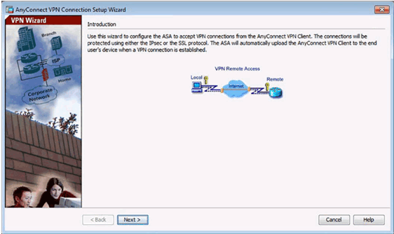
nyConnect VPN Wizard Introduction Window
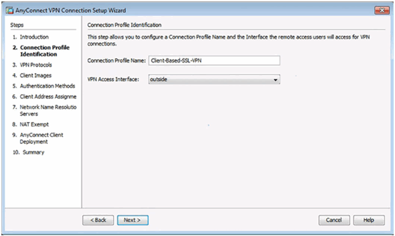
Connection Profile Identification Window
VPN Protocols Window
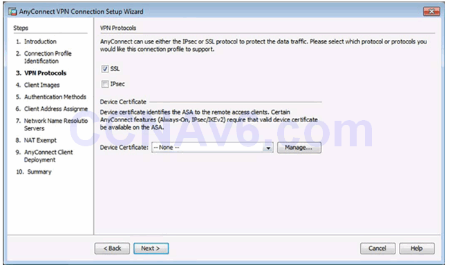
Client Images Window
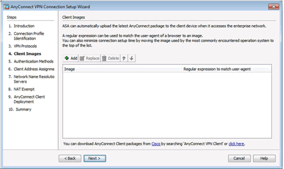
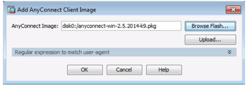
Add AnyConnect Client Image Window
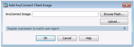
Browse Flash Window
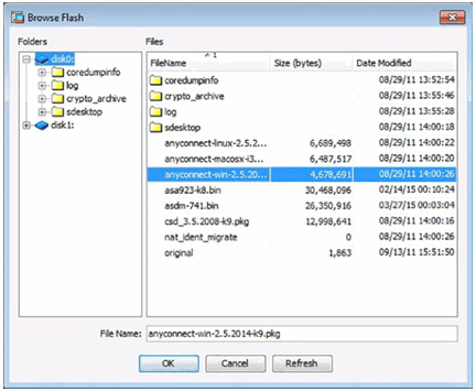
Add AnyConnect Client Image Window
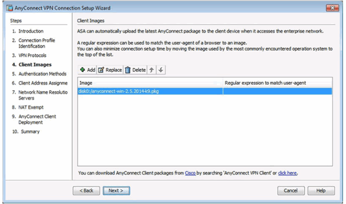
Completed Client Images Window
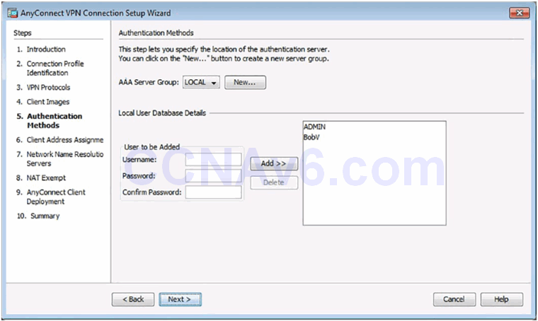
Authentication Methods Window
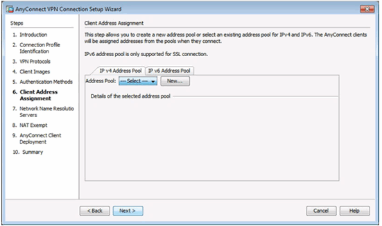
Client Address Management Window
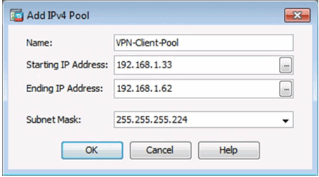
Add IPv4 Window
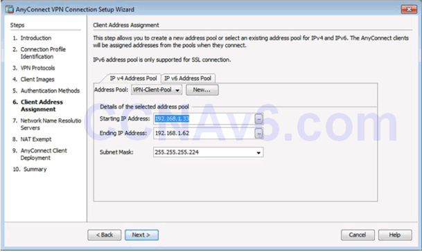
Completed Client Address Management Window
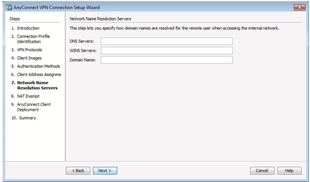
Network Name Resolution Servers Window
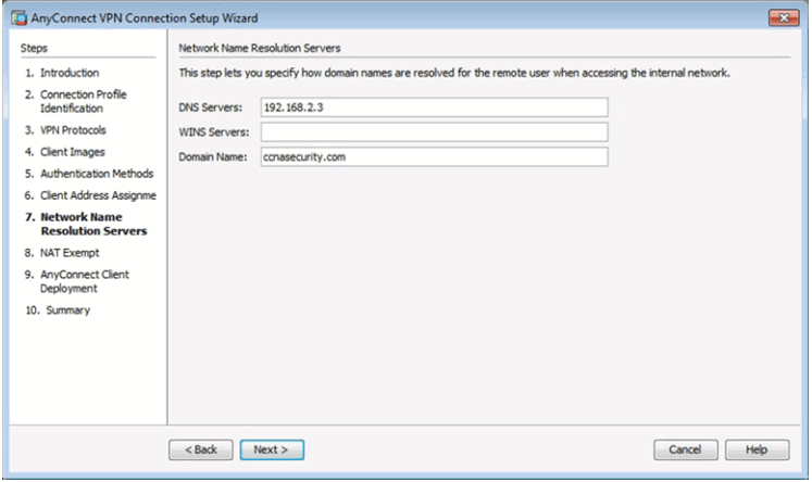
Completed Network Name Resolution Servers Window
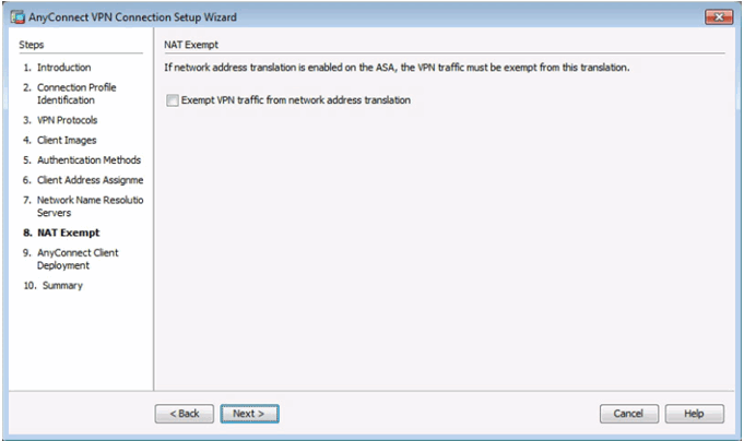
NAT Exempt Window
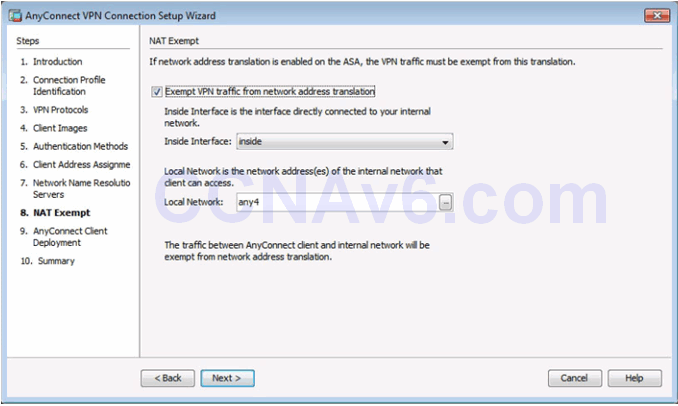
Completed NAT Exempt Window
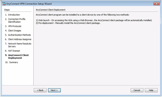
AnyConnect Client Deployment
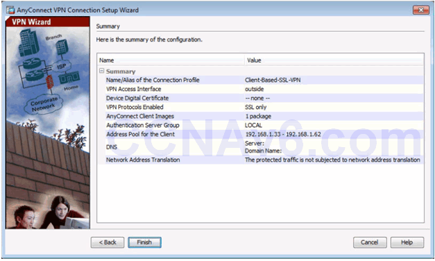
Summary Window
10.2.4.8 Verifying AnyConnect Connection
AnyConnect Connection Profiles Page
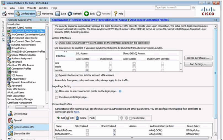
Verifying the Client-Based Configuration

10.2.4.9 Install the AnyConnect Client
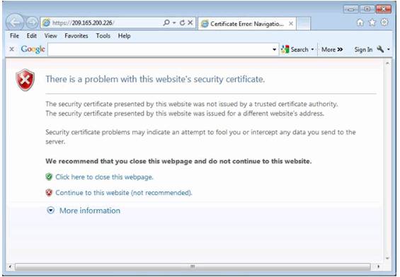
Security Certificate Window
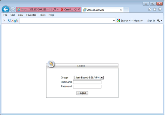
Logon Window
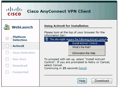
Cisco AnyConnect VPN Client Window
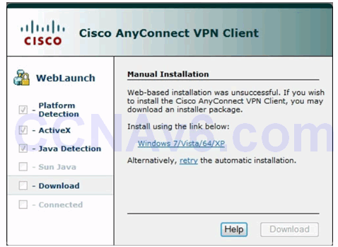
Manual Installation Window
Run Installer Window

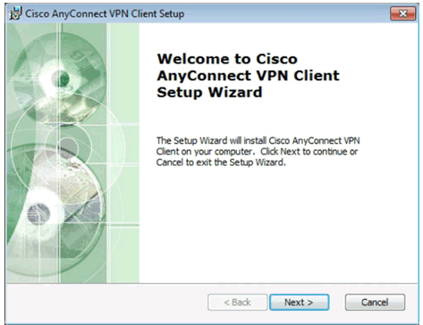
Cisco AnyConnect VPN Client Setup Window
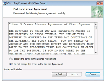
End-User Agreement Window
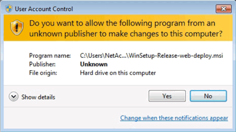
User Account Control Security Window
Ready to Install AnyConnect Client
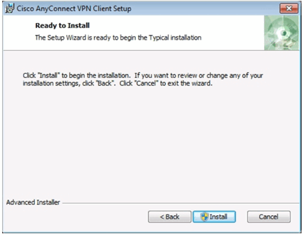
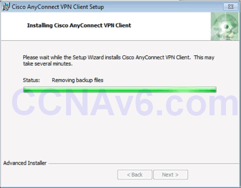
Installing the AnyConnect Client
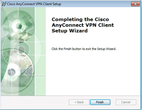
Complete Cisco AnyConnect VPN Installation
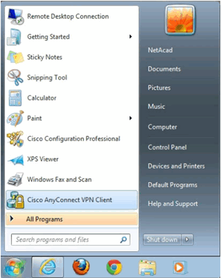
Start the Cisco AnyConnect VPN Cisco
Cisco AnyConnect VPN Client Window
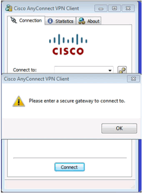
Cisco AnyConnect VPN Connect Window
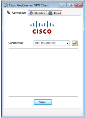
Certificate Security Warning Window

Cisco AnyConnect VPN Authentication Window
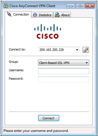
Cisco AnyConnect VPN Icon in System Tray
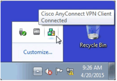
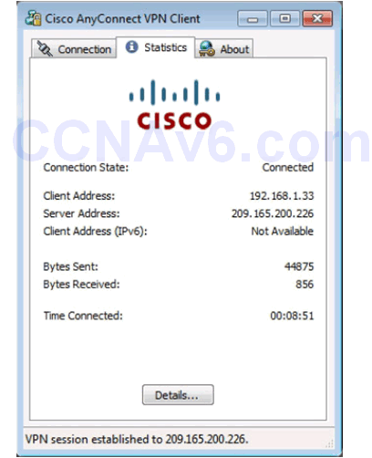
Cisco AnyConnect VPN Client Status
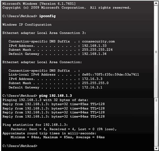
Verifying Connectivity to Internal Network
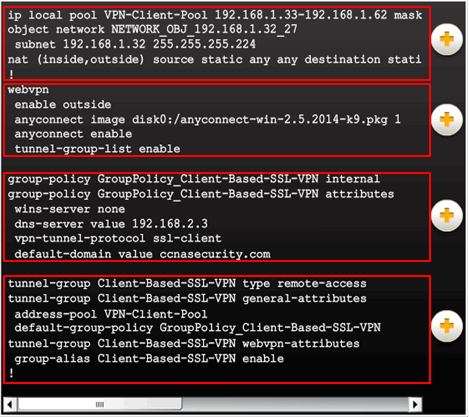
10.2.4.12 Viewing the Generated CLI Config
AnyConnect SSL VPN Configuration settings:
- NAT
- WebVPN
- Group policy
- Tunnel group
10.3 Summary
10.3.1 Conclusion
10.3.1.1 Lab – Configure Clientless Remote Access SSL VPNs Using ASDM
10.3.1.1 Lab – Configure Clientless Remote Access SSL VPNs Using ASA 5505 ASDM
10.3.1.1 Lab – Configure Clientless Remote Access SSL VPNs Using ASA 5506-X ASDM
Modeling Activity – Make it happen!
In this activity, you will apply new knowledge of application layer protocols and methods of the TCP/IP layer in streamlining data/network communication.

Network applications use protocols to facilitate data communication…
- POP
- IMAP
- HTTP
- FTP
…and the list goes on!
10.3.1.2 Lab – Configure AnyConnect Remote Access SSL VPNs Using ASDM
10.3.1.2 Lab – Configure AnyConnect Remote Access SSL VPN Using ASA 5505 ASDM
10.3.1.2 Lab – Configure AnyConnect Remote Access SSL VPN Using ASA 5506-X ASDM
Packet Tracer – Explore a Network
This simulation activity is intended to help you understand the flow of traffic and the contents of data packets as they traverse a complex network. Communications will be examined at three different locations simulating typical business and home networks.
10.3.1.3 Chapter 10: Advanced Cisco Adaptive Security Appliance
Packet Tracer – Multiuser – Tutorial
The multiuser feature in Packet Tracer allows multiple point-to-point connections between multiple instances of Packet Tracer. This first Packet Tracer Multiuser (PTMU) activity is a quick tutorial demonstrating the steps to establish and verify a multiuser connection to another instance of Packet Tracer within the same LAN. Ideally, this activity is meant for two students. However, it can also be completed as a solo activity simply by opening the two separate files to create two separate instances of Packet Tracer on your local machine.
