Instructor Planning Guide
Activities
What activities are associated with this chapter?


Assessment
Students should complete Chapter 8, “Assessment” after completing Chapter 8.
Quizzes, labs, Packet Tracers and other activities can be used to informally assess student progress.
Sections & Objectives
8.1 Troubleshooting Methodology
Explain troubleshooting approaches for various network problems.
Explain how network documentation is developed and used to troubleshoot network issues.
Describe the general troubleshooting process.
Compare troubleshooting methods that use a systematic, layered approach.
8.2 Troubleshooting Scenarios
Troubleshoot end-to-end connectivity in a small to medium-sized business network, using a systematic approach.
Use an ICMP echo-based IP SLA to troubleshoot network connectivity issues.
Describe different networking troubleshooting tools.
Determine the symptoms and causes of network problems using a layered model.
Troubleshoot a network using the layered model.
Chapter 8: Network Troubleshooting
8.1 – Troubleshooting Methodology
8.1.1 – Network Documentation
8.1.1.1 – Documenting the Network
For troubleshooting purposes, network administrators must have a complete set of accurate and current network documentation which includes:
- Configuration files, including network configure files and end-system configuration files
- Physical and logical topology diagrams
- Baseline performance levels
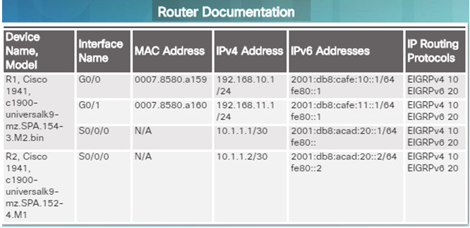
Network Configuration files should contain all relevant information about any devices including:
- Type of device, model designation
- IOS image name
- Device network hostname
- Location of the device
- If modular, include module/slot info
- If modular, include module/slot info
- Data link and network layer addresses
- Any additional important information about physical aspects of the device
End-system configuration files focus on the hardware and software used on end-system devices such as servers, network management consoles, and user workstations. Documentation should include:
- Device name (purpose)
- Operating system and version
- IPv4 and IPv6 addresses
- Subnet mask and prefix length
- Default gateway and DNS server
- Any high-bandwidth network applications used on the end system
8.1.1.2 – Network Topology Diagrams
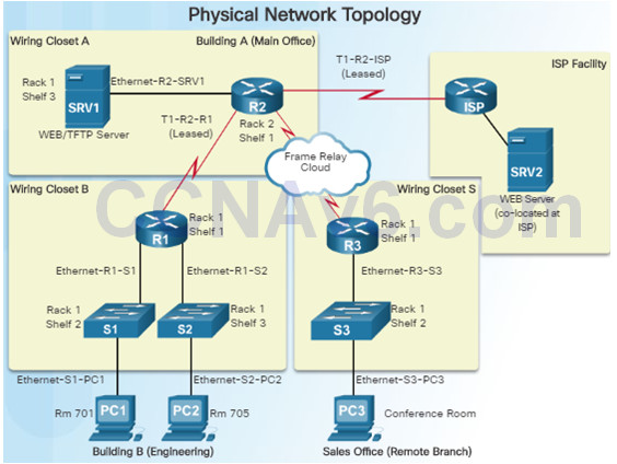
Network topology diagrams keep track of the location, function, and status of devices on the network. There are two types of topology diagrams:
- Physical topology
- Logical topology
Physical Topology network diagrams show the physical layout of the devices connected to the network and typically include:
- Device type
- Model and manufacturer
- Operating System version
- Cable type and identifier
- Cable specification
- Connector type
- Cabling endpoints
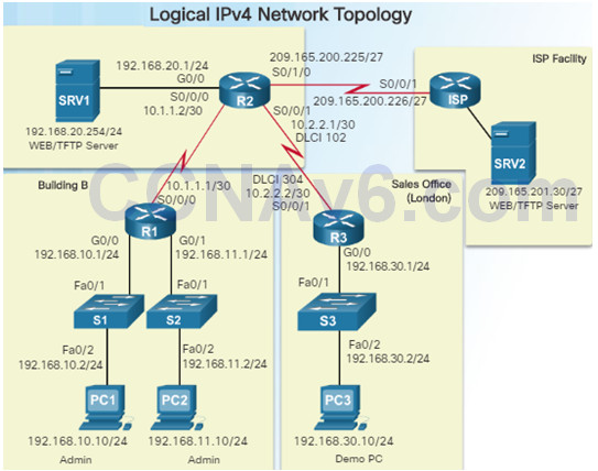
Logical network topology diagrams illustrate how devices are logically connected to the network
Symbols are used to represent network elements, such as routers, servers, hosts, VPN concentrators, and security devices.
Documented information might include:
- Device identifiers
- IP address and prefix lengths
- Interface identifiers
- Connection type
- Frame Relay DLCI for virtual circuits (if applicable)
- Site-to-site VPNs
- Routing protocols and static routes
- WAN technologies used
- Data-link protocols
8.1.1.3 – Establishing a Network Baseline
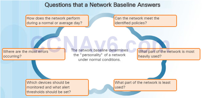
The purpose of network monitoring is to watch network performance in comparison to a predetermined baseline.
A network performance baseline
- Is used to establish normal network or system performance
- Requires collecting performance data from the ports and devices that are essential to operation
- Allows the network administrator to determine the difference between abnormal behavior and proper network performance
Analysis after an initial baseline also tends to reveal hidden problems. The collected data can show the true nature of congestion or potential congestion in a network.
8.1.1.4 – Steps to Establish a Network Baseline
Step 1: Determine what types of data to collect.
Start out with a few variables that represent the defined policy.
Not that capturing too many data points can be overwhelming making analysis difficult.
Start out simply, and fine-tune along the way.
Step 2: Identify devices and ports of interest.
Use the network topology to identify key devices for which performance data should be measured.
Devices and ports of interest include network device ports that connect to other network devices, servers, and key users.
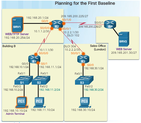
Step 3: Determine the baseline duration
The length of time and baseline information being gathered must be sufficient for establishing a typical picture of the network.
Daily trends of network traffic should be measured.
Monitor for trends that occur over a longer period of time such as weekly or monthly.
Capture data trends and include:
Screenshots of CPU utilization trends captured over a daily, weekly, monthly, and yearly period
Note: Baseline measurements should not be performed during times of unique traffic patterns.
8.1.1.5 – Measuring Data
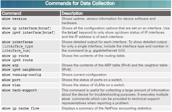
When documenting the network, it is necessary to gather information directly from routers and switches.
Ping, traceroute, and telnet are useful commands to document.
The figure to the left lists some of the most common Cisco IOS show commands used for data collection.
Manual data collection using show commands on individual network devices is very time consuming and is not a scalable solution. This should be reserved for smaller networks or mission critical devices.
Sophisticated network management software is typically used to baseline large and complex networks.
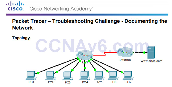
8.1.1.8 – Packet Tracer – Troubleshooting Challenge – Documenting the Network
This activity covers the steps to take to discover a network using primarily the Telnet, show cdp neighbors detail, and show ip route commands.
The topology in the figure to the left does not reveal all of the details of the network.
You will be require to use your knowledge of networking and discovery commands to learn about the full network topology and document it.
8.1.1.8 Packet Tracer – Troubleshooting Challenge – Documenting The Network Instructions
8.1.2 – Troubleshooting Process
8.1.2.1 – General Troubleshooting Procedures
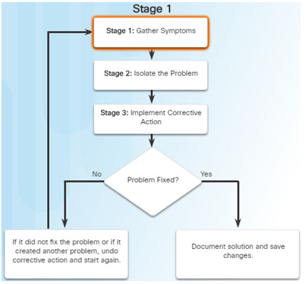
Using efficient troubleshooting techniques shortens overall troubleshooting time.
There are three major stages to the troubleshooting process:
Stage 1. Gather symptoms –
- Gather and document symptoms from the network, end systems, and users.
- The network administrator determines which network components have been affected and how the functionality of the network has changed in comparison to the baseline.
- Symptoms may come from the network management system, console messages, and user complaints.
- Ask questions and investigate the issue in order to localize the problem to a smaller range of possibilities.
Stage 2. Isolate the problem –
- Isolating is the process of eliminating variables until a single problem, or a set of related problems has been identified as the cause.
- The network administrator should examine the problems at the logical layer of the network so that the most likely cause can be detected.
Stage 3. Implement corrective action –
- After identifying the cause of the problem, the network administrator works to correct the problem by implementing, testing, and documenting possible solutions.
- Can the solution be implemented immediately, or does it need to be postponed?
- The severity of the problem should be weighed against the impact of the solution.
8.1.2.2 – Gathering Symptoms
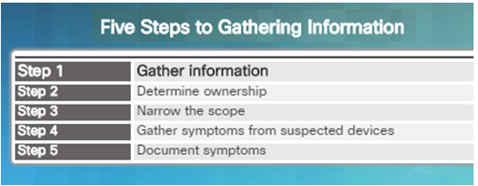
It is important to gather facts and evidence that will allow you to progressively eliminate possible causes, and eventually identify the root cause of the issue.
There are five information gathering steps:
Step 1. Gather Information
- Gather information from the trouble ticket, users, or end systems affected by the problem to form a definition of the problem.
Step 2. Determine ownership
- If the problem is within the control of the organization, move onto the next stage. If it is outside of the boundary of organizational control, contact an administrator for the external system.
Step 3. Narrow the scope
- Determine if the problem is at the core, distribution, or access layer.
- At the identified layer, analyze the existing symptoms and try to determine which piece of equipment is most likely the cause.
Step 4. Gather symptoms from suspect devices
- Using a layered troubleshooting approach, gather hardware and software symptoms from the suspect devices.
- Is it a hardware of software configuration problem?
Step 5. Document symptoms
- If the problem cannot be solved using the documented symptoms, begin the isolating stage of the general troubleshooting process.
- Gather symptoms from devices using commands/tools including: ping, traceroute, telnet, show, debug, device logs and packet captures.
8.1.2.3 – Questioning End Users
In many cases, the problem is reported by an end user. This information may often be misleading or vague.
This may require asking questions of end users to better help determine what the problem is.
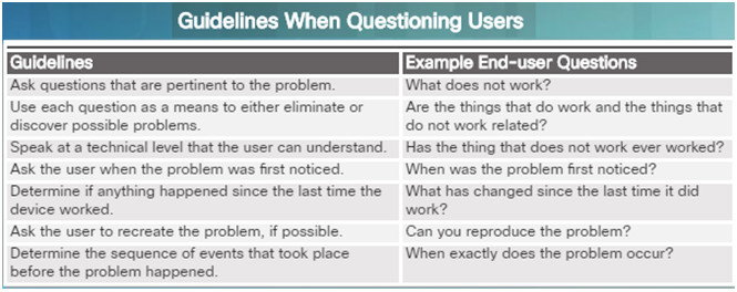
Use effective questioning techniques when asking the end users about a network problem they may be experiencing.
The table to the left provides some guidelines and sample end-user questions.
8.1.3 – Isolating the Issue Using Layered Models
8.1.3.1 – Using Layered Models for Troubleshooting
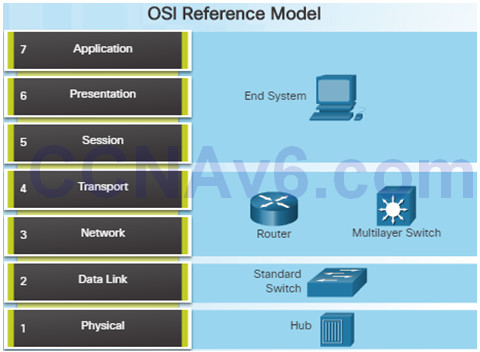
If no solution is identified, the network administrator compares the characteristics of the problem to the logical layers of the network to isolate and solve the issue.
The OSI reference model provides a common language for network administrators and is commonly used in troubleshooting networks.
Problems are typically described in terms of a given OSI model layer.
The OSI reference model describes how information from a software application in one computer moves through a network to a software application in another computer.
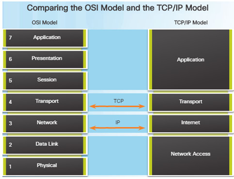
Similar to the OSI networking model, the TCP/IP networking model also divides networking architecture into modular layers.
The figure to the left shows how the two models map to each other.
The application layer in the TCP/IP suite combines the functions of the three OSI model layers: session, presentation, and application.
The TCP/IP network access layer corresponds to the OSI physical and data link layers.
8.1.3.2 –Troubleshooting Methods
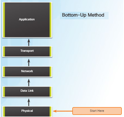
Using the layered models, there are three primary methods for troubleshooting networks and each has its advantages and disadvantages:
- Bottom-up
- Top-down
- Divide-and-conquer
Bottom-up Troubleshooting Method
- Start with the physical components of the network and move up through the layers of the OSI model until the cause of the problem is identified
- This is a good approach to use when the problem is suspected to be a physical one.
- Most networking problems reside at the lower levels, so using this method is often effective
- The disadvantage with this method is it requires that you check every device and interface on the network until the cause of the problem is found.
Top-Down Troubleshooting Method
- This method starts with troubleshooting the end-user applications and moves down through the layers of the OSI model until the cause of the problem has been identified.
- End-user applications are tested before tackling the more specific networking pieces.
- Use this approach for simpler problems.
- The disadvantage is that it requires checking every network application until the problem is found.
Divide-and-Conquer Troubleshooting Method
- The network administrator selects a layer and tests in both directions from that layer.
- Start by collecting user experiences of the problem, document the symptoms, and then, using that information, make an informed guess as to which OSI layer to start your investigation.
- If a layer is functioning properly, all layers below can be assumed to be functioning.
8.1.3.3 – Other Troubleshooting Methods
In addition to the systematic, layered approach to troubleshooting, there are also, less-structured approaches.
- Educated guess by the network administrator
- Guess is based on the symptoms of the problem
- This is more successful when implemented by seasoned network administrators who can rely on their extensive knowledge and experience
Comparing a working and non-working situation
- Look for differences between configurations, software versions, and hardware and other device properties.
- This method can be helpful when the network administrator is lacking an area of expertise or when the problem needs to be resolved quickly.
Substitution
- Involves swapping the problematic devices with known, working ones.
- If the problem remains, the network administrator knows to look elsewhere.
8.1.3.4 – Guidelines for Selecting a Troubleshooting Method
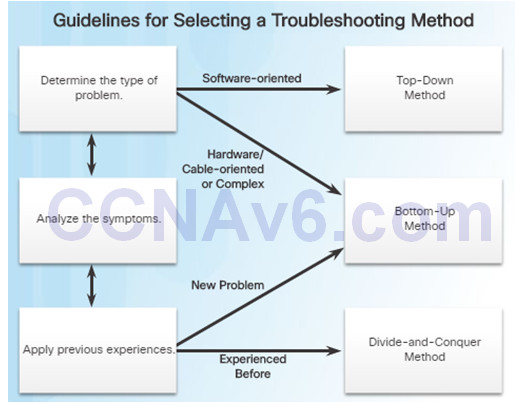
To quickly resolve network problems, take the time to select the most effective network troubleshooting method. An example:
- Two IP routers are not exchanging routing information.
- The last time this type of problem occurred, it was a protocol issue.
- Therefore, choose the divide-and-conquer troubleshooting method.
- Analysis reveals that there is connectivity between the routers.
- Start the troubleshooting process at the physical or data link layer.
- Confirm connectivity and begin testing the TCP/IP-related functions at the next layer up in the OSI model, the network layer.
8.2 – Troubleshooting Scenarios
8.2.1 – Using IP SLA
8.2.1.1 – IP SLA Concepts
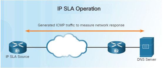
In the figure above, R1 is the IP SLA source that monitors the connection to the DNS server by periodically sending ICMP requests to the server.
Network administrators must discover network failures as early as possible.
- A useful tool for this task is the Cisco IOS IP Service Level Agreement (SLA).
- IP SLAs use generated traffic to measure network performance between two networking devices, multiple network locations, or across multiple network paths.
Network engineers use IP SLAs to simulate network data and IP services to collect network performance information in real time.
Additional benefits for using IP SLA’s include:
- SLA monitoring, measurement, and verification
- Monitoring to provide continuous, reliable, and predictable measurements (jitter, latency, packet loss)
- IP service network health assessment to verify that the existing QoS is sufficient for new IP services.
8.2.1.2 – IP SLA Configuration
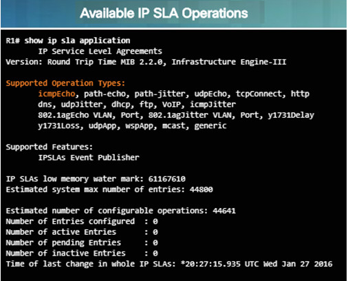
Instead of using ping manually, a network engineer can use IP SLA ICMP Echo operation to test the availability of network devices.
The IP SLA ICMP Echo operation provides the following measurements:
- Availability monitoring (packet loss statistics)
- Performance monitoring (latency and response time)
- Network operation (end-to-end connectivity)
show ip sla application – this privileged EXEC mode command verifies that the desired IP SLA operation is supported on the source device.
- The output in the figure confirms that R1 is capable of supporting IP SLA. However, there are no sessions configured.
To create an IP SLA operation and enter IP SLA configuration mode, use the ip sla operation-number global configuration command.
- The operation number is a unique number that is used to identify the operation being configured.
From IP SLA config mode, you can configure the IP SLA operation as an ICMP Echo operation and set the frequency rate:
- Router(config-ip-sla)# icmp-echo{ dest–ip-address| dest-hostname } [ source-ip { ip-address | hostname } | source-interface interface-id ]
- Router(config)# ip sla schedule operation-number [ life { forever | seconds}] [ start-time { hh: mm [: ss ] [ month day | day month ] | pending | now | after hh:mm:ss ] [ ageout seconds ] [ recurring ]
8.2.1.3 – Sample IP SLA Configuration
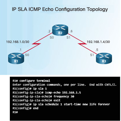
To help understand how to configure a simple IP SLA, refer to the figure and configuration commands to the left.
The configuration commands demonstrate how to configure an IP SLA operation with an operation number of 1.
- Multiple IP SLA operations may be configured on a device. Each operation can be referred to by its operation number.
- The icmp-echo command identifies the destination address to be monitored.
- The frequency command is setting the IP SLA rate to 30 second intervals.
The ip sla schedule command is scheduling the IP SLA operation number 1 to start immediately and continue until manually cancelled.
8.2.1.4 – Verifying an IP SLA Configuration
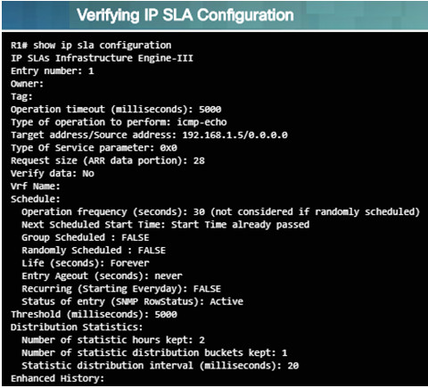
- Use the show ip sla configuration operation-number command to display configuration values
- In the figure to the left, the show ip sla configuration command displays the IP SLA ICMP Echo configuration.
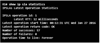
- Use the show ip sla statistics[operation-number] command to display the IP SLA operation monitoring statistics.
8.2.1.5 – Verifying an IP SLA Configuration
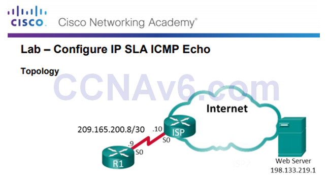
An outside vendor has been contracted to provide web services for your company.
As the network administrator, you have been asked to monitor the vendor’s service.
You decide to configure IP SLA to help with that task.
8.2.1.5 Lab – Configure IP SLA ICMP Echo
8.2.2 – Troubleshooting Tools
8.2.2.1 – Software Troubleshooting Tools
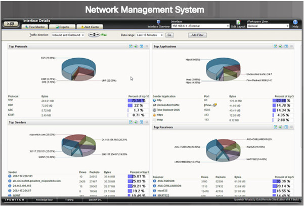
Common software troubleshooting tools include these:
Network Management System Tools
- NMS tools include device-level monitoring, configuration, and fault-management tools.
- These graphical tools can be used to investigate and correct network problems.
Knowledge Bases
- On-line network device vendor knowledge bases are very useful.
- When vendor-based knowledge bases are combined with Internet search engines, a network administrator has access to a vast pool of experience-based information.
Baselining Tools
- Many tools for automating the network documentation and baselining process are available. For example:
- SolarWinds Network Performance Monitor
8.2.2.2 – Protocol Analyzers
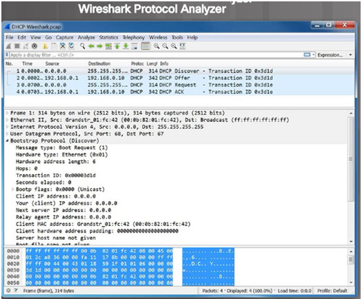
Protocol analyzers are useful to investigate packet content while the content is flowing through the network.
A protocol analyzer decodes the various protocol layers in a recorded frame and presents it in an easy to use format.
The figure to the left shows a screen capture of the Wireshark protocol analyzer.
Most protocol analyzers can filter traffic that meets certain criteria. For example, all traffic to and from a particular device can be captured.
Protocol analyzers are very helpful in troubleshooting network performance problems.
8.2.2.3 – Hardware Troubleshooting Tools
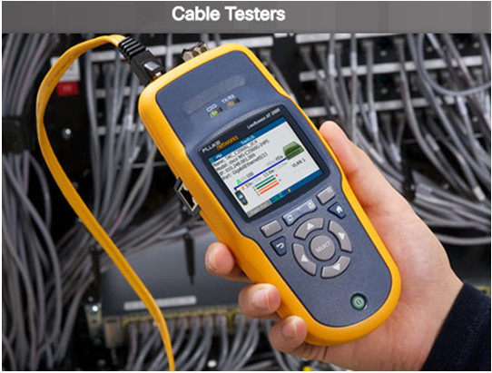
There are multiple types of hardware troubleshooting tools including:
- Digital Multimeters are test instruments that are used to directly measure electrical values of voltage, current, and resistance.
- Cable Testers are specialized handheld devices designed for testing the various types of data communication cabling. They can be used to detect broken wires, crossed-over wiring, shorted connections, and improperly paired connections. More expensive time-domain reflectometers (TDRs) are used to pinpoint the distance to a break in a cable.
- Cable Analyzers are multifunctional handheld devices that are used to test and certify copper and fiber cables for different services and standards.
Portable Network Analyzers are used for troubleshooting switched networks and VLANs.
- By plugging the network analyzer in anywhere on the network, a network engineer can see the switch port to which the devices is connected.
- They can also see the average and peak utilization as well as the VLAN configuration.
Network Analysis Module – The Cisco NAM is a device or software.
- It provides an embedded browser-based interface that generates reports on the traffic that consumes critical network resources.
- The NAM can capture and decode packets and track response times to pinpoint an application problem to a particular network or server.
8.2.2.4 – Hardware Troubleshooting Tools
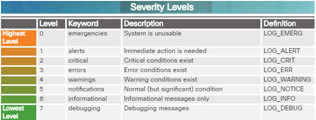
Cisco devices can send log messages to several different facilities including:
- Console
- Terminal lines
- Buffered logging
- SNMP traps
- External Syslog service
Syslog is a simple protocol used by an IP device known as a syslog client to send text-based log messages to another IP device known as the syslog server.
Implementing a logging facility is a very important part of network security and also for network troubleshooting.
Cisco devices can log various types of information including configuration changes, ACL violations, interface status, and many other types of events.
Cisco IOS log messages fall into one of eight levels as shown in the figure to the left. The lower the level number, the higher the severity level.
8.2.3 – Symptoms and Causes of Network Troubleshooting
8.2.3.1 – Physical Layer Troubleshooting
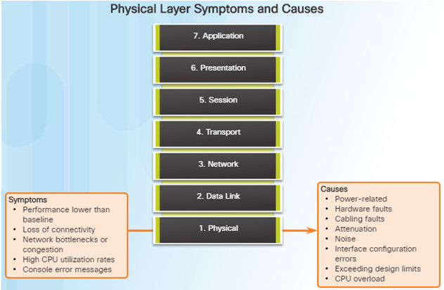
The physical layer is the only layer with physically tangible properties, such as wires, cards, and antennas.
Issues on a network often present as performance problems.
Because the upper layers of the OSI model depend on the physical layer to function, a network administrator must have the ability to effectively isolate and correct problems at this layer.
Common symptoms of network problems at the physical layer include:
- Performance lower than baseline
- Loss of connectivity
- Network bottlenecks or congestion
- High CPU utilization rates
- Console error messages
Issues that commonly cause network problems at the physical layer include:
- Power-related
- Hardware faults
- Cabling faults
- Attenuation
- Noise
- Interface-configuration errors
- Exceeding design limits
- CPU overload
8.2.3.2 – Data Link Layer Troubleshooting
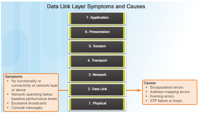
Troubleshooting Layer 2 problems can be a challenging process.
Layer 2 problems cause specific symptoms that, when recognized, will help identify the problem quickly:
- No functionality or connectivity at the network layer or above
- Network is operating below baseline performance levels
- Excessive broadcasts
- Most common Layer 2 console message is: “line protocol down”
Issues at the data link layer that commonly result in network connectivity or performance problems include these:
- Encapsulation errors
- Encapsulation at one end of a WAN link is configured differently from that on the other end.
- Address mapping errors
- In a point-to-multipoint or broadcast Ethernet topology, it is essential that an appropriate Layer 2 destination address be given to the frame.
- Framing errors
- A framing error occurs when a frame does not end on an 8-bit byte boundary.
- Spanning Tree Protocol (STP) failures or loops.
- Most STP problems are related to forwarding loops that occur when no ports in a redundant topology are blocked and traffic is forwarded in circles indefinitely.
8.2.3.3 – Network Layer Troubleshooting
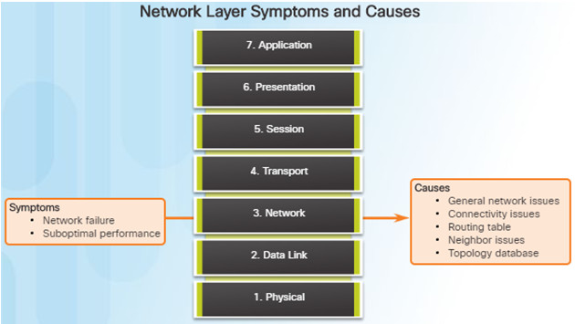
Network layer problems include any problem that involves a Layer 3 protocol (routed or routing protocols)
Common symptoms of network layer problems:
- Network failure
- Suboptimal performance
Areas to explore when diagnosing a possible problem involving routing protocols:
- General network issues
- Connectivity issues – Also check for Layer 1 or power issues
- Routing table issues – use debug
- Neighbor issues – check for adjacencies if used
- Check the routing table topology database
8.2.3.4 – Transport Layer Troubleshooting – ACLs
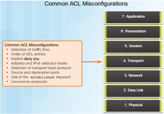
Network problems can arise from transport layer problems on the router. Improper ACL configuration issues might include:
- Wrong selection of traffic flow (inbound/outbound)
- Incorrect order of access control entries
- Implicit deny any
- Misconfiguration of addresses and IPv4 wildcard masks
- Selecting both UDP and TCP protocols when unsure
- Incorrect source and destination ports
- Incorrect use of the established keyword
- Misconfiguration of uncommon protocols such as VPN and encryption protocols
8.2.3.5 – Transport Layer Troubleshooting – NAT for IPv4
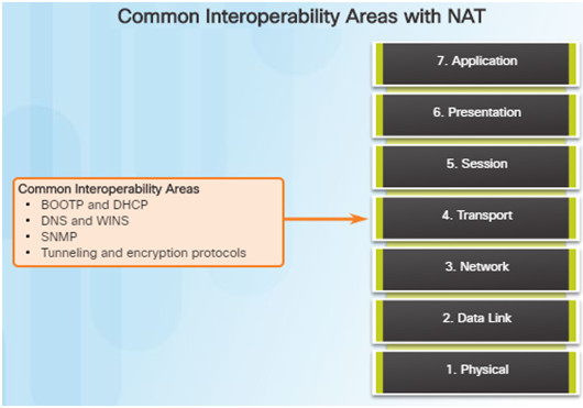
There are a number of problems with NAT such as not interacting with services like DHCP and tunneling.
These can include misconfigured NAT inside, NAT outside, or a misconfigured ACL.
Other issues include interoperability with other network technologies including:
- BOOTP and DHCP
- DNS
- SNMP
- Tunneling and encryption protocols
8.2.3.6 – Application Layer Troubleshooting
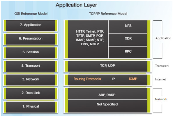
Most of the application layer protocols provide user services for network management, file transfer, distributed file services, terminal emulation, and email.
The most widely known and implemented TCP/IP application layer protocols include:
- SSH/Telnet, HTTP, FTP, TFTP
- SMTP, POP, SNMP, DNS, NFS
Application layer problems prevent services from being provided to application programs.
A problem at the application layer can result in unreachable or unusable resources when the physical, data link, network, and transport layers are functional.
8.2.4 – Troubleshooting IP Connectivity
8.2.4.1 – Application Layer Troubleshooting
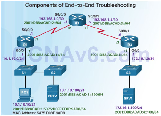
By employing a structured approach to the troubleshooting process, an administrator can reduce the time it takes to diagnose and solve a problem.
Throughout this topic, the following scenario (see figure) is used. The client host PC1 is unable to access applications on server SRV1 or server SRV2.
PC1 uses SLAAC with EUI-64 to create its IPv6 global unicast address. EUI-64 creates the Interface ID using the Ethernet MAC address, inserting FFFE in the middle, and flipping the seventh bit.
Here are the steps an administrator can take when troubleshooting with the bottom-up approach:
Step 1.Check physical connectivity at the point where network communication stops.
Step 2.Check for duplex mismatches.
Step 3.Check data link and network layer addressing on the local network.
Step 4.Verify that the default gateway is correct.
Step 5.Ensure that devices are determining the correct path from the source to the destination. Manipulate the routing information if necessary.
Step 6.Verify that the transport layer is functioning properly (Telnet can be used).
Step 7.Verify that there are no ACLs blocking traffic.
Step 8.Ensure that DNS settings are correct. There should be a DNS server that is accessible.
8.2.4.2 – End-to-End Connectivity Problem Initiates Troubleshooting
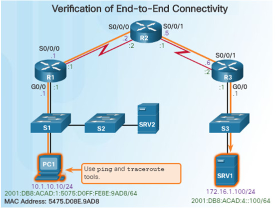
Ping and traceroute are the two most common utilities to test end-to-end connectivity.
The ping command uses a Layer 3 protocol that is a part of the TCP/IP suite called ICMP.
- ping uses the ICMP echo request and ICMP echo reply packets.
- ping can be used for IPv4 and IPv6
The traceroute command illustrates the path the IPv4 packets take to reach their destination.
- The Cisco IOS traceroute command can be used for both IPv4 and IPv6
- The tracert command can be used on Windows
The traceroute command is commonly performed when the ping command fails.
8.2.4.3 – Step 1 – Verify the Physical Layer
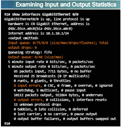
When a network administrator determines that a problem exists on a given device, and that problem might be hardware-related, it is useful to verify its operation using the following IOS commands:
- show processes cpu
- show memory
- show interfaces
When troubleshooting performance-related issues and hardware is suspected to be at fault, use the show interfaces command. The output will show the following:
- Input queue drops
- Output queue drops
- Input errors
- Output errors
8.2.4.4 – Step 2 – Check for Duplex Mismatches
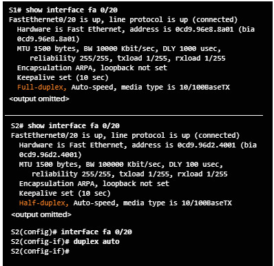
Duplex mismatch between two ends of an Ethernet link is another common cause for interface errors.
The IEEE 802.3ab Gigabit Ethernet standard mandates the use of autonegotiation for speed and duplex. Most Fast Ethernet NICs also use autonegotiation by default.
However, if duplex negotiation fails for some reason, it might be necessary to set the speed and duplex manually on both ends.
Point-to-point Ethernet links should always run in full-duplex mode.
The use of autonegotiation for speed and duplex is the current recommended practice.
8.2.4.5 – Step 3 – Verify Layer 2 and Layer 3 Addressing on the Local Network
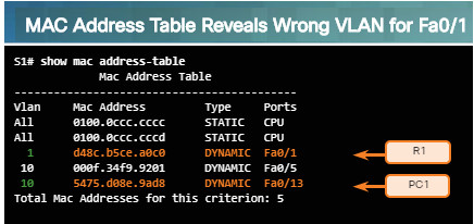
Look for VLAN assignment issues when troubleshooting end-to-end connectivity issues using the show vlan command on a switch.
The output of the show mac address-table command can also be helpful when looking for VLAN assignment issues. This command is used to display the MAC address table on the switch, but also includes VLAN information.
The arp Windows command can be used to help verify mappings between destination IP addresses and Layer 2 Ethernet addresses.
- The arp –d command can be used to clear the arp cache and allow it to repopulate with updated info.
The netsh interface ipv6 show neighbor Windows command will list all devices that are currently in the neighbor table.
- By examining the neighbor table, the network administrator can verify that the destination IPv6 addresses map to correct Ethernet addresses.
The show ipv6 neighbors command can be used on a Cisco IOS router.
8.2.4.6 – Step 4 – Verify Default Gateway
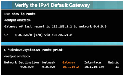
These commands will help verify the presence of the IPv4 default gateway.
If there is no default route on the router or if the host is configured with the wrong default gateway, then communication between two endpoints on different networks will not work.
In addition to the commands in the figure, the following can be useful when troubleshooting:
- Use the show ipv6 route Cisco IOS command to check for the IPv6 default route on R1 and use the ipconfig Windows command to verify if a PC has an IPv6 default gateway
- The show ipv6 interface GigabitEthernet 0/0 command can verify if it is a member of the correct multicast group.
- Use the ipconfig command on Windows PCs to verify if the correct default gateway is set.
8.2.4.7 – Verify Correct Path
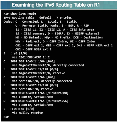
When troubleshooting a connectivity issue, it is often necessary to verify the path to the destination network.
Use either the show ip route or show ipv6 route command to verify that the route exists to the destination device/network.
The process of forwarding IPv4 and IPv6 packets is based on the longest bit match or longest prefix match. If the destination address in a packet:
- Does not match an entry in the routing table, then the default route is used. If there’s no default route, the packet is discarded.
- Matches a single entry in the routing table, then the packet is forwarded through the interface that is defined in this route.
- Matches more than one entry in the routing table and the routing entries have the same prefix length, then the packets for this destination can be distributed among the routes that are defined in the routing table.
8.2.4.8 – Verify the Transport Layer
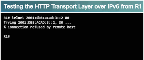
The output above shows a successful Telnet connection from R1 to R3, over IPv6 using port 80.
The output verifies a successful transport layer connection.
If the network layer appears to be functioning as expected, but users are still unable to access resources, then the network administrator must begin troubleshooting the upper layers.
The two most common issues that affect transport layer connectivity are ACL and NAT configuration problems.
A common tool for testing transport layer functionality is the Telnet utility.
If a ping is successful to a server, then the network administrator knows that all layers below the network layer, between the user and the server are operational.
- The administrator knows the issue is with Layer 4 or up.
For example: R1# telnet 2001:db8:acad:3::2
8.2.4.9 – Step 7 – Verify ACLs
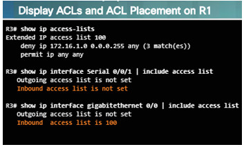
On routers, there may be ACLs configured that prohibit protocols from passing through the interface in the inbound or outbound direction. Use the following commands to display the contents of all ACLs:
- show ip access-lists
- show ipv6 access-list
Use the following commands to see if there are ACLs set on a particular interface:
- show ip interfaces
- show ipv6 interfaces
8.2.4.10 – Step 8 – Verify DNS
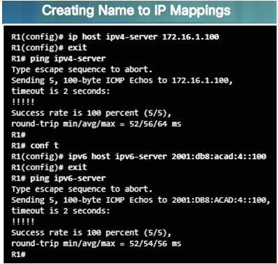
The DNS protocol controls the DNS, a distributed database with which you can map hostnames to IP addresses.
When DNS is configured on a device, you can substitute the hostname for the IP address for all IP commands including ping and telnet.
If there is no DNS server configured on a device, you can use the ip host command to enter name to IPv4 mappings on a switch or router.
The ipv6 host command is used for IPv6.
The figure to the left demonstrates the use of these commands.
8.2.4.12 – Packet Tracer – Troubleshooting Enterprise Networks 1
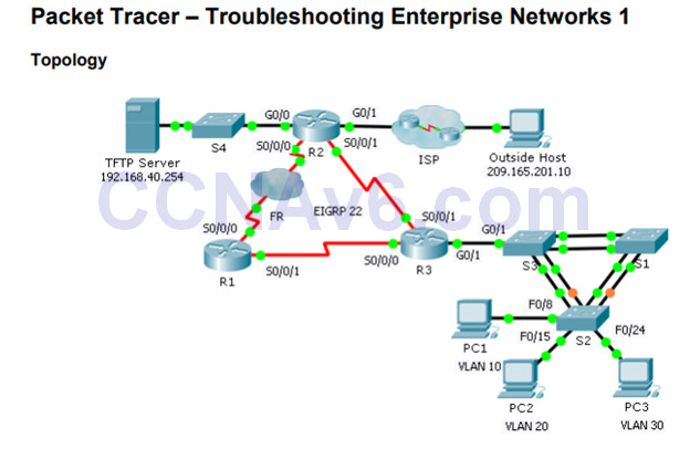
This activity uses a variety of technologies you have encountered during your CCNA studies, including VLANs, STP, routing, inter-VLAN routing, DHCP, NAT, PPP, and Frame Relay.
You will be tasked with reviewing the requirements, isolating and resolving any issues, as well as documenting the steps you took to verify the requirements.
8.2.4.12 Packet Tracer – Troubleshooting Enterprise Networks 1 Instructions
8.2.4.13 – Packet Tracer – Troubleshooting Enterprise Networks 2
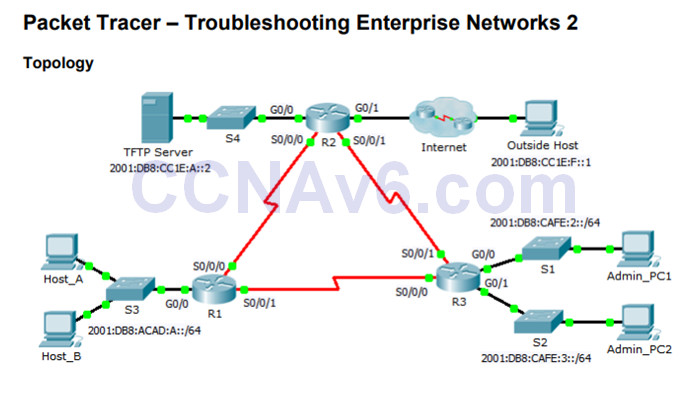
This activity uses IPv6 configurations that include DHCPv6, EIGRPv6, and IPv6 default routing.
Your task is to review the requirements, isolate and resolve any issues, and then document the steps you took to verify the requirements.
8.2.4.13 Packet Tracer – Troubleshooting Enterprise Networks 2 Instructions
8.2.4.14 – Packet Tracer – Troubleshooting Enterprise Networks 3
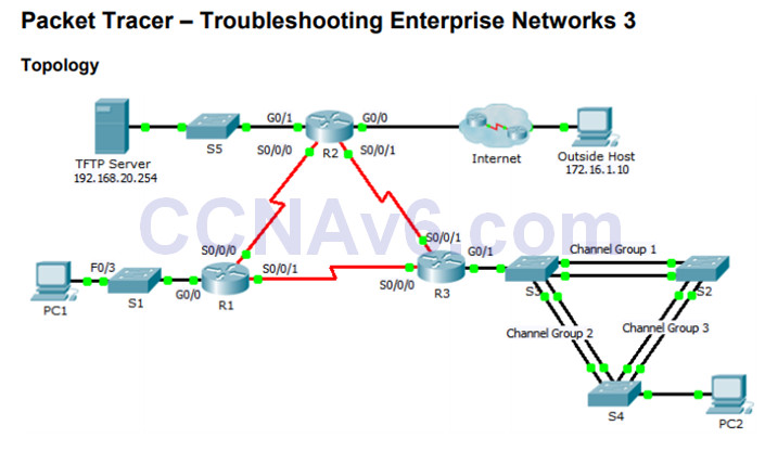
8.2.4.14 Packet Tracer – Troubleshooting Enterprise Networks 3 Instructions
This activity uses a variety of technologies you have encountered during your CCNA studies, including routing, port security, EtherChannel, DHCP, NAT, PPP, and Frame Relay.
Your task is to review the requirements, isolate and resolve any issues, and then document the steps you took to verify the requirements.
8.2.4.15 – Packet Tracer – Troubleshooting Challenge – Using Documentation to Solve Issues
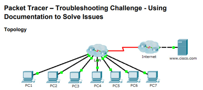
This is Part II of a two-part activity.
Part I is Packet Tracer – Troubleshooting Challenge – Documenting the Network, which you should have completed earlier in the chapter.
In Part II, you will use your troubleshooting skills and documentation from Part I to solve connectivity issues between PCs.
8.2.4.15 Packet Tracer – Troubleshooting Challenge – Using Documentation to Solve Issues
8.3 – Summary
8.3.1 – Conclusion
8.3.1.1 – Chapter 8: Network Troubleshooting
Explain troubleshooting approaches for various network problems.
8.3.1.1 Documentation Development Instructions
Troubleshoot end-to-end connectivity in a small to medium-sized business network, using a systematic approach.
8.3.1.2 – Packet Tracer – CCNA Skills Integration Challenge
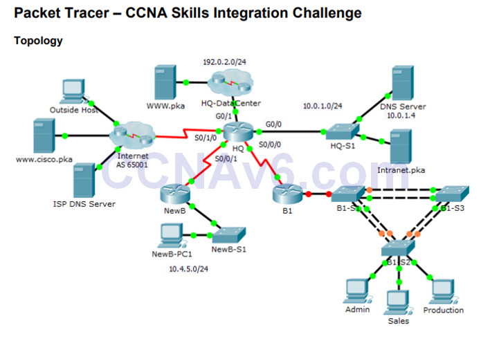
In this comprehensive CCNA skills activity, the XYZ Corporation uses a combination of eBGP and PPP for WAN connections.
Other technologies include NAT, DHCP, static and default routing, EIGRP for IPv4, inter-VLAN routing, and VLAN configurations. Security configurations include SSH, port security, switch security, and ACLs.
This activity will require the configuration of these technologies as well as verification for full connectivity from each PC to the web servers.
8.3.1.2 Packet Tracer – CCNA Skills Integration Challenge Instructions
