Instructor Planning Guide
Activities
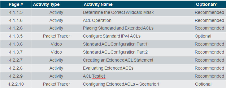
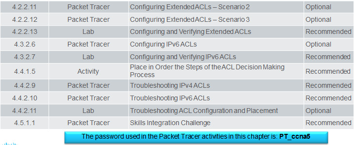
What activities are associated with this chapter?
Assessment
Students should complete Chapter 4, “Assessment” after completing Chapter 4.
Quizzes, labs, Packet Tracers and other activities can be used to informally assess student progress.
Sections & Objectives
4.1 Standard ACL Operation and Configuration
Configure standard IPv4 ACLs.
Explain the purpose and operation of ACLs in small to medium-sized business networks.
Compare standard and extended IPv4 ACLs.
Configure standard IPv4 ACLs to filter traffic in a small to medium-sized business network.
4.2 Extended IPv4 ACLs
Configure extended IPv4 ACLs.
Explain the structure of an extended access control entry (ACE).
Configure extended IPv4 ACLs to filter traffic according to networking requirements.
4.3 IPv6 ACLs
Configure IPv6 ACLs.
Compare IPv4 and IPv6 ACL creation.
Configure IPv6 ACLs to filter traffic according to networking requirements.
4.4 Troubleshoot ACLs
Troubleshoot ACLs.
Explain how a router processes packets when an ACL is applied.
Troubleshoot common ACL errors using CLI commands.
Chapter 4: Access Control Lists
4.1 – Advanced Single-Area OSPF Configurations
4.1.1 – ACL Operation Overview
4.1.1.1 – ACLs and the Wildcard Mask
An ACL contains a sequential list of permit or deny statements, known as access control entries (ACEs).
- ACEs are also commonly called ACL statements.
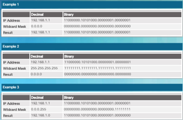
- IPv4 ACEs include the use of wildcard masks which are a string of 32 binary digits used by the router to determine which bits of the address to examine for a match.
4.1.1.2 – Applying ACLs to an Interface
You can configure:
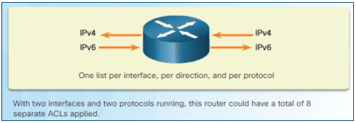
- One ACL per protocol – To control traffic flow on an interface, an ACL must be defined for each protocol enabled on the interface.
- One ACL per direction – ACLs control traffic in one direction at a time on an interface. Two separate ACLs must be created to control inbound and outbound traffic.
- One ACL per interface – ACLs control traffic for an interface, for example, GigabitEthernet 0/0.
4.1.1.3 – A TCP Conversation
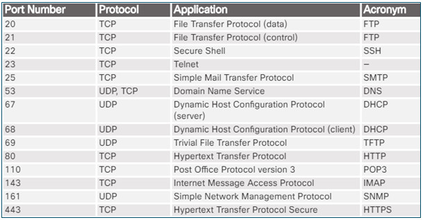
- Extended ACLs can filter traffic by examining TCP port numbers.
- Common TCP and UDP ports numbers include:
4.1.1.4 – ACL Packet Filtering
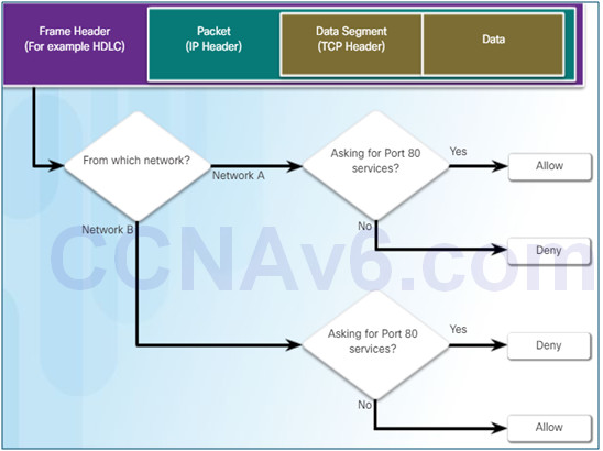
To help explain how an ACL operates, refer to the decision path used to filter web traffic.
An ACL has been configured to:
- Permit web access to users from Network A but deny all other services to Network A users.
- Deny HTTP access to users from Network B, but permit network B users to have all other access.
4.1.2 – Types of IPv4 ACLs
4.1.2.1 – Standard and Extended IPv4 ACLs
Standard ACLs filter packets based on the source address only.
![]()
Extended ACLs filter packets based on:
Protocol type / Protocol number (e.g., IP, ICMP, UDP, TCP, …)
Source and destination IP addresses
Source and Destination TCP and UDP ports
![]()
4.1.2.2 – Numbered and Named ACLs
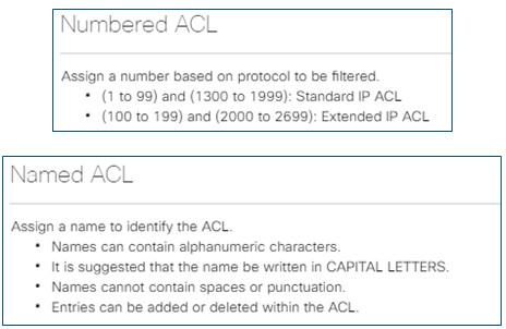
Standard and extended ACLs can be created using either a number or a name to identify the ACL and its list of statements.
4.1.2.3 – Where to Place ACLs
Extended ACLs should be located as close as possible to the source of the traffic to be filtered.
- Denies undesirable traffic close to the source network without crossing the network infrastructure.
Standard ACLs should be located as close to the destination as possible.
- If a standard ACL was placed at the source of the traffic, it would filter traffic based on the given source address no matter where the traffic is destined.

4.1.2.4 – Standard ACL Placement Example
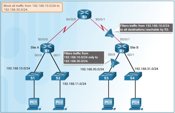
A standard ACL will be configured to block all traffic from 192.168.10.0/24 going to 192.168.30.0/24.
The standard ACL should be applied closest to the destination and therefore could be applied outgoing on the R3 G0/0 interface.
- Applying it incoming on the R3 S0/0/1 interface would prevent reaching 192.168.31.0/24 and therefore should not be applied to this interface.
4.1.2.5 – Extended ACL Placement Example
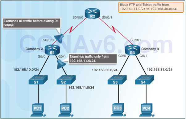
An extended ACL will be configured to block all FTP and Telnet traffic from 192.168.11.0/24 going to 192.168.30.0/24.
The extended ACL should be applied closest to the source and therefore could be applied incoming on the R1 G0/1 interface.
- Applying it outgoing on the R1 S0/0/1 interface would prevent reaching 192.168.31.0/24 but would also needlessly process packets from 192.168.10.0/24.
4.1.3 – Standard IPv4 ACL Implementation
4.1.3.1 – Configure a Standard IPv4 ACL
The full syntax of the standard ACL command is as follows:
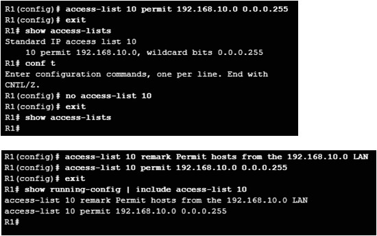
- access-list ACL-# {deny | permit | remark} source [source-wildcard][log]
For example:
- Permit all IP addresses in network 192.168.10.0/24
- Use the no access-list 10 command to remove an ACL.
- Use the remark keyword for documenting an ACL to make it easier to understand.
4.1.3.2 – Apply a Standard IPv4 ACL
An IPv4 ACL is linked to an interface using the following interface configuration mode command:
- ip access-group {ACL-# | access-list-name} {in | out}

Note:
To remove an ACL from an interface, first enter the no ip access-group command on the interface, and then enter the global no access-list command to remove the entire ACL.
4.1.3.3 – Named Standard IPv4 ACLs
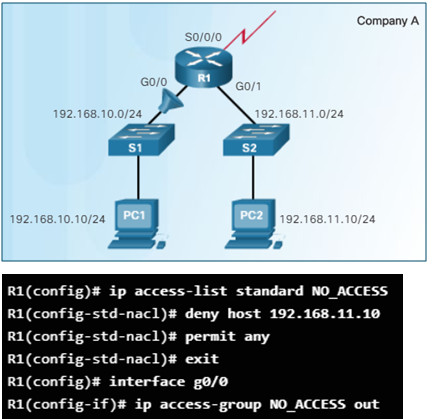
To create a standard named ACL.
- Use the ip access-list standard name global config command.
- Names are alphanumeric, case sensitive, and must be unique.
- The command enters standard named ACL configuration mode.
Use permit, deny, or remark statements.
Apply the ACL to an interface using the ip access-group name command.
4.1.3.4 – Verify ACLs
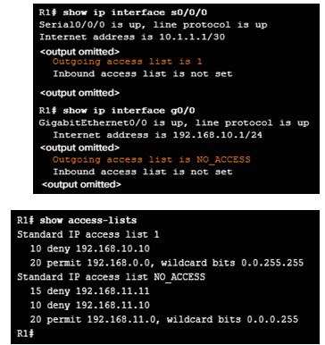
Use the show ip interface command to verify the ACL on the interface.
- The output includes the number or name of the access list and the direction in which the ACL was applied.
Use the show access-lists [ACL-# | access-list-name] command to view the content of a standard ACL.
- Notice that the NO_ACCESS statements are out of order because Cisco IOS uses a special hashing function for standard ACLs and re-orders host ACEs so they are processed first optimizing the search for a host ACL entry.
- Standard ACLs process network ACEs in the order in which they were entered.
4.1.3.5 – Packet Tracer – Configure Standard IPv4 ACLs

4.1.3.5 Packet Tracer – Configure Standard IPv4 ACLs
4.1.3.6 – Video Demonstration – Standard ACL Configuration Part 1
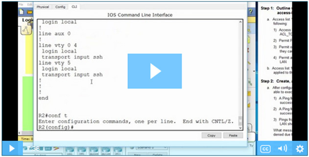
- In this video, configuration of standard IPv4 access lists is covered.
4.1.3.7 – Video Demonstration – Standard ACL Configuration Part 2
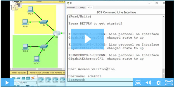
In this video, editing standard IPv4 access lists is covered. .
- ACLs can be edited using the ip access-list global configuration command.
4.2 – Extended IPv4 ACLs
4.2.1 – Structure of an Extended IPv4 ACLs
4.2.1.1 – Extended ACLs
Extended IPv4 ACLs provide more precise filtering.
- Extended ACLs are numbered 100 to 199 and 2000 to 2699, providing a total of 799 possible extended numbered ACLs.
- Extended ACLs can also be named.
- Extended ACLs are used more often than standard ACLs because they provide a greater degree of control.
4.2.1.2 – Filtering Ports and Services
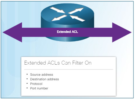
Extended ACLs can filter on protocol and port number.
An application can be specified by configuring either:
- The port number

- The name of a well-known port.

Note:
Use the question mark (?) to see available well-known port names.
E.g., access-list 101 permit tcp any any eq ?
4.2.2 – Configure Extended IPv4 ACLs
4.2.2.1 – Configuring Extended ACLs
The full syntax of the extended ACL command is as follows:
- access-list ACL-# {deny | permit | remark} protocol {source source-wildcard][operator [port-number | port-name]] {destination destination-wildcard][operator [port-number | port-name]]
For example:
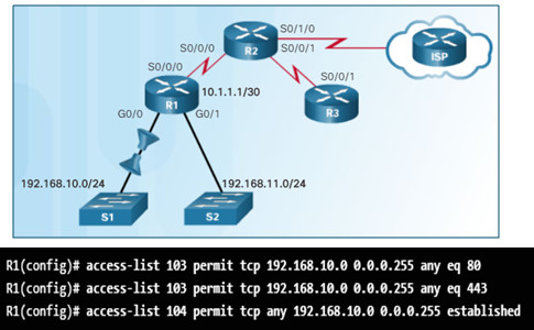
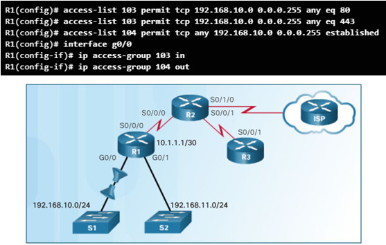
- ACL 103 allows requests to port 80 and 443.
- ACL 104 allows established HTTP and HTTPS replies.
- The established parameter allows only responses to traffic that originates from the 192.168.10.0/24 network to return to that network.
4.2.2.2 – Applying Extended ACLs to Interfaces
- Applying extended ACLs is similar to standard ACLs except that they should be applied as close to the source.
4.2.2.3 – Filtering Traffic with Extended ACLs
In this example, FTP traffic from subnet 192.168.11.0 going to subnet 192.168.10.0 is denied, but all other traffic is permitted.
- FTP utilizes two port numbers (TCP port 20 and 21) therefore two ACEs are required.
- The example uses the well-known port names ftp and ftp-data.
- Without at least one permit statement in an ACL, all traffic on the interface where that ACL was applied would be dropped.
- The ACL is applied incoming on the R1 G0/1 interface.

4.2.2.4 – Creating Named Extended ACLs
Named extended ACLs are created in the same way that named standard ACLs are created.
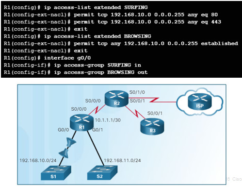
In this example, two named ACLs are created.
- SURFING permits users on the 192.168.10.0/24 network to exit going to ports 80 and 443.
- BROWSING enables return HTTP and HTTPs traffic.
4.2.2.5 – Verifying Extended ACLs
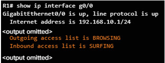
The show ip interface and show access-lists commands can be used to verify the content of extended ACLs.
The output and sequence numbers displayed in the show access-lists command output is the order in which the statements were entered.
- Unlike standard ACLs, extended ACLs do not implement the same internal logic and hashing function.
- Host entries are not automatically listed prior to range entries.

The show ip interface command is used to verify the ACL on the interface and the direction in which it was applied.
- The output from this command includes the number or name of the access list and the direction in which the ACL was applied.
4.2.2.6 – Editing Extended ACLs
An extended ACL can be edited in one of two ways:
Method 1 Text editor
- The ACL is copied and pasted into where the changes are made.
- The current access list is removed using the no access-list command.
- The modified ACL is then pasted back into the configuration.
Method 2 Sequence numbers
- Sequence numbers can be used to delete or insert an ACL statement.
- The ip access-list extended name command is used to enter named-ACL configuration mode.
- If the ACL is numbered instead of named, the ACL number is used in the name parameter.
- ACEs can be inserted or removed.
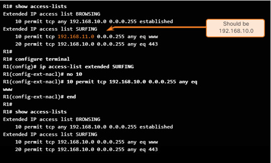
In this example, Method 2 is used to correct the named ACL SURFING which incorrectly permits 192.168.11.0/24 and is edited to permit 192.168.10.0/24.
4.2.2.10 – Packet Tracer – Configuring Extended ACLs – Scenario 1
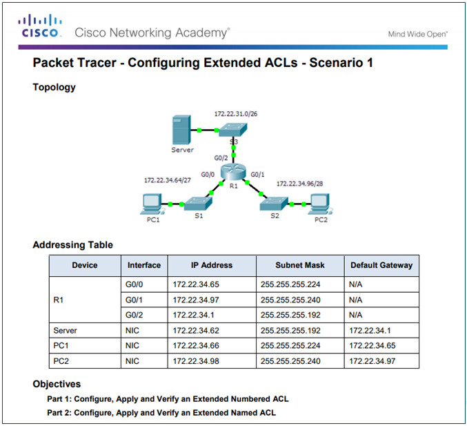
4.2.2.10 Packet Tracer – Configuring Extended ACLs Scenario 1
4.2.2.11 – Packet Tracer – Configuring Extended ACLs – Scenario 2
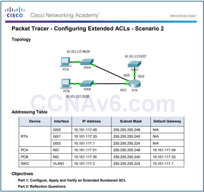
4.2.2.11 Packet Tracer – Configuring Extended ACLs Scenario 2
4.2.2.12 – Packet Tracer – Configuring Extended ACLs – Scenario 3

4.2.2.12 Packet Tracer – Configuring Extended ACLs Scenario 3
4.2.2.13 – Lab – Configuring and Verifying Extended ACLs
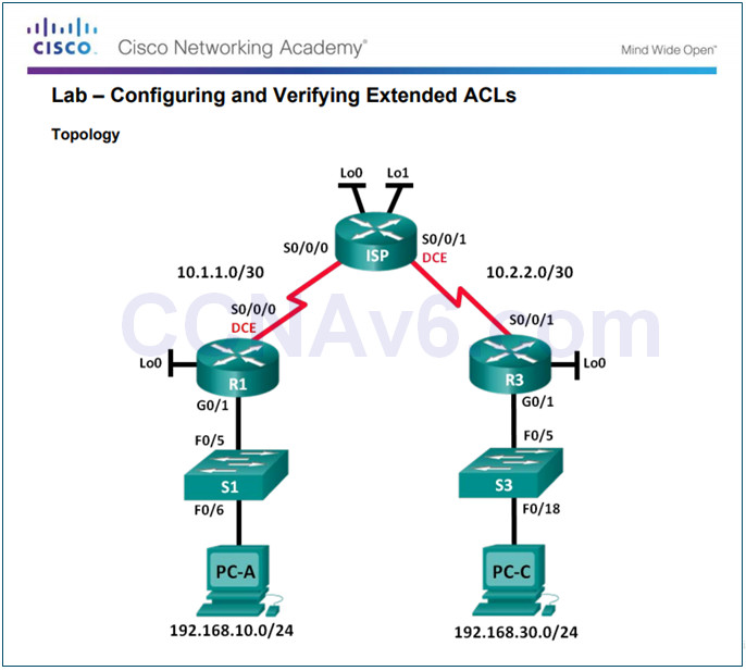
4.2.2.13 Lab – Configuring and Verifying Extended ACLs
4.3 – IPv6 ACLs
4.3.1 – IPv6 ACL Creation
4.3.1.1 – Types of IPv6 ACLs
IPv6 ACLs are similar to IPv4 ACLs in both operation and configuration.
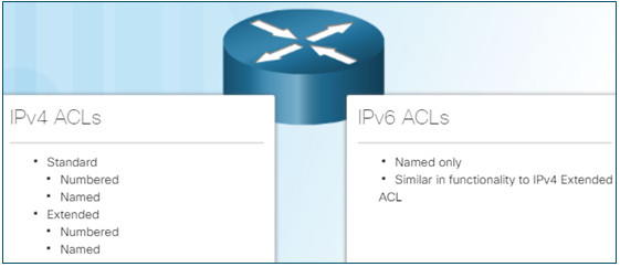
In IPv4 there are two types of ACLs, standard and extended and both types of ACLs can be either numbered or named ACLs.
With IPv6, there is only one type of ACL, which is equivalent to an IPv4 extended named ACL and there are no numbered ACLs in IPv6.
Note:
An IPv4 ACL and an IPv6 ACL cannot share the same name.
4.3.1.2 – Comparing IPv4 and IPv6 ACLs
There are three significant differences between IPv4 and IPv6 ACLs:
- The command used to apply an IPv6 ACL to an interface is ipv6 traffic-filter command.
- IPv6 ACLs do not use wildcard masks but instead specifies the prefix-length to indicate how much of an IPv6 source or destination address should be matched.
- An IPv6 ACL adds two implicit permit statements at the end of each IPv6 access list.
- permit icmp any any nd-na
- permit icmp any any nd-ns
- deny ipv6 any any statement
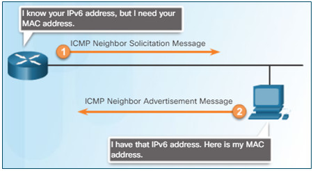
These two additional statements allow IPv6 ICMP Neighbor Discovery (ND) and Neighbor Solicitation (NS) messages to accomplish the same thing as IPv4 ARP.
4.3.2 – Configuring IPv6 ACLs
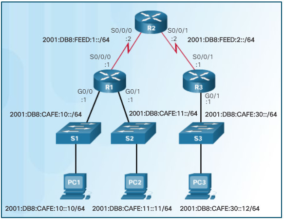
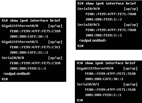
4.3.2.1 – Configuring IPv6 Topology
4.3.2.2 – Configuring IPv6 ACLs
In IPv6 there are only named ACLs and the configuration is similar to IPv4 extended named ACLs.

In this example:
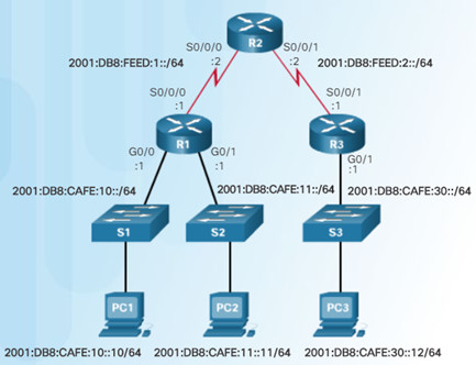
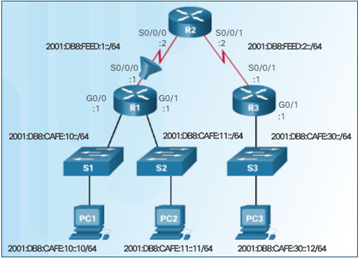
- The 1st statement names the IPv6 ACL NO-R3-LAN-ACCESS.
- The 2nd statement denies all IPv6 packets from the 2001:DB8:CAFE:30::/64 destined for any IPv6 network.
- The 3rd statement allows all other IPv6 packets.
4.3.2.3 – Applying an IPv6 ACL to an Interface
After an IPv6 ACL is configured, it is linked to an interface using the following interface command:
- ipv6 traffic-filter access-list-name {in | out}

The command applies the NO-R3-LAN-ACCESS IPv6 ACL inbound to the S0/0/0 interface of R1.
To remove an IPv6 ACL, enter the no ipv6 traffic-filter command on the interface, and then enter the global no ipv6 access-list command to remove the access list.
Note that IPv4 and IPv6 both use the access-class command to apply an access list to VTY ports.
4.3.2.4 – IPv6 ACL Examples
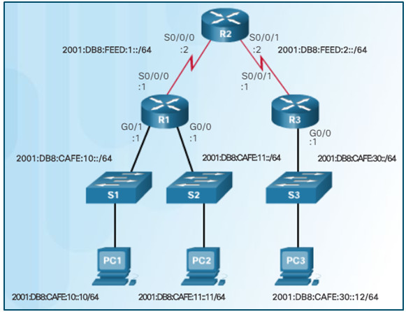
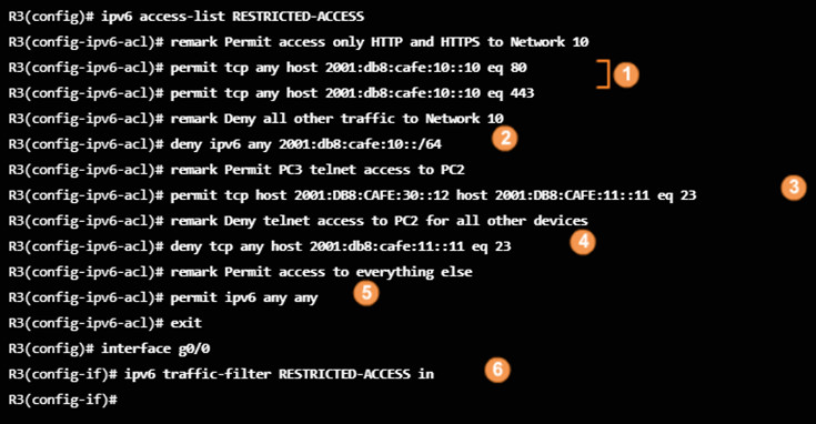
In this example, an IPv6 ACL permits R3 LAN users limited access to the LANs on R1.
- 1.These ACES allow access from any device to the web server (2001:DB8:CAFE:10::10).
- 2.All other devices are denied access to the 2001:DB8:CAFE:10::/64 network.
- 3.PC3 (2001:DB8:CAFE:30::12) is permitted Telnet access to PC2 (2001:DB8:CAFE:11::11).
- 4.All others are denied Telnet access to PC2.
- All other IPv6 traffic is permitted to all other destinations.
- 6.The IPv6 access list is applied inbound on G0/0 so only the 2001:DB8:CAFE:30::/64 network is affected.
4.3.2.5 – Verifying IPv6 ACLs
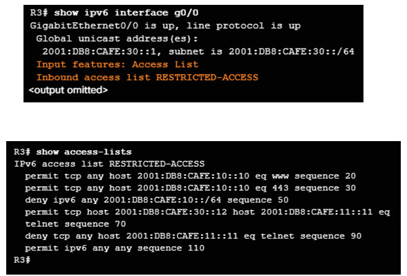
The commands used to verify an IPv6 access list are similar to those used for IPv4 ACLs.
- Use the show ipv6 interface command to see which ACL and direction is configured on an interface.
- Use the show access-lists command displays all configured IPv4 and IPv6 access lists
- Notice that IPv6 ACL sequence numbers are displayed at the end of the ACE.
The show running-config command displays all of the ACEs and remark statements.
4.3.2.6 – Packet Tracer – Configuring IPv6 ACLs
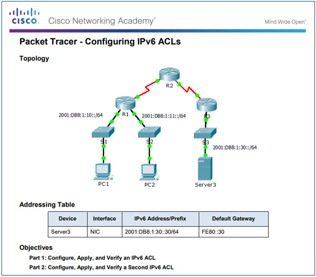
4.3.2.6 Packet Tracer – Configuring IPv6 ACLs
4.3.2.7 – Lab – Configuring and Verifying IPv6 ACLs
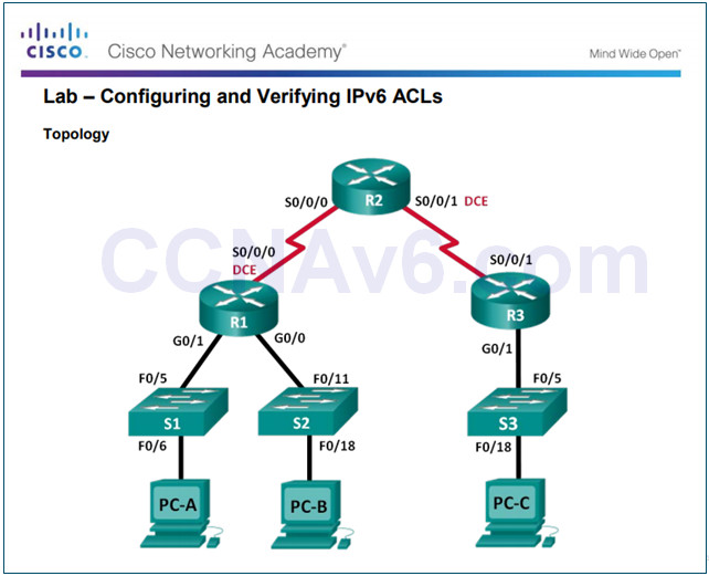
4.3.2.7 Lab – Configuring and Verifying IPv6 ACLs
4.4 – Troubleshoot ACLs
4.4.1 – Processing Packets with ACLs
4.4.1.1 – Inbound and Outbound ACL Logic
It is beneficial to consider how an inbound and outbound ACL is processed.
Inbound ACLs operate as follows:
- If the information in a packet header and an ACL statement match, the rest of the statements in the list are skipped, and the packet is permitted or denied as specified by the matched statement.
- If a packet header does not match an ACL statement, the packet is tested against the next statement in the list and this matching process continues until the end of the list is reached.
- At the end of every ACL is a statement is an implicit deny any statement and because of this statement, an ACL should have at least one permit statement in it; otherwise, the ACL blocks all traffic.
Outbound ACLs operate as follows:
- The router checks the routing table to see if the packet is routable.
- The router checks to see whether the outbound interface is grouped to an ACL.
- If it is, the ACL is tested by the combination of ACEs that are associated with that interface.
- Based on the ACL tests, the packet is permitted or denied.
4.4.1.2 – ACL Logic Operations
When a packet arrives at a router interface:
- The router checks to see whether the destination Layer 2 address matches its interface Layer 2 address.
- If the frame is accepted, the router checks for an ACL on the inbound interface.
- If an ACL exists, the packet is tested against the ACEs and the packet is either permitted or denied.
- If the packet is permitted, it is then checked against routing table to determine the destination interface.
- If a routing table entry exists for the destination, the packet is then switched to the outgoing interface.
Next, the router checks whether the outgoing interface has an ACL.
- If an ACL exists, the packet is tested against the ACEs.
- If the packet matches an ACE, it is either permitted or denied.
- If there is no ACL or the packet is permitted, the packet is encapsulated in the new Layer 2 protocol and forwarded out the interface to the next device.
4.4.1.3 – Standard ACL Decision Process
Standard ACLs only examine the source IPv4 address.
- The destination of the packet and the ports involved are not considered.
The Cisco IOS software tests addresses against the ACL ACEs.
- The first match determines whether the software accepts or rejects the address.
- Because the software stops testing conditions after the first match, the order of the conditions is critical.
- If no conditions match, the address is rejected.
4.4.1.4 – Extended ACL Decision Process
- Extended ACLs filter on protocol, source address, destination address, and port numbers.
- The ACL first filters on the source address, then on the port and protocol of the source.
- It then filters on the destination address, then on the port and protocol of the destination, and makes a final permit or deny decision.
4.4.2 – Common ACLs Errors
4.4.2.1 – Troubleshooting IPv4 ACLs – Example 1
The most common ACL errors are entering ACEs in the wrong order or not applying adequate criteria to the ACL rules.
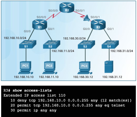
In this example, host 192.168.10.10 has no Telnet connectivity with 192.168.30.12.
- The show access-lists command displays matches for the first deny statement indicating that this ACE has been matched by traffic.
Solution:
- Host 192.168.10.10 has no connectivity with 192.168.30.12 because statement 10 denies host 192.168.10.10, therefore statement 20 can never be matched.
- Statements 10 and 20 should be reversed.
4.4.2.2 – Troubleshooting IPv4 ACLs – Example 2
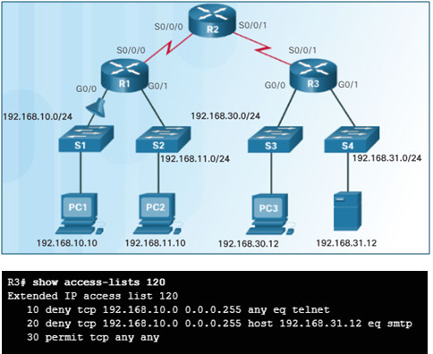
In this example, the 192.168.10.0/24 network cannot use TFTP to connect to the 192.168.30.0/24 network.
Solution:
- Statement 30 in access list 120 allows all TCP traffic.
- However, TFTP uses UDP instead of TCP and therefore it is implicitly denied.
- Statement 30 should be permit ip any any.
4.4.2.3 – Troubleshooting IPv4 ACLs – Example 3
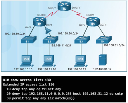
In this example, the 192.168.11.0/24 network can use Telnet to connect to 192.168.30.0/24, but according to company policy, this connection should not be allowed.
The results of the show access-lists 130 command indicate that the permit statement has been matched.
Solution:
- The Telnet port number in statement 10 of ACL 130 is listed in the wrong order as it currently denies any source packet with a port number equal to Telnet.
- Configure 10 deny tcp 192.168.11.0 0.0.0.255 192.168.30.0 0.0.0.255 eq telnet.
4.4.2.4 – Troubleshooting IPv4 ACLs – Example 4
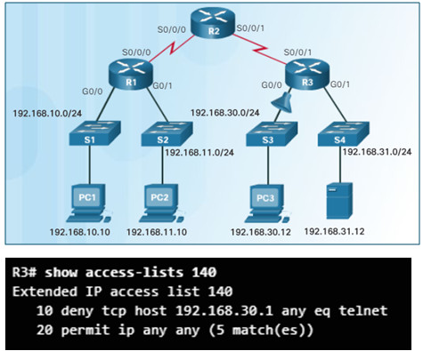
In this example, host 192.168.30.12 is able to Telnet to connect to 192.168.31.12, but company policy states that this connection should not be allowed.
Output from the show access-lists 140 command indicate that the permit statement has been matched.
Solution:
- Host 192.168.30.12 can use Telnet to connect to 192.168.31.12 because there are no rules that deny host 192.168.30.12 or its network as the source.
- Statement 10 of access list 140 denies the router interface on which traffic enters the router.
- The host IPv4 address in statement 10 should be 192.168.30.12.
4.4.2.5 – Troubleshooting IPv4 ACLs – Example 5
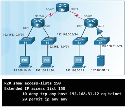
In this example, host 192.168.30.12 can use Telnet to connect to 192.168.31.12, but according to the security policy, this connection should not be allowed.
Output from the show access-lists 150 command indicate that no matches have occurred for the deny statement as expected.
Solution:
- Host 192.168.30.12 can use Telnet to connect to 192.168.31.12 because of the direction in which access list 150 is applied to the G0/1 interface.
- Statement 10 denies any source address to connect to host 192.168.31.12 using Telnet.
- However, this filter should be applied outbound on G0/1 to filter correctly.
4.4.2.6 – Troubleshooting IPv6 ACLs – Example 1
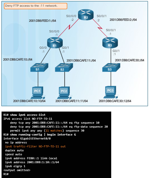
In this example, R1 is configured with an IPv6 ACL to deny FTP access from the :10 network to the :11 network.
- However, after configuring the ACL, PC1 is still able to connect to the FTP server running on PC2.
- The output of the show ipv6 access-list command displays matches for the permit statement but not the deny statements.
Solution:
- The ACL was applied using the correct name, but not the correct direction.
- To correct the issue, remove the ipv6 traffic-filter NO-FTP-TO-11 out and replace it with ipv6 traffic-filter NO-FTP-TO-11 in.
4.4.2.7 – Troubleshooting IPv6 ACLs – Example 2
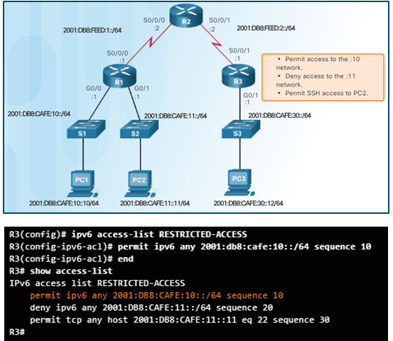
In this example, R3 is configured with an IPv6 ACL named RESTRICTED-ACCESS that should permit access to the :10 network, deny access to the :11 network, and permit SSH access to the PC at 2001:DB8:CAFE:11::11
After configuring the ACL, PC3 cannot reach the 10 or 11 network, and cannot SSH to 2001:DB8:CAFE:11::11.
Solution:
- The first permit statement should allow access to the :10 network but only access to the 2001:DB8:CAFE:10:: host is allowed.
- To correct this issue, remove the host argument and change the prefix to /64. You can do this without removing the ACL by replacing the ACE using the sequence number 10.
- The second error in the ACL is the order of the next two statements therefore remove the statements first, and then enter them in the correct order.
4.4.2.8 – Troubleshooting IPv6 ACLs – Example 3
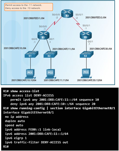
In this example, R1 is configured with an IPv6 ACL named DENY-ACCESS that should permit access to the :11 network from the :30 network, but deny access to the :10 network.
- The DENY-ACCESS ACL is supposed to permit access to the :11 network from the :30 network while denying access to the :10 network.
- However, after applying the ACL to the interface the :10 network is still reachable from the :30 network.
Solution:
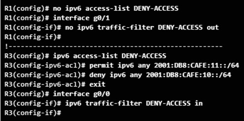
- The problem is with the location of the ACL and should be applied closest to the source of the traffic.
- Remove the ACL on R1 and apply the ACL on R3.
4.4.2.9 – Packet Tracer – Troubleshooting IPv4 ACLs
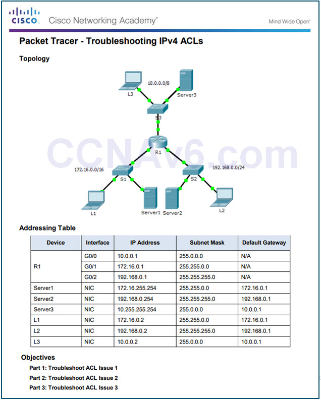
4.4.2.9 Packet Tracer – Troubleshooting IPv4 ACLs
4.4.2.10 – Packet Tracer – Troubleshooting IPv6 ACLs
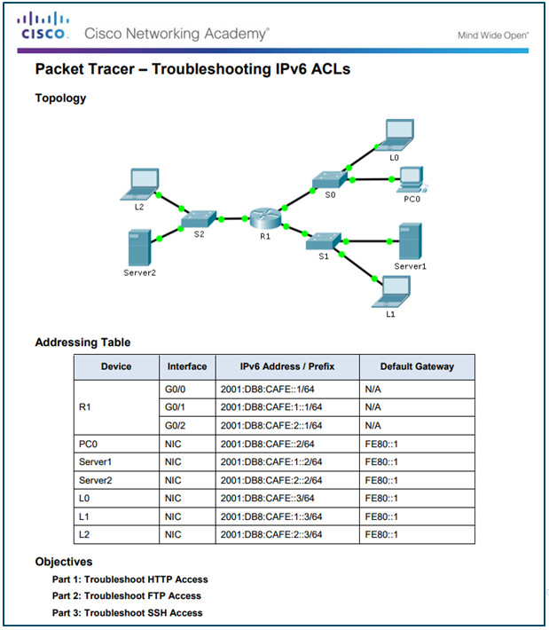
4.4.2.10 Packet Tracer – Troubleshooting IPv6 ACLs
4.4.2.11 – Lab – Troubleshooting ACL Configuration and Placement
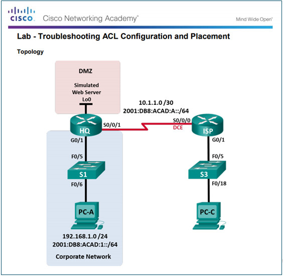
4.4.2.11 Lab – Troubleshooting ACL Configuration and Placement
4.5 – Summary
4.5.1 – Conclusion
4.5.1.1 – Packet Tracer – Skills Integration Challenge
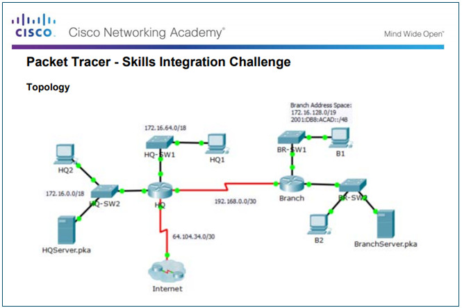
4.5.1.1 Packet Tracer – Skills Integration Challenge
4.5.1.3 – Chapter 4: Access Control Lists
By default a router does not filter traffic. Traffic that enters the router is routed solely based on information within the routing table.
An ACL is a sequential list of permit or deny statements. The last statement of an ACL is always an implicit deny any statement which blocks all traffic. To prevent the implied deny any statement at the end of the ACL from blocking all traffic, the permit ip any any statement can be added.
When network traffic passes through an interface configured with an ACL, the router compares the information within the packet against each entry, in sequential order, to determine if the packet matches one of the statements. If a match is found, the packet is processed accordingly.
ACLs can be applied to inbound traffic or to outbound traffic.
Standard ACLs can be used to permit or deny traffic only from a source IPv4 addresses. The basic rule for placing a standard ACL is to place it close to the destination.
Extended ACLs filter packets based on several attributes: protocol type, source or destination IPv4 address, and source or destination ports. The basic rule for placing an extended ACL is to place it as close to the source as possible.
The access-list global configuration command defines a standard ACL with a number in the range of 1 through 99 or an extended ACL with numbers in the range of 100 to 199. The ip access-list standard name is used to create a standard named ACL, whereas the command ip access-list extended name is for an extended access list.
After an ACL is configured, it is linked to an interface using the ip access-group command in interface configuration mode. A device an only have one ACL per protocol, per direction, per interface.
To remove an ACL from an interface, first enter the no ip access-group command on the interface, and then enter the global no access-list command to remove the entire ACL.
The show running-config and show access-lists commands are used to verify ACL configuration. The show ip interface command is used to verify the ACL on the interface and the direction in which it was applied.
The access-class command configured in line configuration mode is used to link an ACL to a particular VTY line.
From global configuration mode, use the ipv6 access-list name command to create an IPv6 ACL. Unlike IPv4 ACLs, IPv6 ACLs do not use wildcard masks. Instead, the prefix-length is used to indicate how much of an IPv6 source or destination address should be matched.
After an IPv6 ACL is configured, it is linked to an interface using the ipv6 traffic-filter command.
Unlike IPv4, IPv6 ACLs do not have support for a standard or extended option.
