In the previous exercises, we have covered the basics of VLANs and its configuration. As discussed earlier, VLANs are used to separate network traffic, enhance network security, and divide a large network in to several small networks. We know that systems belong to one VLAN cannot communicate to system belong to the other VLANs unless their VLAN name and VLAN IDs do not match. However, there is a method called Inter-VLAN routing that allows different VLANs to communicate to each other. In order to allow Inter-VLAN communication, you need a layer 3 device (router or layer 3 switch). The dot1Q encapsulation is used for the Inter-VLAN communication.
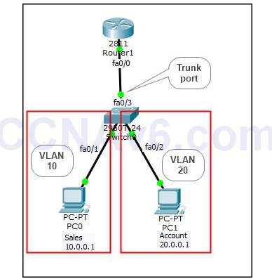
We will use the following topology to demonstrate how to configure Inter-VLAN routing. Also configure IP addresses on both the PCs as mentioned in the topology.

Once you have created the topology and configured IP addresses, next let’s see how to configure Inter-VLAN routing. For this, you need to perform the following configuration.
1. On the switch, execute the following commands to configure appropriate VLANs and assign appropriate interfaces to the respective VLANs.
Switch1( config)# vlan 10
Switch1( config-vlan)# name Sales
Switch1( config-vlan)# exit
2. Once you have configured Sales VLAN, execute the following commands to assign the Fa0/ 1 interface to Sales VLAN.
Switch1( config)# interface fa0/ 1
Switch1( config-if)# switchport mode access
Switch1( config-if)# switchport access vlan 10
Switch1( config-if)# exit
3. Execute the following commands to create another VLAN named Account with the VLAN ID as 20.
Switch1( config)# vlan 20
Switch1( config-vlan)# name Account
Switch1( config-vlan)# exit
4. Once you have created Account VLAN, execute the following commands to assign the Fa0/ 2 interface to Account VLAN.
Switch1( config)# interface fa0/ 2
Switch1( config-if)# switchport mode access
Switch1( config-if)# switchport access vlan 20
Switch1( config-if)# exit
5. Next, execute the following commands to enable VLAN trunking on the Fa0/ 3 interface.
Switch1( config)# interface fa0/ 3
Switch1( config-if)# switchport mode trunk
Switch1( config-if)# exit
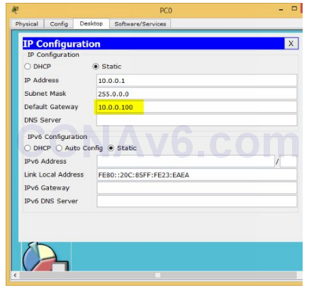
6. After configuring VLANs and VLAN trunking on switch, configure the following TCP/ IP settings on PC0:
- IP address: 10.0.0.1
- Subnet mask: 255.0.0.0
- Default gateway: 10.0.0.100

7. Next, configure the following TCP/ IP settings on PC1:
- IP address: 20.0.0.1
- Subnet mask: 255.0.0.0
- Default gateway: 20.0.0.100
8. Once you have configured appropriate TCP/ IP settings on PC0 and PC1, move to Router. On Router, execute the following command to enable its Fa0/ 0 interface.
Router( config)# interface fa0/ 0
Router( config-if)# no ip address
Router( config-if)# no shutdown
Router( config-if)# exit
9. On Router, execute the following commands to enable the dot1q encapsulation protocol (along with the VLAN ID) and to configure 10.0.0.100/ 8 IP address on its fa0/ 0.10 virtual sub-interface.
Router( config)# interface fa0/ 0.10
Router( config-subif)# encapsulation dot1q 10
Router( config-subif)# ip address 10.0.0.100 255.0.0.0
Router( config-subif)# exit
10. On Router, execute the following commands to enable the dot1q encapsulation protocol (along with the VLAN ID) and to configure 20.0.0.100/ 8 IP address on its fa0/ 0.20 virtual sub-interface.
Router( config)# interface fa0/ 0.20
Router( config-subif)# encapsulation dot1q 20
Router( config-subif)# ip address 20.0.0.100 255.0.0.0
Router( config-subif)# exit
11. Next, execute the following commands to configure the RIP routing (or any other depending on your choice) on Router.
Router( config)# router rip
Router( config-router)# network 10.0.0.0
Router( config-router)# network 20.0.0.0
Router( config)# exit
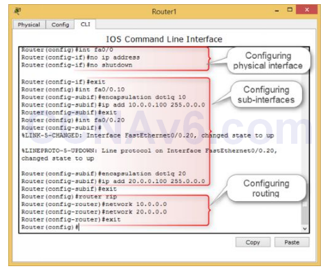
12. The following figure displays the Inter-VLAN configuration on Router.

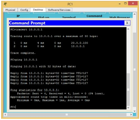
13. That’s all you need to configure for Inter-VLAN routing. Now, it’s time to verify your configuration. To do so, open Command Prompt on PC1, type the following commands to check the connectivity to PC0.
- Tracert 10.0.0.1
- Ping 10.0.0.1
14. You should be able to communicate to PC0 even both the PCs belong to different subnets and VLANs.

