Introduction to VLAN
VLANs are used to segment a large physical LAN into multiple small virtual LANs for better management and greater security. VLANs provide a number advantages and features.
Some of the key features provided by VLANs are:
- VLANs allow to add, move, and change networks with ease by just configuring a port into the appropriate VLAN.
- VLANs allow to create a logical group of users by function.
- VLANs are typically independent from their physical or geographic locations.
- VLANs enhance network security.
- VLANs increase the number of broadcast domains.
Each VLAN is identified by a unique identification number called VLAN ID. The range of VLAN ID can vary from 1-1005. VLAN 1 is the default VLAN (native VLAN) that is used for the administrative purpose.
Cisco manageable switches allows you to configure VLANs as per your network requirements. There are two methods that can be used to configure VLANs.
Static VLAN
An administrator need to configure and update VLAN database manually each time. This method is preferred for a small network.
Dynamic VLAN
VLANs database can be configured and updated with the help of a protocol called VTP (VLAN Trunking Protocol) automatically or with the least user interaction. This method is preferred for the large networks.
VTP Switch Modes
Before configuring the VLANs, we would like to explain the types of VLAN switch modes. A switch can be configured in any of the following three modes:
Server
Switch in this mode can create, modify, and delete VLANs. These VLANs will be updated throughout the VLAN domain.
Transparent
Switch in this mode can also create, modify, and delete VLANs. However, these VLANs will only be applied on the transparent switch (on which the VLANs have been created). Transparent switches pass the VLAN database from one trunk port to another trunk port without compromising the transmitting VLAN database with their own VLAN database.
Client
Switch in this mode cannot create, modify, or delete any VLAN. They can only receive the VLAN database and update their database accordingly.
Configuring VLANs
To configure VLANs on a Cisco switch, use the vlan global configuration command. In addition, one can also use the vlan database command at the privileged mode.
In this exercise, we will configure VLANs on Switch1 and Switch2. The following table lists the details of topology that we will use.
| Switch1 | Switch2 | VLAN ID | VLAN Name |
| PC name: PC0 IP address: 10.0.0.1 Switch interface: Fa0/ 1 |
PC name: PC2 IP address: 10.0.0.3 Interface: Fa0/ 1 |
10 | Sales |
| PC name: PC1 IP address: 10.0.0.2 Switch interface: Fa0/ 2 |
PC name: PC3 IP address: 10.0.0.4 Interface: Fa0/ 2 |
20 | Account |
We will use the following topology to demonstrate how to configure VLANs.
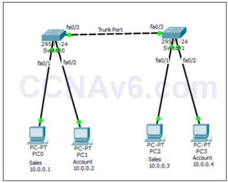
1. Create the preceding topology in Cisco Packet Tracer. Once you have created the preceding topology, configure the appropriate IP addresses on each PCs. After configuring IP addresses, let’s have a look at the command syntaxes used to configure VLANs.
Switch( config)# vlan < vlan number >
Switch( config-vlan)# vlan < name of vlan
2. Once you created the desired VLANs, next you need to assign the interfaces to the desired VLANs. To do so, the following commands are used at the interface configuration mode.
Switch( config-if)# switchport mode access
Switch( config-if)# switchport access vlan < VLAN ID >
Configure VLANs Step By Step
1. Execute the following commands on Switch1 to configure a VLAN named Sales with the VLAN ID as 10.
Switch1( config)# vlan 10
Switch1( config-vlan)# name Sales
Switch1( config-vlan)# exit
2. Execute the following commands on Switch1 to configure a VLAN named Account with the VLAN ID as 20.
Switch1( config)# vlan 20
Switch1( config-vlan)# name Account
Switch1( config-vlan)# exit
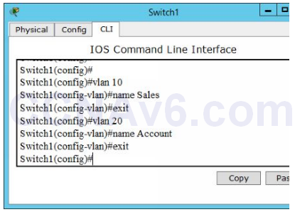
3. The following figure shows how to configure VLANs.
4. Once you have configured the desired VLANs, execute the following commands to assign the Fa0/ 1 interface to Sales VLAN and Fa0/ 2 interface to Account VLAN.
Switch1( config)# interface fa0/ 1
Switch1( config-if)# switchport mode access
Switch1( config-if)# switchport access vlan 10
Switch1( config-if)# exit

Switch1( config)# interface fa0/ 2
Switch1( config-if)# switchport mode access
Switch1( config-if)# switchport access vlan 20
Switch1( config-if)# exit
Switch1( config)# exit
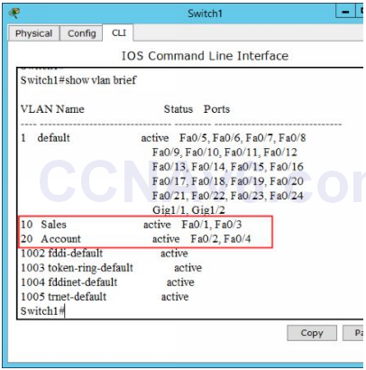
5. Once you have assigned the appropriate interfaces to the appropriate VLANs, verify the VLAN configuration by executing the following command.
Switch1# show vlan brief
6. The following figure shows that the VLANs are configured on Switch1.
7. After configuring VLANs on Switch1, next configure the same VLANs (Sales and Account) and assigned the same interfaces (Fa0/ 1 and fa0/ 2) to the respective VLANs. If you have any issue, refer the above-mentioned table.
Switch( config)# hostname Switch2
Switch2( config)# vlan 10
Switch2( config-vlan)# name Sales
Switch2( config-vlan)# exit
Switch2( config)# vlan 20
Switch2( config-vlan)# name Account
Switch2( config-vlan)# exit

Switch2( config)# interface fa0/ 1
Switch2( config-if)# switchport mode access
Switch2( config-if)# switchport access vlan 10
Switch2( config-if)# exit
Switch2( config)# interface fa0/ 2
Switch2( config-if)# switchport access vlan 20
Switch2( config-if)# exit
Switch2( config)# exit
8. Verify your configuration by executing the following command.
Switch2# show vlan brief
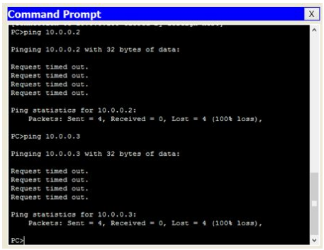
9. Now, you have done the VLAN configurations on both the switches. To verify your VLAN configuration, open Command Prompt on PC0 and type the following command:
Ping 10.0.0.2
10. You should not be able to ping even both the PCs are in the same network. The reason is that PC0 (IP 10.0.0.1, interface Fa0/ 1) and PC1 (IP 10.0.0.2, interface Fa0/ 2) belong to different VLAN IDs.
Ping 10.0.0.3
11. You should not be able to ping, because we still have not configured VLAN trunking (covered in the next section) between both the switches.
Configuring VLAN Trunking
VLAN trunking carries VLAN traffic from switch to another switch using the trunk port. A trunk port is simply a switch port that is used to interconnect switches. In order to forward VLAN traffic from one switch to another switch, you need to enable trunking on the trunk ports of both the switches. To do so, the following command syntaxes are used.
Switch( config-if)# interface < interface name/ number >
Switch( config-if)# switchport mode trunk
In the topology that we have used to configure VLANs, we need to execute the following commands on both the switches.
1. On Switch1, execute the following commands:
Switch1( config-if)# interface Fa0/ 3
Switch1( config-if)# switchport mode trunk
2. On Switch2, execute the following commands:
Switch2( config-if)# interface Fa0/ 3
Switch2( config-if)# switchport mode trunk
3. Verify that the trunking is configured. On Switch1, execute the following command to verify VLAN trunking.
Show interface fa0/ 3 switchport
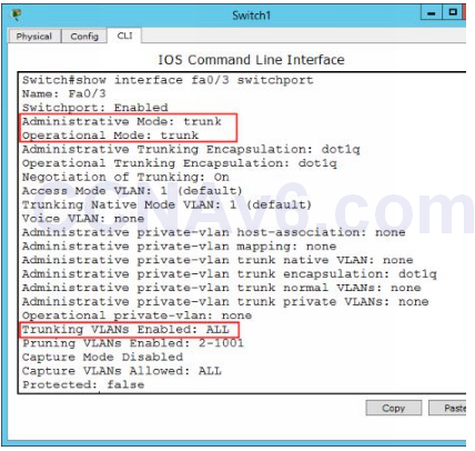
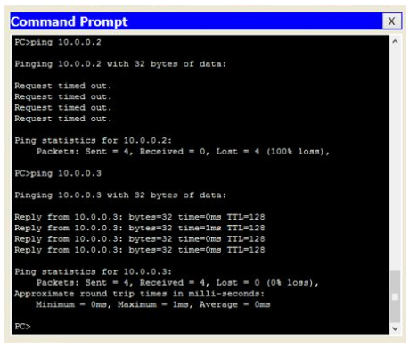
4. Once you have enabled VLAN trunking on the respective ports on the switches, verify your VLAN configuration. To do so, execute the following command on PC0.
- ping 10.0.0.2
5. You should not be able to ping even both the PCs are in the same network. The reason is that PC0 (IP 10.0.0.1, interface Fa0/ 1) and PC1 (IP 10.0.0.2, interface Fa0/ 2) belong to different VLAN IDs.
- ping 10.0.0.3
6. Now you should be able to ping, because we have enabled VLAN trunking between both the switches. Further, PC0 (IP 10.0.0.1, interface Fa0/ 1 of Switch1) and PC2 (IP 10.0.0.3, interface F0/ 1 of Switch2) both belong to the same VLAN ID (Sales 10).
- ping 10.0.0.4
7. You should not be able to ping because PC0 (IP 10.0.0.1, interface Fa0/ 1 of Switch1) and PC3 (IP 10.0.0.4, interface Fa0/ 2 of Switch2) belong to the different VLAN IDs.

I would like to add this command that you missed.
Switch1 # int range fa 0/1 -3
switch port mode truck
Switch2 # int range fa 0/1-3
switchport mode trunk
after this command you can reach all the vlans .
Thank you, i think only trunk f0/3 interface
Admin is right. Only link between switches should be trunk according to theory.