Network loop can create a huge problem in a network. Routing protocols such as RIP and IGRP have their own techniques to stop network loops from occurring at the Network layer of the OSI model. Unfortunately they (routing protocols) cannot be used to stop loops from occurring at the Data Link layer of the OSI model. If you have a network based on layer-2 switches and if the switches are interconnected using the redundant links, your network may suffer from the switching loops. But there is a protocol called Spanning-Tree Protocol (STP) that is used to stop switching loops in a layer-2 switched network.
In this exercise, we will explain how does the spanning-tree protocol work?
STP help a switch to avoid the loop avoidance. It discovers all links in the network andshut down any redundant ones in order to prevent network loops. STP elects a root bridge (switch) on the network through which it passes all the network traffic. The switch with the lowest MAC address becomes the root bridge if the priority of all the switches is set as default which is 32678 plus number of VLANs. However, you can change the priority value of a switch to forcefully make it as a root bridge. Lower value means higher preference in the root bridge election.
The priority value can be any value from 0 through 61440. If you want that a switch should always be the root, set its priority to zero (0). The priority value is set in increments of 4096. If you want to set a switch to be the root bridge for every VLAN in your network, then you have to change the priority for each VLAN.
We will use the following topology to explain the Spanning-Tree Protocol. Create the following topology in Cisco Packet Tracer and connect the switches using the cross-over cables.
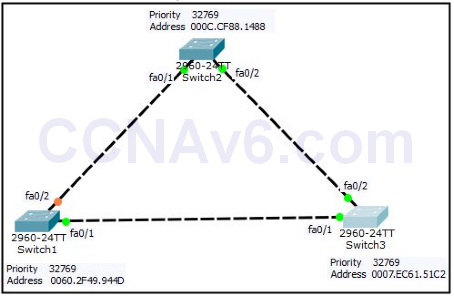
In the preceding topology, first of all, we will find the Root Bridge. On the Root Bridge, you will find “This bridge is the root” message, and the root ID address and bridge ID address will be same.
1. Open the console of Switch1 and execute the show spanning-tree command, as shown in the following figure.
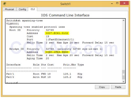
2. In the preceding figure, you can see that Switch1 is not the Root Bridge because the addresses of Root ID and Bridge ID are different.
3. Now, move on Switch2, open the console of Switch2 and execute the show spanning-tree command as shown in the following figure.
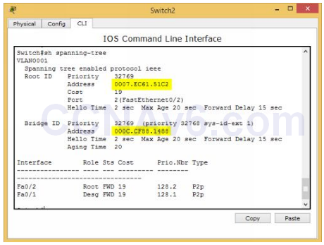
4. In the preceding figure, you can see that Switch2 is also not the Root Bridge because the addresses of Root ID and Bridge ID are different.
5. Now, move on Switch3, open the console of Switch3 and execute the show spanning-tree command as shown in the following figure.
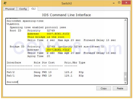
6. In the preceding figure, you can see that Switch2 is the Root Bridge because the addresses of Root ID and Bridge ID are same and it also shows the “This bridge is the root” message.
7. The above selection of Root Bridge was based on MAC addresses because the priority of all the switches has set as default (32769) and the MAC address (Bridge ID) of Switch3 (0007. EC61.51C2) was the lowest among all the switches.
Manual Selection of Root Bridge
As discussed earlier, you can also make a specific switch to act as a Root Bridge by changing its priority value. The following syntax is used to change the priority value of a switch.
Switch( config)# spanning-tree vlan < vlan number > priority < any value from 0 to 61440 but in multiple of 4096 >
1. In the following demonstration, we will make Switch1 as a Root Bridge manually for VLAN 1. To do so, execute the following command.
Switch( config)# spanning-tree vlan 1 priority 8192
Alternatively, you can also use the following command to make a switch as Root Bridge.
Switch( config)# spanning-tree vlan 1 root primary
2. Next, execute the following command to verify the spanning-tree configuration.
Switch# show spanning-tree
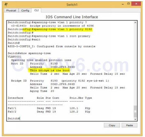
3. In the preceding figure you can see that Switch1 is now the Root Bridge.

Why Switch 1 one port is Alt blocking why not Switch 3