Frame-relay is a WAN technology that supports up to 44.3 Mbps of speed. Nowadays it is not so much popular and heavily replaced by the latest technologies such as ATM. We assume that you know the basics of Frame-relay technology and are familiar with the basic components such as DLCI, LMI, and CIR. If you are not familiar with Frame-relay, we would recommend you to visit the following link to understand the basics of Frame-relay.
Basics of Frame-relay.
Since this guide is focused on the hands-on practical skills, hence we will not cover the theory part of Frame-relay.
Configuring frame-relay is little bit tricky and complicated but not as much as people think. In this exercise, we will explain how to configure frame-relay step by step. For frame-relay configuration, we will create the following topology in Cisco Packet Tracer.
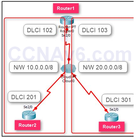
Creating Frame-relay topology is not simple as we created earlier topologies. Hence, we will explain from the most basic so you can create the preceding topology.
First of all, add the routers and a frame-relay switch in Cisco Packet Tracer and interconnect all the devices using the interfaces as mentioned in the preceding topology.
Once you have created the topology, the next step is specify frame-relay interfaces, DLCI, and other parameters. To do so, you need to perform the following steps:
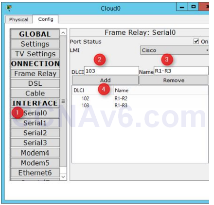
1. Double-click on Cloud0. On the Cloud0 properties dialog box, select Serial0 under INTERFACE.
2. Type 102 in the DLCI field, type R1–R2 in the Name field, and then click Add.
3. Again, type 103 in the DLCI field, type R1–R3 in the Name field, and then click Add.
4. After performing these steps, the Cloud0 properties dialog box should look like the following figure.
5. Next, select Serial1 interface, type 201 in the DLCI field, type R2-R1 in the Name field, and then click Add.
6. Next, select Serial2 interface, type 301 in the DLCI field, type R3-R1 in the Name field, and then click Add.
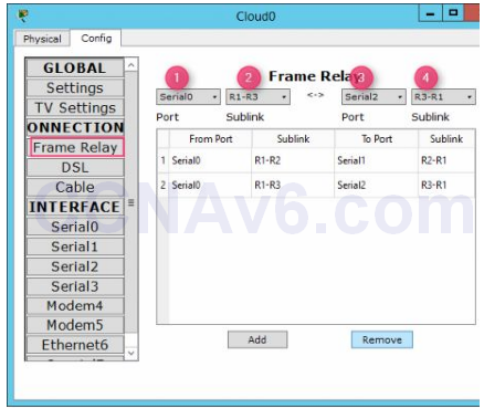
7. Next, select Frame Relay under CONNECTIONS in the left pane.
8. In the right pane, select the values in the following order from the drop-down lists, and then click Add. It will create a frame-relay connection between Router1 and Router3.
A. Serial0
B. R1-R2
C. Serial1
D. R2-R1
9. Again, select the values in the following order from the drop-down lists, and then click Add. It will create a frame-relay connection between Router1 and Router3.
A. Serial 0
B. R1-R3
C. Serial 2
D. R3-R1
10. The following figure to shows how to make the frame-relay connections.
11. Once you have created the frame-relay connections, close the Cloud0 properties dialog box.
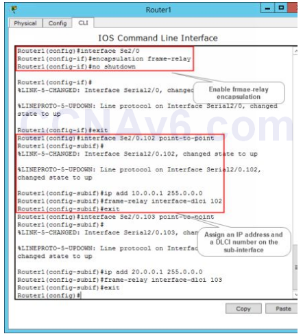
12. Next, move on to Router1 and execute the following commands to enable frame-relay encapsulation on the se2/ 0 interface.
Router1( config)# int se2/ 0
Router1( config-if)# encapsulation frame-relay
Router1( config-if)# no shut
Router1( config-if)# exit
13. Next, execute the following commands to create a point-to-point frame-relay sub-interfaces (one for Router2 and one for Router3), assign an IP addresses, and specify the DLCI numbers.
Router1( config)# int se2/ 0.102 point-to-point
Router1( config-subif)# ip add 10.0.0.1 255.0.0.0
Router1( config-subif)# frame-relay interface-dlci 102
Router1( config-subif)# exit
Router1( config)# int se2/ 0.103 point-to-point
Router1( config-subif)# ip add 20.0.0.1 255.0.0.0
Router1( config-subif)# frame-relay interface-dlci 103
Router1( config-subif)# exit
14. Next, execute the following command to specify a routing method, in this case RIP. However, you may use any other routing method, which feel you more comfortable.
Router1( config)# router rip
Router1( config-router)# network 10.0.0.0
Router1( config-router)# network 20.0.0.0
Router1( config-router)# exit
15. The following figure shows the frame-relay configuration of Router1.
16. After configuring frame-relay on Router1, move on to Router2 and execute the following commands to configure point-to-point frame-relay encapsulation.
Router2( config)# int se2/ 0
Router2( config-if)# ip add 10.0.0.2 255.0.0.0
Router2( config-if)# encapsulation frame-relay
Router2( config-if)# frame-relay interface-dlci 201
Router2( config-if)# no shut
Router2( config-if)# exit
Router2( config)# router rip
Router2( config-router)# network 10.0.0.0
Router2( config-router)# exit
17. After configuring frame-relay on Router1 and Router2, move on to Router3 and execute the following commands to configure point-to-point frame-relay encapsulation.
Router3( config)# int se2/ 0
Router3( config-if)# ip add 20.0.0.2 255.0.0.0
Router3( config-if)# encapsulation frame-relay
Router3( config-if)# frame-relay interface-dlci 301
Router3( config-if)# no shut
Router3( config-if)# exit
Router3( config)# router rip
Router3( config-router)# network 20.0.0.0
Router3( config-router)# exit
18. Now, you have configured point-to-point frame-relay encapsulation on all the routers. Next, verify your frame-relay configuration. To do so, execute the following commands on Router3 and examine the output of each command.
Router3# show frame-relay pvc
Router3# show frame-relay map
Router3# ping 10.0.0.2
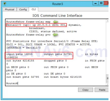
19. In the preceding figure, you can see that frame-relay encapsulation has been configured on the Serial2/ 0 interface of Router3.
In this exercise, you have learned how to configure point-to-point point-to-point frame-relay encapsulation.
