Network Address Translation (NAT) technique translates private IP addresses into public IP addresses. NAT enhances the security of the network by hiding the actual IP information from the external users. The external users see the translated IP addresses rather than actual IP addresses. This is also called masking. There are two types of NAT: Static NAT and Dynamic NAT.
The Static NAT is useful for a small number of users where an administrator can manually create a MAP table of Public and Private IP addresses. However, for a large network where the number of users are in hundreds and thousands, it is not possible or at least a difficult task to create a MAP table manually. Here, you can use Dynamic NAT that allows you to define a range of public IP addresses that will be translated. When the internal users (inside network) try to access external resources (outside network), the NAT router replaces its private IP address with the available Public IP address from the configured range.
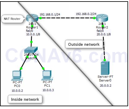
We will use the following topology to demonstrate how to configure NAT. Create the following topology in Cisco Packet Tracer.

After creating the preceding topology, configure the appropriate IP addresses on the devices mentioned in the topology. In addition, you also need to perform a routing algorithm. You can use any of the routing algorithms depending on your choice. So before proceed to next prepare your topology.
Configure Static NAT
To configure NAT, you need to perform the following steps:
1. On Router1, execute the following command to specify the inside interface that is Fa0/ 0.
Router1( config)# int fa0/ 0
Router1( config-if)# ip nat inside
Router1( config-if)# exit
2. Next, execute the following command to specify the outside interface that is Fa0/ 1.
Router1( config)# int fa0/ 1
Router1( config-if)# ip nat outside
Router1( config-if)# exit
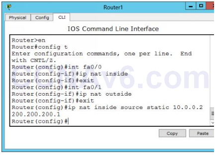
3. Once you have defined the inside and outside interfaces, now you need to specify the private IP addresses that need to be translated into the public IP addresses. In this demonstration, we will translate 10.0.0.2 private IP address into the 200.200.200.1 public IP address. To do so, execute the following command.
Router1( config)# ip nat inside source static 10.0.0.2 200.200.200.1
Router1( config)# exit
4. The following figure shows how to configure static NAT on a router.

5. Once you have configured static NAT, now it’s time to verify your configuration. To verify the static NAT configuration, start a communication process between inside and outside networks. For this, open the Command Prompt window on PC0 and type ping 20.0.0.2. Leave the Command Prompt active and move on to Router1.
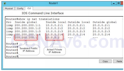
6. On Router1, type the following command to view the NAT translation table.
Router1# show ip nat translations

7. In the preceding figure, you can see that 10.0.0.2 private IP address has been translated into 200.200.200.1 public IP address. That’s what does NAT actually.
Removing NAT Configuration
If you have mapped a wrong IP address or want to disable the NAT translation for any reason, execute the following command.
Router1( config)# no ip nat inside source static 10.0.0.2 200.200.200.1
Now, your topology is ready to perform the next exercise “configure dynamic NAT”. If you have doubts on topology, better to reload the topology and re-configure the IP addresses and routing method.
Configure Dynamic NAT
As discussed earlier, dynamic NAT is used for a large network or when a large number of users want to access external resources. Configuring dynamic NAT is slightly different from the static NAT. In dynamic NAT, you need to apply an ACL to specify which users or networks are allowed to access external resources and need to be translated. After that you need to create a Range of IP addresses (pool) from which the NAT router will allocate the IP addresses to internal users on the first come first serve basis.
To configure dynamic NAT, you need to perform the following steps:
1. On Router1, execute the following commands to specify the inside and outside interfaces.
Router1( config)# int fa0/ 0
Router1( config-if)# ip nat inside
Router1( config-if)# exit
Router1( config)# int fa0/ 1
Router1( config-if)# ip nat outside
Router1( config-if)# exit
2. Now, execute the following command to create a pool and specify the ranges that the NAT router will use to allocate IP addresses.
Router1( config)# ip nat pool mypool 150.150.1.1 150.150.1.10 netmask 255.255.0.0
3. Next, execute the following command to apply the created pool.
Router1( config)# ip nat inside source list 10 pool mypool
4. Next, execute the following commands to apply an ACL to allow the networks.
Router1( config)# access-list 10 permit 10.0.0.0 0.255.255.255
5. Next, execute the following command to specify the interface and the ACL direction.
Router1( config)# int fa0/ 0
6. Router1( config-if)# ip access-group 50 out
Router1( config-if)# exit
Router1( config)# exit
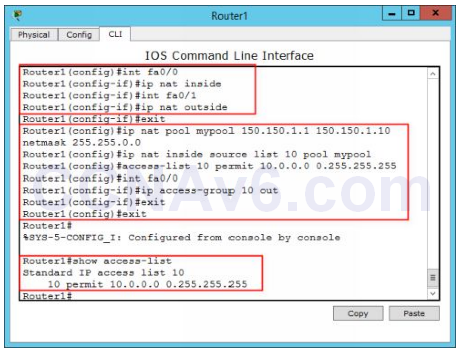
7. The following figure shows the Dynamic NAT configuration on Router1.

Verify Dynamic NAT configuration
1. To verify dynamic NAT configuration, open command prompts on PC0 and PC1 and type the following command on both PCs:
Ping 192.168.1.2
2. Now, execute the following command to show the translated IP addresses.
Router1# show ip nat translations
3. Close the Cisco Packet Tracer.

I’m unable to ping server after configuring NAT. Can anyone help regarding this `
You have to configured that two router and activate it