Instructor Planning Guide
Activities
What activities are associated with this chapter?
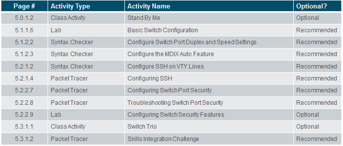
Assessment
Students should complete Chapter 5, “Assessment” after completing Chapter 5.
Quizzes, labs, Packet Tracers and other activities can be used to informally assess student progress.
Sections & Objectives
5.1 Basic Switch Configuration
Configure basic switch settings to meet network requirements.
Configure initial settings on a Cisco switch.
Configure switch ports to meet network requirements.
5.2 Basic Device Configuration
Configure a switch using security best practices in a small to medium-sized business network.
Configure the management virtual interface on a switch.
Configure the port security feature to restrict network access.
Chapter 5: Switch Configuration
5.1 – Basic Switch Configuration
5.1.1 – Configure a Switch with Initial Settings
5.1.1.1 – Switch Boot Sequence
When a switch is powered on, the boot sequence occurs.
- Power-on self-test (POST), a program stored in ROM, executes and checks hardware like CPU and RAM.
- The boot loader, also stored in ROM, runs and initializes parts within the CPU, initializes the flash file system, and then locates and loads an IOS image.
- The IOS image can be defined within the BOOT environment variable.
- If the variable is not set, the switch scours through the flash file system searching for an executable image file, loading it into RAM, and launching it if found.
- If an executable image file is not found, the switch shows the prompt switch: where a few commands are allowed in order to provide access to operating system files found in flash memory and files used to load or reload an operating system.
- If an IOS operating system loads, the switch interfaces are initialized and any commands stored in the startup-config file load.
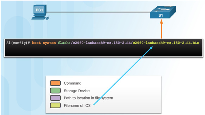
The boot system command is use to set the BOOT environment variable.
5.1.1.2 – Recovering From a System Crash
The boot loader prompt can be accessed through a console connection to the switch:
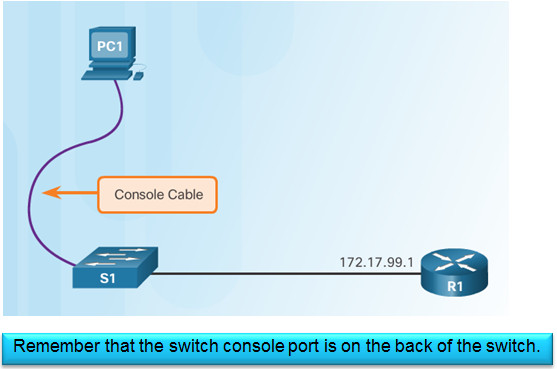
- Cable the PC to the switch console port.
- Configure the terminal emulation software on the PC.
- Unplug the switch power cord.
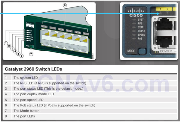
- Reconnect the power cord and at the same time or within 15 seconds, press and hold the Mode button on the front of the switch until the System LED turns an amber color briefly and then turns a solid green.
The boot loader command prompt is switch: (instead of Switch>).
- The commands available through the boot loader command prompt are limited.
- Use the help command to display the available commands.

5.1.1.3 – Switch LED Indicators
System LED shows if the switch has power applied.
Port LED states:
- Off – no link or shut down
- Green – link is present
- Blinking green – data activity
- Alternating green and amber – link fault
- Amber – port is not sending data; common for first 30 seconds of connectivity or activation
- Blinking amber – port is blocking to prevent a switch loop
5.1.1.4 – Preparing for Basic Switch Management
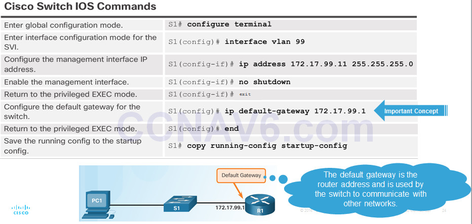
To configure a switch for remote access, the switch must be configured with an IP address, subnet mask, and default gateway.
One particular switch virtual interface (SVI) is used to manage the switch:
- A switch IP address is assigned to an SVI.
- By default the management SVI is controlled and configured through VLAN 1.
- The management SVI is commonly called the management VLAN.
For security reasons, it is best practice to use a VLAN other than VLAN 1 for the management VLAN.
5.1.1.5 – Configuring Basic Switch Management Access with IPv4
5.1.1.6 – Lab – Basic Switch Configuration
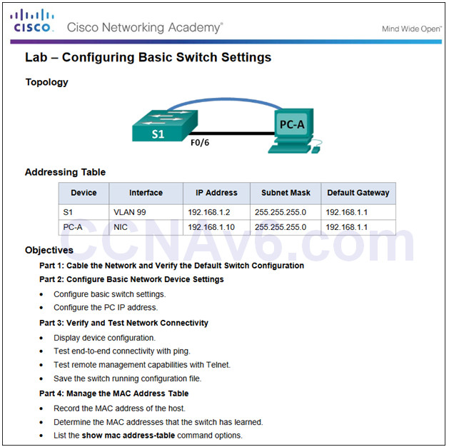
5.1.1.6 Lab – Configuring Basic Switch Settings
5.1.2 – Configure Switch Ports
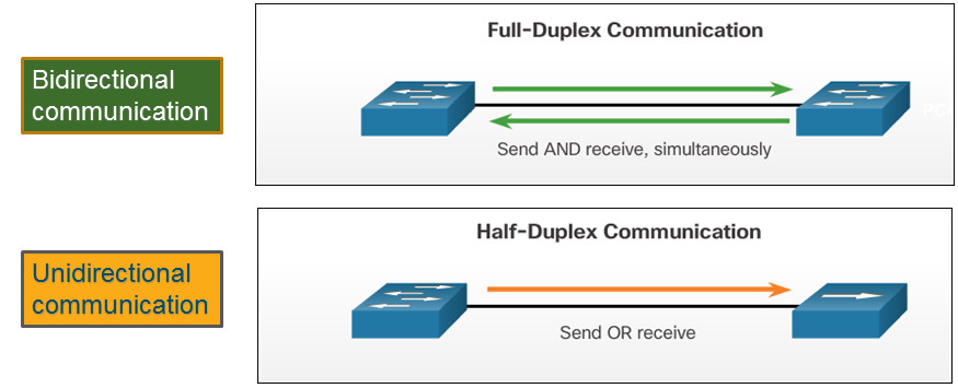
5.1.2.1 – Duplex Communication
Gigabit Ethernet and 10Gb Ethernet NICs require full-duplex connections to operate.
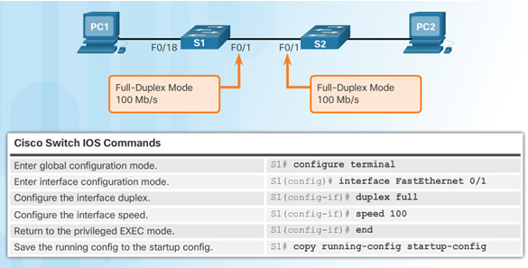
5.1.2.2 – Configure Switch Ports at the Physical Layer
Some switches have the default setting of auto for both duplex and speed.
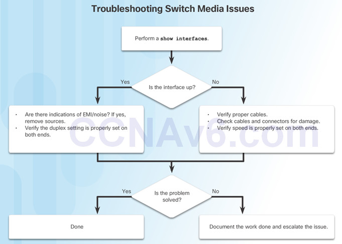
Mismatched duplex and/or speed settings can cause connectivity issues.
Always check duplex and speed settings using the show interface interface_id command.
All fiber ports operate at one speed and are always full-duplex.
5.1.2.3 – Auto-MDIX
Some switches have the automatic medium-dependent interface crossover (auto-MDIX) feature that allows an interface to detect the required cable connection type (straight-through or crossover) and configure the connection appropriately.
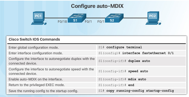
Use the show controllers Ethernet-controller command to verify auto-MDIX settings.

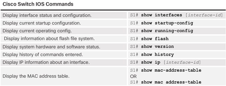
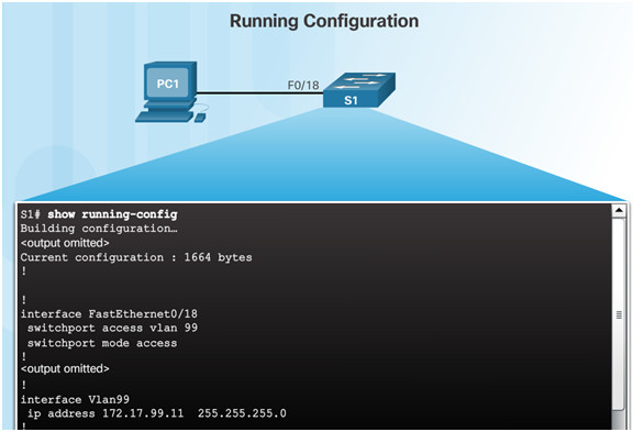
5.1.2.4– Verifying Switch Port Configuration
5.1.2.5 – Network Access Layer Issues
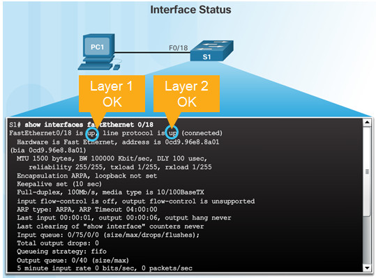
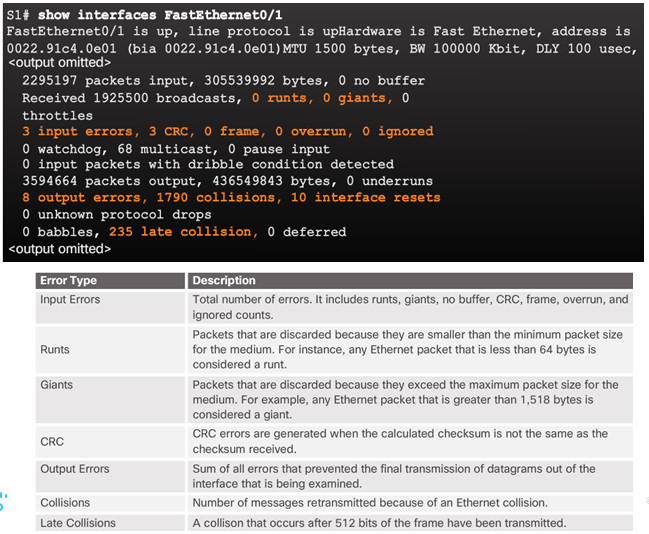
Use the show interfaces command to detect common media issues.
The first parameter refers to Layer 1, the physical layer, and indicates if the interface is receiving a carrier detect signal.
The second parameter (protocol status) refers to the data link layer and indicates whether the data link layer protocol has been configured correctly and keepalives are being received.

5.1.2.6– Troubleshooting Network Access Layer Issues
5.2 – Switch Security
5.2.1 – Secure Remote Access
5.2.1.1 – SSH Operation
Secure Shell (SSH)
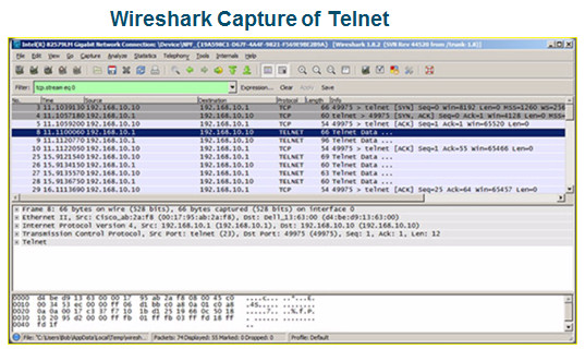
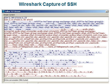
- An alternative protocol to Telnet. Telnet uses unsecure plaintext of the username and password as well as the data transmitted.
- SSH is more secure because it provides an encrypted management connection.
A switch must have an IOS version (k9 at the end of the IOS file name) that includes cryptographic capabilities in order to configure and use SSH.
Use the show version command to see the IOS version.

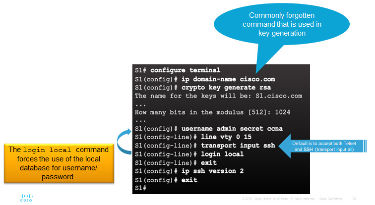
5.2.1.2 – Configuring SSH
1.Verify SSH support.
2.Configure the IP domain name.
3.Generate RSA key pairs.
4.Configure user authentication.
5.Configure the vty lines.
6.Enable SSH version 2.
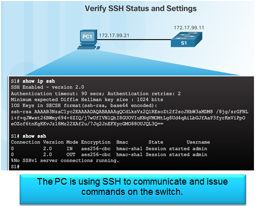
5.2.1.3 – Verifying SSH
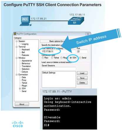
On the PC, connect to the switch using SSH.
5.2.1.4 – Packet Tracer – Configuring SSH
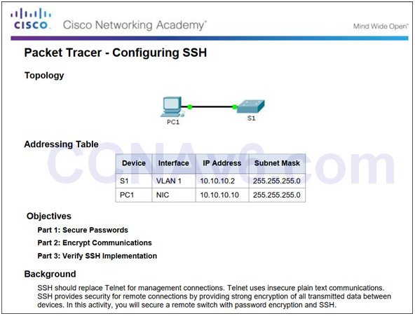
5.2.1.4 Packet Tracer – Configuring SSH
5.2.2 – Switch Port Security
5.2.2.1 – Secure Unused Ports
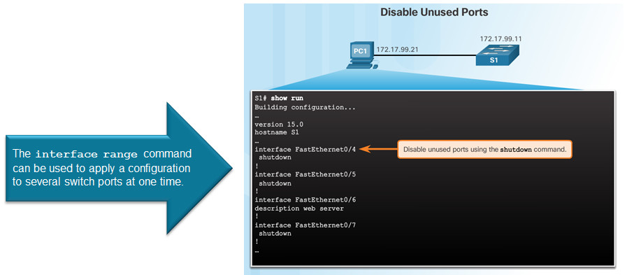
5.2.2.2 – Port Security: Operation
Port security limits the number of valid MAC addresses allowed to transmit data through a switch port.
- If a port has port security enabled and an unknown MAC address sends data, the switch presents a security violation.
- Default number of secure MAC addresses allowed is 1.
Methods use to configure MAC addresses within port security:
- Static secure MAC addresses – manually configure
switchport port-security mac-address mac-address
- Dynamic secure MAC addresses – dynamically learned and removed if the switch restarts
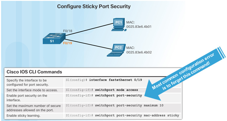
- Sticky secure MAC addresses – dynamically learned and added to the running configuration (which can later be saved to the startup-config to permanently retain the MAC addresses)
switchport port-security mac-address sticky mac-address
Note: Disabling sticky learning converts sticky MAC addresses to dynamic secure addresses and removes them from the running-config.
5.2.2.3 – Port Security: Violation Modes
Protect – data from unknown source MAC addresses are dropped; a security notification IS NOT presented by the switch
Restrict – data from unknown source MAC addresses are dropped; a security notification IS presented by the switch and the violation counter increments.
Shutdown – (default mode) interface becomes error-disabled and port LED turns off. The violation counter increments. Issues the shutdown and then the no shutdown command on the interface to bring it out of the error-disabled state.

5.2.2.4 – Port Security: Configuring

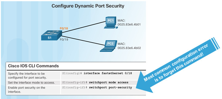
Before configuring port-security features, place the port in access mode and use the switchport port-security interface configuration command to enable port security on an interface.
5.2.2.5 – Port Security: Verifying
Use the show port-security interface command to verify the maximum number of MAC addresses allowed on a particular port and how many of those addresses were learned dynamically using sticky.

Use the show running-config command to see learned MAC addresses added to the configuration.

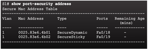
The show port-security address command shows how MAC addresses were learned on a particular port.
5.2.2.6 – Ports in Error Disabled State
Switch console messages display when a port security violation occurs. Notice the port link status changes to down.

Check the port status and the port security settings.
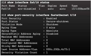
Do not re-enable a port until the security threat is investigated and eliminated.
Notice that you must first shut the port down and then issue the no shutdown command in order to use the particular port again after a security violation has occurred.

5.2.2.7 – Packet Tracer – Configuring Switch Port Security
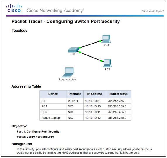
5.2.2.7 Packet Tracer – Configuring Switch Port Security
5.2.2.8 – Packet Tracer – Troubleshooting Switch Port Security
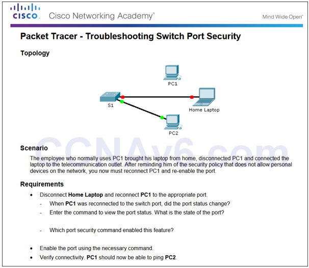
5.2.2.8 Packet Tracer – Troubleshooting Switch Port Security
5.2.2.9 – Lab – Configuring Switch Security Features
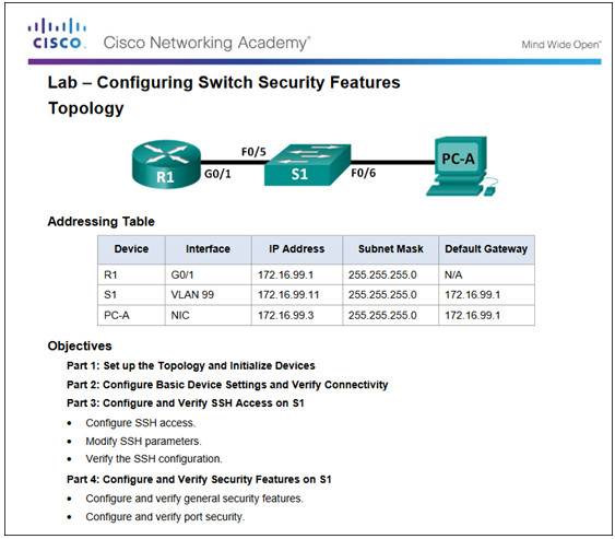
5.2.2.9 Lab – Configuring Switch Security Features
5.3 – Summary
5.3.1 – Conclusion
5.3.1.1 Switch Trio Instructions
5.3.1.1 Switch Trio Instructions
5.3.1.2 – Packet Tracer – Skills Integration Challenge
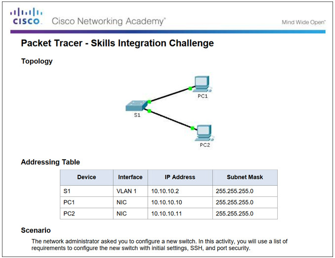
5.3.1.2 Packet Tracer – Skills Integration Challenge
5.3.1.3 – Switch Configuration
Configure basic switch settings to meet network requirements.
Configure a switch using security best practices in a small to medium-sized business network.
New Terms and Commands
| •POST
•Boot loader •boot system command •show boot command •switch: prompt •Mode button •System LED •Port LED •SVI •VLAN •Management VLAN •interface vlan command •vlan command •name command |
•Full-duplex
•Half-duplex •Port speed •duplex command •speed command •mdix command •show interfaces command •SSH configuration •ip domain-name command •crypto key generate rsa command •transport input local command •username secret command •ip ssh version 2 command |
•login local command
•show ip ssh command •Unused ports •Port security •switchport mode access command •switchport port-security command •switchport port-security maximum command •switchport port-security mac-address sticky command •show port-security interface command •show port-security address command |
