4.1.6 Packet Tracer – UDP and TCP Port Numbers Answers
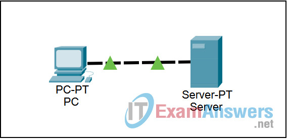
Topology

Learning Objectives
- Setup and run the simulation
- Examine the results
Introduction:
UDP and TCP are TCP/IP Protocols that correspond to OSI Layer 4, the Transport layer. The PDUs for UDP and TCP differ substantially, but they share the notion of port numbers. Segments contain port numbers that identify the service the client is requesting from the server and port numbers generated by the client to which the server should reply. In addition to port numbers, the TCP segment also contains sequence numbers. Sequence numbers provide reliability by identifying missing segments and allowing the reassembly of the application data by putting the segments back together in the proper order.
Task 1: Setup and run the simulation
Step 1. Enter simulation mode
Click the Simulation tab to enter simulation mode.
Step 2. Set Event List Filters
We want to capture only DNS and HTTP events. In the Event List Filters section, click the Edit Filters button and make sure only DNS and HTTP events are selected.
Step 3. From the PC, request a web page from the Server
Click on the PC in the logical workplace. Open the Web Browser on the Desktop. Type udptcpexample.com into the URL box and click the Go button. Minimize the simulated browser window.
Step 4. Run the simulation
Click the Auto Capture / Play button. The exchange between the PC and the server is animated and the events are added to the Event List. These events represent the client PC’s request for DNS service, followed by the request for a web page. The server sends the web page in two segments, and the PC acknowledges the web page. A dialog box appears indicating there are no more events to be captured. Click OK to close it.
Task 2: Examine the results
Step 1. Access specific PDUs
In the Simulation Panel Event List section, the last column contains a colored box that provides access to detailed information about an event. Click the colored box in the last column for the first event. The PDU Information window opens.
Step 2. Examine the contents of the PDU Information Window
In this activity, we will focus only on event information only at Layers 4 and 7. The first tab in the PDU Information window contains information about the inbound and outbound PDU as it relates to the OSI model. Click the Layer 4: and Layer 7: boxes for both the inbound and outbound layers and read the content of the box and description in the box below the layers. Note that DNS uses UDP and HTTP uses TCP.
Pay attention to the port numbers. Port 53 represents DNS, the application protocol that associates domain names with IP addresses. Port 80 represents HTTP the application protocol that supports web pages. The other port is generated by the client PC from the range of port numbers greater than 1023. Click the Outbound PDU Details tab. In the TCP segment, note the initial sequence number.
Examine the PDU information for the other events in the same fashion. Note the change to the source and destination port numbers (for both UDP and TCP) and the change in the sequence number (for TCP only) as the next segment is delivered.
Note that if you use the Reset Simulation button, you must also return to the browser window and press Enter again to re-issue the web page request. This will allow you to re-capture and animate the DNS and HTTP-generated packets.
