5.3.3.2 Lab – Troubleshoot LAN Traffic Using SPAN (Instructor Version)
Instructor Note: Red font color or gray highlights indicate text that appears in the instructor copy only.
Topology
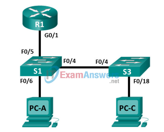
Addressing Table
| Device | Interface | IP Address | Subnet Mask | Default Gateway |
|---|---|---|---|---|
| R1 | G0/1 | 192.168.1.1 | 255.255.255.0 | N/A |
| S1 | VLAN 1 | 192.168.1.2 | 255.255.255.0 | 192.168.1.1 |
| S3 | VLAN 1 | 192.168.1.3 | 255.255.255.0 | 192.168.1.1 |
| PC-A | NIC | 192.168.1.254 | 255.255.255.0 | 192.168.1.1 |
| PC-C | NIC | 192.168.1.10 | 255.255.255.0 | 192.168.1.1 |
Objectives
Part 1: Build the Network and Verify Connectivity
Part 2: Configure Local SPAN and Capture Copied Traffic with Wireshark
Background / Scenario
As the network administrator you decide to analyze the internal local area network for suspicious network traffic and possible DoS or reconnaissance attacks. To do this, you will set up port mirroring on all active switchports and mirror/copy all traffic to a designated switch port where a PC running Wireshark can analyze the captured traffic. The goal is to identify the source of suspicious traffic. To set up port mirroring you will use the Switched Port Analyzer (SPAN) feature on the Cisco switch. It is common to find a device running a packet sniffer or Intrusion Detection System (IDS) connected to the mirrored port.
Note: The routers used with CCNA hands-on labs are Cisco 1941 Integrated Services Routers (ISRs) with Cisco IOS Release 15.4(3) (universalk9 image). The switches used are Cisco Catalyst 2960s with Cisco IOS Release 15.0(2) (lanbasek9 image). Other routers, switches, and Cisco IOS versions can be used. Depending on the model and Cisco IOS version, the commands available and output produced might vary from what is shown in the labs. Refer to the Router Interface Summary Table at the end of this lab for the correct interface identifiers.
Note: Make sure that the routers and switches have been erased and have no startup configurations. If you are unsure, contact your instructor.
Instructor Note: Refer to the Instructor Lab Manual for the procedures to initialize and reload devices.
Required Resources
- 1 Router (Cisco 1941 with Cisco IOS Release 15.4(3) universal image or comparable)
- 2 Switches (Cisco 2960 with Cisco IOS Release 15.0(2) lanbasek9 image or comparable)
- 2 PCs (Windows with a terminal emulation program, such as Tera Term or PuTTY, Wireshark, and Zenmap)
- Console cables to configure the Cisco IOS devices via the console ports
- Ethernet and serial cables as shown in the topology
Part 1: Build the Network and Verify Connectivity
In Part 1, you will set up the network topology and configure basic settings, such as the interface IP addresses, static routing, device access, and passwords.
Step 1: Cable the network as shown in the topology.
Attach the devices as shown in the topology diagram, and cable as necessary.
Step 2: Configure PC hosts.
Step 3: Initialize and reload the routers and switches as necessary.
Step 4: Configure basic settings for the router.
a. Disable DNS lookup.
b. Configure the device name as shown in the topology.
c. Configure an IP address for the router as listed in the Addressing Table.
d. Assign class as the encrypted privileged EXEC mode password.
e. Assign cisco for the console and vty password, enable login.
f. Set the vty lines to transport input telnet
g. Configure logging synchronous to prevent console messages from interrupting command entry.
h. Copy the running configuration to the startup configuration.
Step 5: Configure basic settings for each switch.
a. Disable DNS lookup.
b. Configure the device name as shown in the topology.
c. Assign class as the encrypted privileged EXEC mode password.
d. Configure IP addresses for the switches as listed in the Addressing Table.
e. Configure the default gateway on each switch.
f. Assign cisco for the console and vty password and enable login.
g. Configure logging synchronous to prevent console messages from interrupting command entry.
h. Copy the running configuration to the startup configuration.
Step 6: Verify connectivity.
a. From PC-A, you should be able to ping the interface on R1, S1, S3, and PC-C. Were all pings successful?
____________Yes
If the pings are not successful, troubleshoot the basic device configurations before continuing.
b. From PC-C, you should be able to ping the interface on R1, S1, S3, and PC-A. Were all pings successful?
___________Yes
If the pings are not successful, troubleshoot the basic device configurations before continuing.
Part 2: Configure Local SPAN and Capture Copied Traffic with Wireshark
To configure Local SPAN, you need to configure one or more source ports called monitored ports, and a single destination port, also called a monitored port, for copied or mirrored traffic to be sent out of. SPAN source ports can be configured to monitor traffic in either ingress, or egress, or both directions (default).
Step 1: Configure SPAN on S1.
a. Locate the switchports that are up on S1
S1# show ip interface brief
Which switchports are physically up and logically up? __________________________________
F0/4, F0/5, F0/6 are up
b. On S1, F0/6 connects to PC-A which will be used for analyzing traffic with Wireshark. F0/6 will be the SPAN destination monitor port for duplicated packets. F0/4 and F0/5 will be the source monitor ports for intercepted packets. You can configure multiple source monitor ports but only one destination monitor port.
S1(config)# monitor session 1 source interface f0/4 - 5
S1(config)# monitor session 1 destination interface f0/6
Step 2: Start a Wireshark Capture on PC-A.
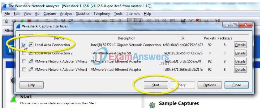
a. Open Wireshark on PC-A, set the capture interface to the Local Area Connection and click Start.
Step 3: From PC-C, Use NMAP to Generate Suspicious Traffic.
a. If necessary, navigate to NMAP.org to download Zenmap. Scroll down the page to find the latest stable release for PC-C. Then following the on-screen instructions to install Zenmap with default settings.
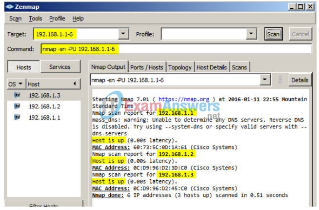
b. Open Zenmap on PC-C and run a UDP ping scan to scan for available hosts (nmap –sn –PU 192.168.1- 6). The scan result identifies 3 hosts on the network R1, S1, and S2 at 192.168.1.1, 192.168.1.2 and 192.168.1.3. Notice that Zenmap has also identified the MAC addresses of the three hosts as Cisco Systems interfaces. If this were a real network reconnaissance attack the scan might involve the entire range of network hosts as well as ports and OS fingerprinting.
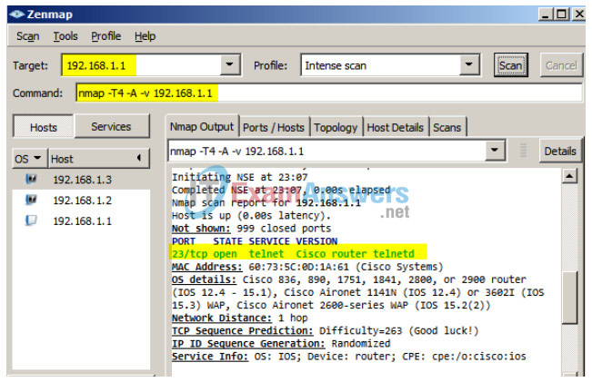
c. The hypothetical attacker can now issue an intense scan on R1 at 192.168.1.1 (nmap –T4 –A –v 192.168.1.1). The scan result identifies an open port 23/Telnet.
Step 4: From PC-A Stop the Wireshark Capture and Examine the Captured SPAN Packets.
a. Return to PC-A, and stop the Wireshark capture. Notice the non-standard traffic patterns between PC-C at 192.168.1.10 and R1 at 192.168.1.1. It is filled with Out-Of-Order segments and Connection resets (RST). This packet capture identifies PC-C as sending suspicious traffic to router R1.
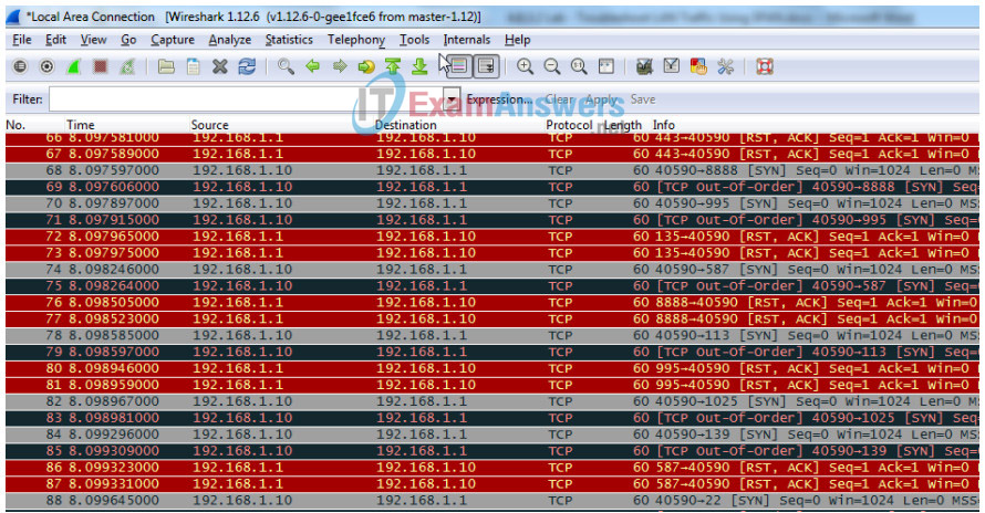
b. The attacker on PC-C knowing that the router has an open port on 23 could attempt an additional brute force attack or DoS style attack, like a LAND attack. A LAND attack is a TCP SYN packet with the same source and destination IP address and port number. Using Zenmap, the command nmap –sS 192.168.1.1 –S 192.168.1.1 –p23 –g23 –e eth0 is an example. Notice how the LAND attack sets both the source and destination IP addresses to 192.168.1.1 and both the source and destination port numbers to the open port at 23. Although R1 with IOS15 is not vulnerable to this older type of DoS attack, many older systems and servers are still vulnerable. This attack will crash vulnerable systems, by setting them into an infinite loop.
Reflection
In this scenario, SPAN was used to troubleshoot and identify the source of suspicious activity on the network? What other troubleshooting scenarios might SPAN be useful for?
________________________________________________________
Answers will vary. Examples: Identifying the source of excessive broadcasts on the network. Identifying hosts infected with malware that attempt to call out to command and control servers, etc.
Router Interface Summary Table
| Router Interface Summary | ||||
|---|---|---|---|---|
| Router Model | Ethernet Interface #1 | Ethernet Interface #2 | Serial Interface #1 | Serial Interface #2 |
| 1800 | Fast Ethernet 0/0 (F0/0) | Fast Ethernet 0/1 (F0/1) | Serial 0/0/0 (S0/0/0) | Serial 0/0/1 (S0/0/1) |
| 1900 | Gigabit Ethernet 0/0 (G0/0) | Gigabit Ethernet 0/1 (G0/1) | Serial 0/0/0 (S0/0/0) | Serial 0/0/1 (S0/0/1) |
| 2801 | Fast Ethernet 0/0 (F0/0) | Fast Ethernet 0/1 (F0/1) | Serial 0/1/0 (S0/1/0) | Serial 0/1/1 (S0/1/1) |
| 2811 | Fast Ethernet 0/0 (F0/0) | Fast Ethernet 0/1 (F0/1) | Serial 0/0/0 (S0/0/0) | Serial 0/0/1 (S0/0/1) |
| 2900 | Gigabit Ethernet 0/0 (G0/0) | Gigabit Ethernet 0/1 (G0/1) | Serial 0/0/0 (S0/0/0) | Serial 0/0/1 (S0/0/1) |
| Note: To find out how the router is configured, look at the interfaces to identify the type of router and how many interfaces the router has. There is no way to effectively list all the combinations of configurations for each router class. This table includes identifiers for the possible combinations of Ethernet and Serial interfaces in the device. The table does not include any other type of interface, even though a specific router may contain one. An example of this might be an ISDN BRI interface. The string in parenthesis is the legal abbreviation that can be used in Cisco IOS commands to represent the interface. | ||||
Device Configs
Router R1
R1#show run
Building configuration...

Current configuration : 1379 bytes
!
version 15.4
service timestamps debug datetime msec
service timestamps log datetime msec
no service password-encryption
!
hostname R1
!
boot-start-marker
boot-end-marker
!
!
enable secret 5 $1$9VIJ$vAdKomdXQ9N4SieMoFxeD1
!
no aaa new-model
!
!
no ip domain lookup
ip cef
no ipv6 cef
!
multilink bundle-name authenticated
!
cts logging verbose
!
!
license udi pid CISCO1941/K9 sn FTX163283RA
license accept end user agreement
license boot module c1900 technology-package securityk9
!
!
redundancy
!
!
interface Embedded-Service-Engine0/0
no ip address
shutdown
!
interface GigabitEthernet0/0
no ip address
shutdown
duplex auto
speed auto
!
interface GigabitEthernet0/1
ip address 192.168.1.1 255.255.255.0
duplex auto
speed auto
!
interface Serial0/0/0
no ip address
shutdown
clock rate 2000000
!
interface Serial0/0/1
no ip address
shutdown
!
ip forward-protocol nd
!
no ip http server
no ip http secure-server
!
control-plane
!
!
line con 0
password cisco
logging synchronous
login
line aux 0
line 2
no activation-character
no exec
transport preferred none
transport output pad telnet rlogin lapb-ta mop udptn v120 ssh
stopbits 1
line vty 0 4
password cisco
login
transport input telnet
!
scheduler allocate 20000 1000
!
end
Switch S1
S1#show run
Building configuration...

Current configuration : 1605 bytes
!
version 15.0
no service pad
service timestamps debug datetime msec
service timestamps log datetime msec
no service password-encryption
!
hostname S1
!
boot-start-marker
boot-end-marker
!
enable secret 4 06YFDUHH61wAE/kLkDq9BGho1QM5EnRtoyr8cHAUg.2
!
no aaa new-model
system mtu routing 1500
!
!
no ip domain-lookup
!
!
spanning-tree mode pvst
spanning-tree extend system-id
!
vlan internal allocation policy ascending
!
!
interface FastEthernet0/1
!
interface FastEthernet0/2
!
interface FastEthernet0/3
!
interface FastEthernet0/4
!
interface FastEthernet0/5
!
interface FastEthernet0/6
!
interface FastEthernet0/7
!
interface FastEthernet0/8
!
interface FastEthernet0/9
!
interface FastEthernet0/10
!
interface FastEthernet0/11
!
interface FastEthernet0/12
!
interface FastEthernet0/13
!
interface FastEthernet0/14
!
interface FastEthernet0/15
!
interface FastEthernet0/16
!
interface FastEthernet0/17
!
interface FastEthernet0/18
!
interface FastEthernet0/19
!
interface FastEthernet0/20
!
interface FastEthernet0/21
!
interface FastEthernet0/22
!
interface FastEthernet0/23
!
interface FastEthernet0/24
!
interface GigabitEthernet0/1
!
interface GigabitEthernet0/2
!
interface Vlan1
ip address 192.168.1.2 255.255.255.0
!
ip default-gateway 192.168.1.1
ip http server
ip http secure-server
!
!
line con 0
password cisco
logging synchronous
login
line vty 0 4
password cisco
login
line vty 5 15
password cisco
login
!
!
monitor session 1 source interface Fa0/4 - 5
monitor session 1 destination interface Fa0/6
end
Switch S3
S3#show run
Building configuration...

Current configuration : 1482 bytes
!
version 15.0
no service pad
service timestamps debug datetime msec
service timestamps log datetime msec
no service password-encryption
!
hostname S3
!
boot-start-marker
boot-end-marker
!
enable secret 5 $1$YRtb$6k0fixPDtcRtjKATQH5Op1
!
no aaa new-model
system mtu routing 1500
!
!
no ip domain-lookup
!
!
spanning-tree mode pvst
spanning-tree extend system-id
!
vlan internal allocation policy ascending
!
!
interface FastEthernet0/1
!
interface FastEthernet0/2
!
interface FastEthernet0/3
!
interface FastEthernet0/4
!
interface FastEthernet0/5
!
interface FastEthernet0/6
!
interface FastEthernet0/7
!
interface FastEthernet0/8
!
interface FastEthernet0/9
!
interface FastEthernet0/10
!
interface FastEthernet0/11
!
interface FastEthernet0/12
!
interface FastEthernet0/13
!
interface FastEthernet0/14
!
interface FastEthernet0/15
!
interface FastEthernet0/16
!
interface FastEthernet0/17
!
interface FastEthernet0/18
!
interface FastEthernet0/19
!
interface FastEthernet0/20
!
interface FastEthernet0/21
!
interface FastEthernet0/22
!
interface FastEthernet0/23
!
interface FastEthernet0/24
!
interface GigabitEthernet0/1
!
interface GigabitEthernet0/2
!
interface Vlan1
ip address 192.168.1.3 255.255.255.0
!
ip default-gateway 192.168.1.1
ip http server
ip http secure-server
!
!
line con 0
password cisco
login
line vty 0 4
password cisco
login
line vty 5 15
password cisco
login
!
end
