5.6.1 Packet Tracer – Skills Integration Challenge-Routing IP Packets Answers
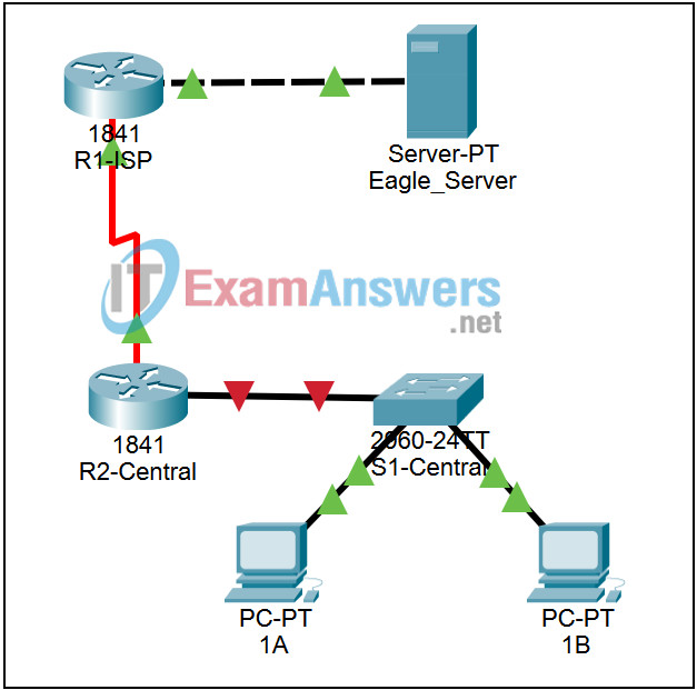
Topology Diagram:
Partial topology given; must be completed.

| Device | Interface | IP Address | Subnet Mask | Default Gateway |
|---|---|---|---|---|
| R1-ISP | Fa0/0 | 192.168.254.253 | 255.255.255.0 | N/A |
| S0/0/0 | 10.10.10.6 | 255.255.255.252 | ||
| R2-Central | Fa0/0 | 172.16.255.254 | 255.255.0.0 | N/A |
| S0/0/0 | 10.10.10.5 | 255.255.255.252 | ||
| S1-Central | VLAN 1 | 172.16.254.1 | 255.255.0.0 | 172.16.255.254 |
| PC-PT 1A | NIC | 172.16.1.1 | 255.255.0.0 | 172.16.255.254 |
| PC-PT 1B | NIC | 172.16.1.2 | 255.255.0.0 | 172.16.255.254 |
| Eagle Server | NIC | 192.168.254.254 | 255.255.255.0 | 192.168.254.253 |
Learning Objectives:
- Configure a router interface using a GUI
- Explore a routing table
- Configure a static route using a GUI
- Explore the routing of IP packets
Background:
Throughout the course, you will be using a standard lab setup created from actual PCs, servers, routers, and switches to learn networking concepts. At the end of each chapter, you will build increasingly larger parts of this topology in Packet Tracer, and analyze increasingly more complex protocol interactions. You have already studied a variety of application protocols, such as DNS, HTTP, TFTP, DHCP, and Telnet, and two transport layer protocols, TCP and UDP. You may have noticed that regardless of what application and transport protocols were involved, in Inbound and Outbound PDU Details view they were always encapsulated in IP Packets. In this activity, we will examine how the Internet Protocol, the dominant network layer protocol of the Internet, works in the context of a simple example of IP routing.
Task 1: Configure a router interface
There are problems on the local area network: PC-PT 1A cannot communicate with the Eagle Server (verify this in Realtime mode by pinging Eagle Servers IP address: 192.168.254.254). It appears there is a problem with the router. Mouse over the R2-Central router, and note the condition of the Fa0/0 interface (to which S1-Central is connected). This interface must have an IP address, subnet mask, and be turned on in order to act as the default gateway for the LAN. Click on router R2-Central, and go to the Config tab. At the end of the course, you will learn how to use the Cisco Internetwork Operating System (IOS) command line interface (CLI) to perform this task. For now, the Config tab is easier and will allow you to focus on the basic idea of IP routing. In the list shown, find INTERFACE, FastEthernet0/0. Add the IP address 172.16.255.254 with subnet mask of 255.255.0.0, and turn the port on. Close the router window. Verify that the router interface (port) is now working by using the mouse over. Try reaching Eagle Server. The request still fails. What are some possible reasons why?
Task 2: Examining routes
Use the Inspect tool (magnifying glass) to examine the routing table of R2-Central. You will see the router’s directly connected networks, but there is no way to reach the Eagle Server network.
Task 3: Configure a route using a GUI
Click on router R2-Central and go to the Config tab. In the list shown, find ROUTING, Static. Configure a default static route, using the address 0.0.0.0, mask 0.0.0.0, and the next hop of 10.10.10.6 (the S0/0/0 interface on the R1-ISP router) and click the Add button. This route is configured so that wherever packets from the 172.16.0.0 /16 LAN are destined, they will go to the R1-ISP router. Under GLOBAL, Settings, click on the Save button to save the interface and route configuration you have just done to NVRAM in case the router is power cycled. Use the Inspect Tool (magnifying glass) to examine the routing table of R2-Central again. You should now see the route you configured in the routing table.
Verify your work using feedback from the Check Results button and the Assessment Items tab. Test connectivity, in Realtime, by using ADD SIMPLE PDU to test connectivity between PC-PT 1A and the Eagle Server. The PDU, a one-shot ping, will appear in the User Created PDU List for future use as well. The first ping attempt will fail because the ARP tables are not populated; double click on Fire to send it again – this should be successful.
Task 4: Examine the routing of the IP packet
Switch to Simulation mode. Using the PDU you created in Task 3, trace the packet’s journey from PC-PT 1A to Eagle Server and back using the Capture / Forward button and examining the packet’s contents by either clicking on the envelope or clicking on the colored square in the Info column of the Event List.
Reflection:
What data can an IP Packet contain? What is meant by the phrase “the IP packet is routed”? What is a route? Where might things go wrong?
