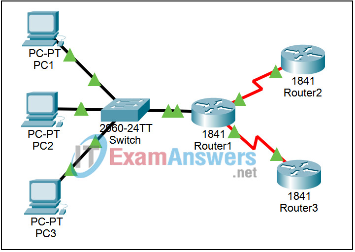
6.2.3 Packet Tracer – Show Unicast, Broadcast and Multicast Traffic Answers
Topology

Learning Objectives
- Verify connectivity
- Set up the simulation
- Run the simulation
Introduction:
Most traffic in a network is unicast. If a PC sends an ICMP echo request to a remote router, the source address in the IP packet header is the IP address of the PC, and the destination address in the IP packet header is the IP address of the interface on the router. The packet is sent only to the intended destination.
Using the ping command or the Add Complex PDU feature of Packet Tracer, you can directly ping broadcast addresses. RIP, Routing Information Protocol, is used by routers to periodically exchange routing information between routers. Version 1 of RIP broadcasts periodic updates out of every interface that is configured for RIP. Although these broadcasts are only intended for other routers, all devices must process this information. Version 2 of RIP multicasts periodic updates out of every interface that is configured for RIP. These packets are sent to multicast address 224.0.0.9, which represents the group of RIP version 2 routers. Although these packets are received by other devices, they are dropped at Layer 3 by all devices except RIP version 2 routers, with no other processing required. This activity will examine unicast, broadcast, and multicast behavior.
Task 1: Verify connectivity
Step 1. Access PC1
Click on PC1. Go to the Command Prompt on the Desktop.
Step 2. Ping Router3
Enter the command ping 10.0.3.2. The ping should succeed. Minimize the Command Prompt window.
Task 2: Setup the simulation
Step 1. Enter Simulation mode
Click the Simulation tab to enter Simulation mode. Restore the PC1 window. Enter the command ping 10.0.3.2. Minimize the Command Prompt window.
Step 2. Set Event List Filters
We want to capture only ICMP and RIP events. In the Event List Filters section, click the Edit Filters button. Select only ICMP and RIP events.
Task 3: Run the simulation
Step 1. Examine unicast traffic
The PDU at PC1 is an ICMP echo request intended for the serial interface on Router3. Click the Capture / Forward button repeatedly and watch while the echo request is sent to Router3 and the echo reply is sent back to PC1. Stop when the first echo reply reaches PC1.
In the Simulation Panel Event List section, the last column contains a colored box that provides access to detailed information about an event. Click the colored box in the last column for the first event. The PDU Information window opens.
Examine the Layer 3 information for all of the events. Notice that both the source and destination IP addresses are unicast addresses that refer to PC1 and the serial interface on Router3. Click the Reset Simulation button.
Step 2. Examine broadcast traffic
Click on the Add Complex PDU button (the open envelope in the far right). Click on PC 1 to serve as the source for this test message. For the destination address enter the broadcast address 255.255.255.255. For the sequence number enter 1; for the time enter 0. Click on the Create PDU button; this test broadcast packet now appears in the Event List (as a “measured event”) and in the User Created PDU List (as a created packet that you can edit). Click the Capture / Forward button twice. This packet will be sent to the switch, and forwarded to PC 2, PC 3, and the router. Examine the Layer 3 information for all of the events. Notice that the destination IP address 255.255.255.255, is the IP broadcast address. After you are done examining the broadcast behavior, delete the test packet. (You can delete all of Scenario 0, and reset the simulation, by using the Delete button to the right of the New button.)
Step 3. Examine multicast traffic
Click the Capture / Forward button again. Three RIP version 2 packets are at Router1 waiting to be multicast out each interface.
Examine the contents of these packets by opening the PDU Information Window and click the Capture / Forward button again. The packets are sent to the two other routers and the switch. The routers accept and process the packets, because they are part of the multicast group. Click the Capture / Forward button again. The packets are sent to the three hosts. The hosts reject and drop the packets.
Examine the Layer 3, Layer 4, and Layer 7 information for all of the RIPv2 events. Notice that the destination IP address 224.0.0.9, is the IP multicast address for RIPv2 routers. Notice that the updates reaching the PCs are dropped at Layer 3 and no additional processing is done.
