5.2.2 Packet Tracer – Routers Segment Broadcast Domains Answers
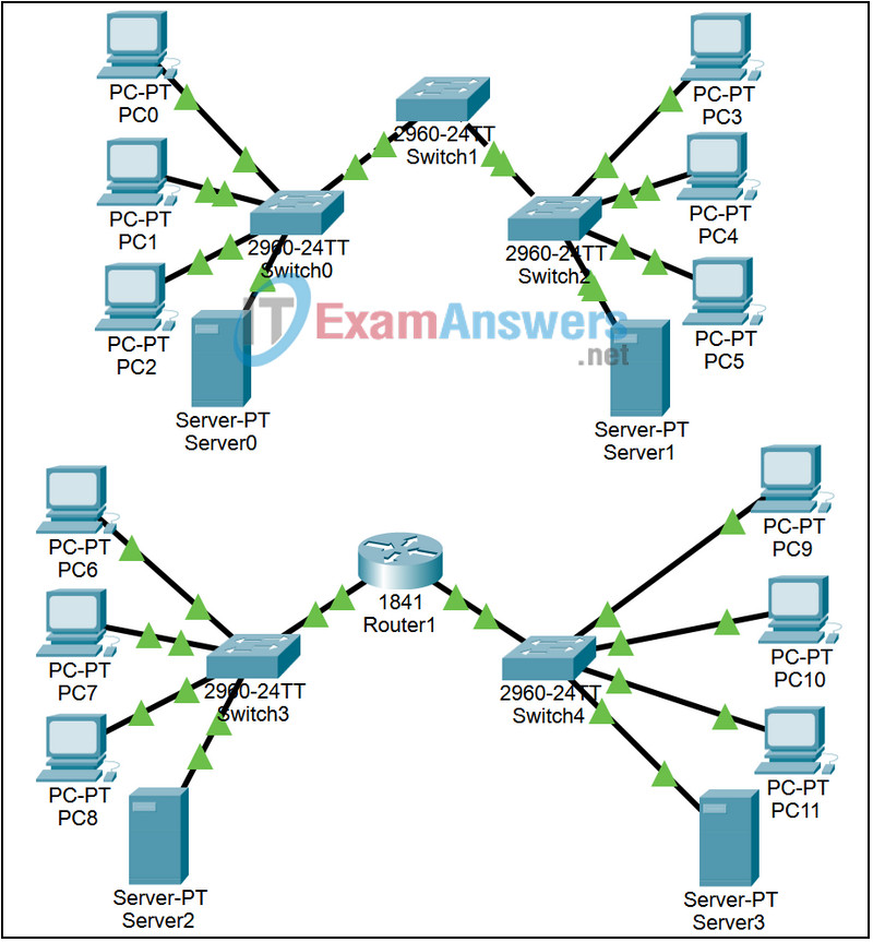
Topology

Learning Objectives
- Examine the behavior of pinging the broadcast address on an un-segmented, switched network
- Examine the behavior of pinging the broadcast address on a segmented, routed network
Introduction:
Broadcast packets are sent to every host in a network. Broadcasts generate excessive traffic on the network and require every device on the network to examine the packet. The region of a network that receives a broadcast is called a broadcast domain. Layer 2 switches extend broadcast domains. Devices that perform Layer 3 routing processes divide broadcast domains.
Sometimes it may be more convenient to model separate networks in the same Packet Tracer file. In this file there are two different networks. Packet Scenario 0 is switched and packet Scenario 1 is routed.
NOTE: When switched networks are first loaded in Packet Tracer, you may experience a delay in the link lights turning green while they run their initial Spanning Tree Protocol Calculations. Toggling from Realtime to Simulation Mode 3 or 4 times will accelerate this process.
Task 1: Run the Simulation Using Scenario 0
Step 1. Enter simulation mode
Click between the Simulation and Realtime modes three or four times to clear the Spanning Tree Protocol on the switch ports; leave Packet Tracer in Simulation mode.
Step 2. Step through Scenario 0
The file will have loaded with Scenario 0, consisting of a Simple PDU (one shot ping) from PC 0 to the broadcast address of 255.255.255.255. Click on the colored Info square next to this packet’s listing in the Event List (or equivalently, click on the packet envelope displayed at PC 0) and examine the OSI Model and Outbound PDU Details views of the packet. Then click the Capture / Forward button and watch the broadcast travel to all devices in the switched network. Examine the packet at different points in its journey. If you receive a “Buffer Full” message, click the View Previous Events button. The extent of these broadcasts defines a broadcast domain. You may want to run the animation again using the Reset Simulation button and the Auto Capture / Play button or create your own scenarios where you add test packets to the network.
Task 2: Run the simulation Using Scenario 1
Step 1. Switch to Scenario 1
Near the lower right of the GUI, the scenario is currently set at Scenario 0. Use the pull down menu to go to Scenario 1, where a broadcast packet is being sent from PC 6 to the broadcast address of 255.255.255.255.
Step 2. Step through the Scenario 1
Click on the colored Info square next to this packet’s listing in the Event List (or equivalently, click on the packet envelope displayed at PC 6) and examine the OSI Model and Outbound PDU Details views of the packet. Then click the Capture / Forward button and watch the broadcast travel to all devices up to and including the router interface. Examine the packet at different points in its journey. If you receive a “Buffer Full” message, click the View Previous Events button. The extent of these broadcasts defines a broadcast domain, which in this case ends at the router. You may want to run the animation again using the Reset Simulation button and the Auto Capture / Play button or create your own scenarios where you add test packets to the network.
