
Packet Tracer - Subnet Scenario 2
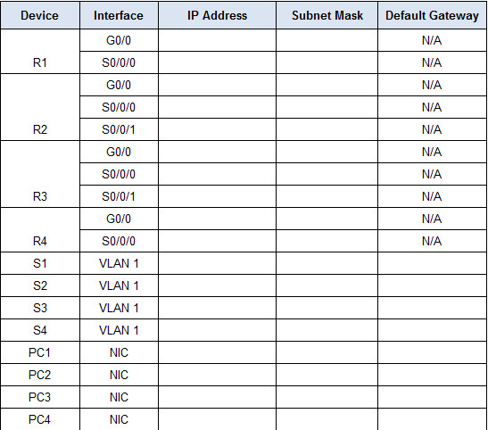
Addressing Table
Objectives
Part 1: Design an IP Addressing Scheme
Part 2: Assign IP Addresses to Network Devices and Verify Connectivity
Scenario
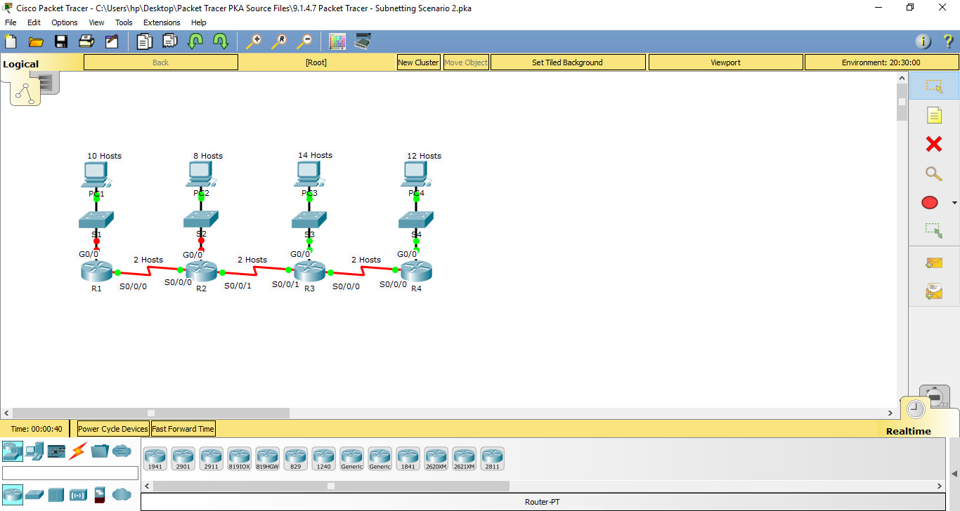
In this activity, you are given the network address of 172.31.1.0 /24 to subnet and provide the IP addressing for the network shown in the Topology. The required host addresses for each WAN and LAN link are labeled in the topology.
Part 1: Design an IP Addressing Scheme
Step 1: Subnet the 172.31.1.0/24 network based on the maximum number of hosts required by the largest subnet.
a. Based on the topology, how many subnets are needed? 7
b. How many bits must be borrowed to support the number of subnets in the topology table? 3
c. How many subnets does this create? 16
d. How many usable host addresses does this create per subnet? 8
Note: If your answer is less than the 14 maximum hosts required for the R3 LAN, then you borrowed too many bits.
e. Calculate the binary value for the first five subnets. Subnet zero is already shown.
Net 0: 172 . 31 . 1 . 0 0 0 0 0 0 0 0
Net 1: 172 . 31 . 1 . 0 0 1 0 0 0 0 0
Net 2: 172 . 31 . 1 . 0 1 0 0 0 0 0 0
Net 3: 172 . 31 . 1 . 0 1 1 0 0 0 0 0
Net 4: 172 . 31 . 1 . 1 0 0 0 0 0 0 0
f. Calculate the binary and decimal value of the new subnet mask.
11111111.11111111.11111111. 1 1 1 0 0 0 0 0
255 . 255 . 255 . 224
g. Complete the Subnet Table, listing all available subnets, the first and last usable host address, and the broadcast address. The first subnet is done for you. Repeat until all addresses are listed.
Note: You may not need to use all rows.
Subnet Table
| SUBNET # | SUBNET ADDRESS | SUBNET MASK | FIRST USABLE | LAST USABLE | BROADCAST |
|---|---|---|---|---|---|
| 0 | 172.31.1.0 | 255.255.255.224 | 172.31.1.1 | 172.31.1.30 | 172.31.1.31 |
| 1 | 172.31.1.32 | 255.255.255.224 | 172.31.1.33 | 172.31.1.62 | 172.31.1.63 |
| 2 | 172.31.1.64 | 255.255.255.224 | 172.31.1.65 | 172.31.1.94 | 172.31.1.95 |
| 3 | 172.31.1.96 | 255.255.255.224 | 172.31.1.97 | 172.31.1.126 | 172.31.1.127 |
| 4 | 172.31.1.128 | 255.255.255.224 | 172.31.1.129 | 172.31.1.158 | 172.31.1.159 |
| 5 | 172.31.1.160 | 255.255.255.224 | 172.31.1.161 | 172.31.1.190 | 172.31.1.191 |
| 6 | 172.31.1.192 | 255.255.255.224 | 172.31.1.193 | 172.31.1.222 | 172.31.1.223 |
| 7 | 172.31.1.224 | 255.255.255.224 | 172.31.1.225 | 172.31.1.254 | 172.31.1.255 |
Step 2: Assign the subnets to the network shown in the topology.
When assigning the subnets, keep in mind that routing is necessary to allow information to be sent throughout the network.
a. Assign Subnet 0 to the R1 LAN: 172.31.1.0 /27
b. Assign Subnet 1 to the R2 LAN: 172.31.1.32 /27
c. Assign Subnet 2 to the R3 LAN: 172.31.1.64 /27
d. Assign Subnet 3 to the R4 LAN: 172.31.1.96 /27
e. Assign Subnet 4 to the link between 172.31.1.128 /27
f. Assign Subnet 5 to the link between 172.31.1.160 /27
g. Assign Subnet 6 to the link between 172.31.1.192 /27
Step 3: Document the addressing scheme.
Complete the Addressing Table using the following guidelines:
a. Assign the first usable IP addresses to routers for each of the LAN links.
b. Use the following method to assign WAN link IP addresses:
· For the WAN link between R1 and R2, assign the first usable IP address to R1 and last usable IP address R2.
· For the WAN link between R2 and R3, assign the first usable IP address to R2 and last usable IP address R3.
· For the WAN link between R3 and R4, assign the first usable IP address to R3 and last usable IP address R4.
c. Assign the second usable IP addresses to the switches.
d. Assign the last usable IP addresses to the hosts.
Part 2: Assign IP Addresses to Network Devices and Verify Connectivity
Most of the IP addressing is already configured on this network. Implement the following steps to complete the addressing configuration.
Step 1: Configure IP addressing on R1 and R2 LAN interfaces.
Step 2: Configure IP addressing on S3, including the default gateway.
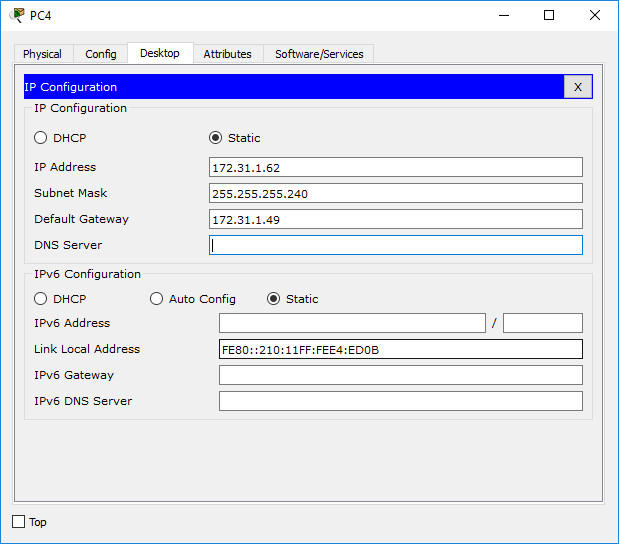
Step 3: Configure IP addressing on PC4, including the default gateway.
Step 4: Verify connectivity.
You can only verify connectivity from R1, R2, S3, and PC4. However, you should be able to ping every IP address listed in the Addressing Table.
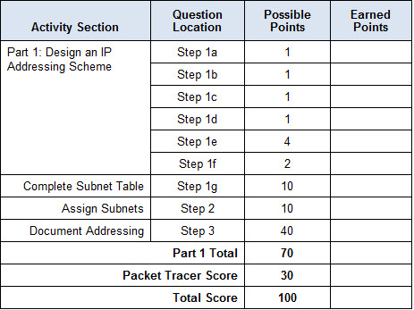
Suggested Scoring Rubric
Instructions
Addressing Table
Addressing Table
| Device | Interface | IP Address | Subnet Mask | Default Gateway |
|---|---|---|---|---|
| R1 | G0/0 | 172.31.1.1 | 255.255.255.224 | N/A |
| S0/0/0 | 172.31.1.129 | 255.255.255.224 | N/A | |
| R2 | G0/0 | 172.31.1.33 | 255.255.255.224 | N/A |
| S0/0/0 | 172.31.1.158 | 255.255.255.224 | N/A | |
| S0/0/1 | 172.31.1.161 | 255.255.255.224 | N/A | |
| R3 | G0/0 | 172.31.1.65 | 255.255.255.224 | N/A |
| S0/0/0 | 172.31.1.190 | 255.255.255.224 | N/A | |
| S0/0/1 | 172.31.1.193 | 255.255.255.224 | N/A | |
| R4 | G0/0 | 172.31.1.97 | 255.255.255.224 | N/A |
| S0/0/0 | 172.31.1.222 | 255.255.255.224 | N/A | |
| S1 | VLAN 1 | 172.31.1.2 | 255.255.255.224 | 172.31.1.1 |
| S2 | VLAN 1 | 172.31.1.34 | 255.255.255.224 | 172.31.1.33 |
| S3 | VLAN 1 | 172.31.1.66 | 255.255.255.224 | 172.31.1.65 |
| S4 | VLAN 1 | 172.31.1.98 | 255.255.255.224 | 172.31.1.97 |
| PC1 | NIC | 172.31.1.30 | 255.255.255.224 | 172.31.1.1 |
| PC2 | NIC | 172.31.1.62 | 255.255.255.224 | 172.31.1.33 |
| PC3 | NIC | 172.31.1.94 | 255.255.255.224 | 172.31.1.65 |
| PC4 | NIC | 172.31.1.126 | 255.255.255.224 | 172.31.1.97 |
R1>enable
R1#conf t
R1(config)#int g0/0
R1(config-if)#ip add 172.31.1.1 255.255.255.240
R1(config-if)#no shR1(config-if)#int s0/0/0
R1(config-if)#ip add 172.31.1.65 255.255.255.240
R1(config-if)#no sh
R2>en
R2#conf t
R2(config-if)#int s0/0/0
R2(config-if)#ip add 172.31.1.78 255.255.255.240
R2(config-if)#no shR2(config-if)#int s0/0/1
R2(config-if)#ip add 172.31.1.81 255.255.255.240
R2(config-if)#no sh
S3>en
S3#conf t
S3(config)#int vl1
S3(config-if)#ip add 172.31.1.34 255.255.255.240
S3(config-if)#no sh
S3(config-if)#ip de 172.31.1.33
Download Pka file and PDF file below:

9.1.4.7 Packet Tracer - Subnetting Scenario 2.pka Completed 100% 534.06 KB 4891 downloads
...
