We know that a switch has many advantages over a hub. One of the major reason behind switch’s popularity over hub is its Unicast transmission method. A Switch has ability to transmit a frame only to a device that deserve to receive it. For this, switch uses its MAC Address Table to make a forwarding decision. Whenever a switch is powered on, its MAC address table is blank. When the switch receives a frame on an interface, it places the source MAC address of sending device in its MAC address table. However, the switch has still no idea about the destination MAC address hence, it floods the frame to all its active interfaces except the interface from where it receives that frame. This is what called flooding.
The device, of which the MAC address matches, answers and sends a frame back, then the switch takes the source MAC address from the received frame and place it in the MAC address table. Once the switch has learned all the MAC addresses and the MAC address table is fully updated, the devices can make a one-to-one communication (unicast). From now, the frames will only be forwarded the between the devices that deserve to participate in the communication process. That is why the layer-2 switches are considered better than hubs. We know that -in a hub-based network, all the each frame is forwarded out to all the active ports every time.
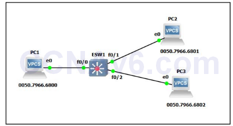
We will use the following topology to explain how does a switch build the MAC address table?

In the preceding figure, there are four hosts attached to a switch. When the switch is powered on, its MAC address table will be blank.
- We assume that PC1 sends a frame to PC3.
- The switch will receive the frame on the F0/ 0 interface and will place the source MAC address in the MAC address table.
- Since the MAC address of PC3 will not be available in the switch’s MAC address table, the frame will be forwarded out (flooded) to all the active interfaces.
- PC3 will receive the frame and will respond to PC1. The switch will receive this frame on the interface F0/ 2 and will place the source MAC address in the MAC address table.
- Now, PC1 and PC3 can make a one-to-one communication to each other. However, PC2 will not be able to see the frames transmitting between PC1 and PC3. When a device will communicate to PC2, its MAC address will also be updated in the switch’s MAC address table.
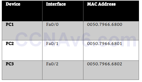
- Now, switch will have all the MAC addresses in its MAC address table and all the devices will be able make one-to-one communication. Once the MAC address table is fully updated, it will look like the following.

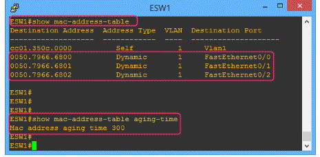
However, if the devices do not transfer frames to the switch again within a certain amount of time called aging-time, the switch will remove the MAC addresses of those devices from the MAC address table to keep the MAC address table up-to-dated.
The following figure shows the MAC address table and the default aging-time.

In the preceding figure Dynamic means the entries are added dynamically. However, MAC addresses can be defined manually this will be called Static address type.
That’s all about how a switch does build the MAC address table? Hope, it has helped you and you enjoyed it.
