1. Describe routing concepts
Routers are primarily responsible for logical addressing and best path selection. They forward packets between different subnets, VLANs and across the WAN.
They build a routing table with routes comprised of network prefix, metric and next hop address. The router selects the route based on longest match rule and forwards packets to the next hop router (neighbor). There is support for load balancing, flow control and error recovery as well.
Each packet has a source and destination IP address. The router does a routing table lookup for a route to the destination subnet. The packet is then forwarded to the next hop address associated with the selected route.
Packet handling along the path through a network
ARP is a layer 3 network protocol that resolves a known IP address to an unknown MAC address. The local host must know the MAC address of the remote host before packets can be sent. That enables packet forwarding between local and remote host (server). The host checks the local ARP cache for an entry with the IP address and MAC address of a server. The host sends an ARP request to the default gateway if there is no local ARP entry. The default gateway (router) sends a proxy ARP broadcast and returns the MAC address for a server to the host In addition all routers between source and destination update their ARP table bindings (mappings). The switches note the server MAC address as well and update their MAC address table.
The output from show arp command lists the entries in the ARP cache table. The router adds the IP address and associated hardware (MAC) address for each ARP request to the cache.
The Aging field with (-) indicates the MAC address of the interface (Gi0/0) on Router-1. It does not age out from the table. The default ARP entry aging timer is 240 minutes. At that point the entry is flushed and new ARP request is required. The interface field signifies where the MAC address was learned. The serial interfaces do not have a MAC address.
router# show arp
Protocol  Address     Aging  Hardware Address Type Interface
Internet  172.16.1.3  -      0000.000c.cccc ARPA   Gi0/0
Internet  172.16.1.2  12     0000.000b.bbbb ARPA   Gi0/0
Internet  172.16.1.1  12     0000.000a.aaaa ARPA   Gi0/0
Internet  172.16.2.2  12     0000.000d.dddd ARPA -
Internet  172.16.3.1  12     0000.1234.5678 ARPA -
The source and destination MAC address are updated by routers as frames are forwarded between routers. The source MAC address is the router egress interface and destination MAC address is the neighbor ingress interface.
The forwarding decisions for routers are based on destination IP address and not destination MAC address. The source and destination IP address do not change between source and destination hosts.
Any layer 3 device such as a host or a router will write an IP header to create a packet with the source IP address and destination IP address.
The IP header has a field called Time-to-Live (TTL) that has a default value of 255. The purpose of TTL is to prevent packets from infinitely looping as a result of a routing loop. The TTL field is decremented by one with each router hop. That guarantees the packet will be discarded after 255 hops.
ARP for Default Gateway
Refer to the network drawing. Host-1 is establishing an initial connection to Server-1. The host sends an ARP broadcast for the MAC address of the default gateway if it isn’t in the host ARP cache. It is the default gateway (router) that eventually does a proxy ARP request for the server MAC address.
Host-1 sends a layer 2 ARP broadcast frame on the local VLAN to request the MAC address of the default gateway. That is required before sending an ARP request to the default gateway router for the MAC address of Server-1.
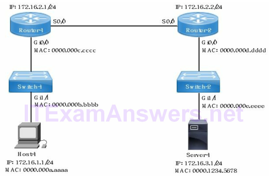
The following describes the network addressing of the broadcast packet sent from Host-1 to start an initial session with Server-1.
- source MAC address = 0000.000a.aaaa
- destination MAC address = ffff.ffff.ffff
- source IP address = 172.16.1.1/24
- destination IP address = 172.16.3.1/24
Forwarding decision based on route lookup
The router builds a routing table with multiple routes (prefixes). The routes are assigned an administrative distance and metric cost.
Route Selection:
The administrative distance is a value assigned to a routing protocol. Metric is a path cost assigned to a specific route. The administrative distance and metric assigned to a route will determine what route is installed in the routing table.
The router installs the route with the lowest administrative distance including connected, static and default routes. In this example EIGRP has the lowest administrative distance and would be installed in the routing table.
- OSPF: 172.16.1.0/24
- RIPv2: 172.16.1.0/24
- EIGRP (Internal): 172.16.1.0/24
The route with the lowest metric is installed when there are multiple routes from the same routing protocol to the same destination. Equal cost load balancing is enabled when the route metrics to the same destination are equal. Administrative distance is configurable as well to influence route selection.
The following is an example of multiple routes from different routing protocols with different subnet mask (prefix) lengths. As a result they are all considered to be different destinations and all are installed in the routing table.
- OSPF: 172.16.1.0/21
- RIPv2: 172.16.1.0/23
- EIGRP: 172.16.1.0/27
Packet Forwarding:
The longest match rule is used to select a route already installed in the routing table as a forwarding decision. Each route has a specific prefix (subnet mask) length. The route with the longest prefix is selected from multiple routes within the same subnet range. For instance 172.16.0.0/22 has a longer prefix than 172.16.0.0/18 and used to forward packets to that destination.
Example 1:
The following is a list of routes and options for packet handling of an incoming packet. The router would select route 192.168.1.0/28 based on the longest match rule for packet forwarding to destination subnet 192.168.1.10/30
A. 192.168.1.0/24
B. 192.168.1.0/26
C. 192.168.1.0/28
D. gateway of last resort
E. packet discarded
Example 2:
Router-1 must select a route to forward packets to 172.16.4.0/28 network. Select the routing method, next hop address and router interface based on the routing table exhibit?
router-1# show ip route
Codes: C - connected, S - static, R - RIP, M - mobile, B - BGP
       D - EIGRP, EX - EIGRP external, O - OSPF, IA - OSPF inter area
       N1 - OSPF NSSA external type 1, N2 - OSPF NSSA external type 2
       E1 - OSPF external type 1, E2 - OSPF external type 2
       o - ODR, P - periodic downloaded static route
Gateway of last resort is not set
172.16.0.0/24 is variably subnetted, 4 subnets, 2 masks
C 172.16.1.0/24 is directly connected, GigabitEthernet0/0
C 172.16.200.0/30 is directly connected, Serial0/0
C 172.16.200.16/30 is directly connected, Serial0/1
D 172.16.200.32/30 [90/1234567] via 172.16.200.2, Serial0/0
[90/1234567] via 172.16.200.18, Serial0/1
D 172.16.2.0/27 [90/1234567] via 172.16.200.18, Serial0/1
D 172.16.4.0/27 [90/1463212] via 172.16.200.2, Serial0/0
R 172.16.4.0/26 [120/3] via 172.16.200.17, Serial0/2
A. EIGRP, 172.16.200.32/30, Serial0/0
B. Connected, 172.16.200.16/30, Serial0/1
C. Connected, 172.16.1.0/24, GigabitEthernet0/0
D. EIGRP, 172.16.4.0/27, Serial0/0
E. RIPv2, 172.16.4.0/26, Serial0/2
The router selects the route with the longest prefix (subnet mask length) where there are multiple routes to the same destination. It is referred to as the longest match rule. The following EIGRP route has the longest prefix (/27) to the destination 172.16.4.0 subnet. The next hop address to forward packets destined for 172.16.4.0 is 172.16.200.2 via S0/0 local interface.
D 172.16.4.0/27 [90/1463212] via 172.16.200.2, Serial0/0
The routes 172.16.4.0/26 (RIPv2) and 172.16.4.0/27 (EIGRP) have different prefix lengths so they are considered different destinations by router. The router will install multiple routes from different routing protocols as a result. The administrative distance only applies to routes with the same subnet and prefix length (same destination).
EIGRP Metrics
The route with lowest metric is selected when multiple routes exist to the same destination (172.16.3.0) with same prefix length (/24) from the same routing protocol. The bandwidth and delay are EIGRP defaults used to calculate metric value for a link. The delay is a fixed value based on interface speed. The link bandwidth is not cumulative with EIGRP.
Refer to the network topology drawing. There are multiple paths from 172.16.3.0 (source) to 172.16.2.0 (destination). Each path between source and destination is comprised of multiple individual links. EIGRP examines the links and determines the lowest bandwidth link for each path. The path with highest bandwidth (lowest metric) from among all lowest bandwidth links is selected (bolded path).
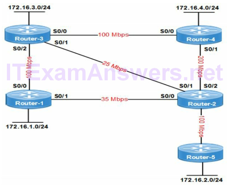
Router-3 -> Router-4 -> Router-2 -> Router-5 = 100 Mbps
Router-3 -> Router-1 -> Router-2 -> Router-5 = 35 Mbps
Router-3 -> Router-2 -> Router-5 = 25 Mbps
EIGRP Variance Command
EIGRP does support load balancing across unequal links to the same destination with the variance feature. The default for EIGRP is equal-cost (metric) load balancing.
The variance command allows for unequal cost load balancing between EIGRP enabled interfaces. The default is to forward traffic across the link with the lowest metric when there are multiple links to the same destination. The route has already been selected based on longest match rule.
EIGRP install all paths that have a metric less than the variance * the best metric in the routing table. The route must meet the feasibility condition to prevent routing loops. The feasibility condition states that, the Advertised Distance (AD) of a route must be lower than the feasible distance of the current successor route. Configuring variance by a factor of two instructs the router to include all routes less than 2 times the lowest metric. Note as well that the variance factor of two is the minimum.
RIPv2 Metrics
RIPv2 routes are selected based on the hop count only. The hop count is the number of routers between source and destination. The route with the lowest hop count to the destination is selected.
The maximum hop count (metric) for distance vector routing protocol RIPv2 is 15. That is the same maximum hop count as RIPv1. The packet is discarded at router hop 15. RIPv2 does support load balancing across a maximum 4 paths between source and destination. The paths must have lowest and equal hop count to load balance packets.
OSPF Metrics
OSPF selects a path based on link cost (bandwidth) between source and destination. The cost of each link is calculated and added to arrive at a cumulative metric cost for the path. The minimum cost that can be assigned to any link is 1. The default OSPF reference bandwidth is 100 Mbps. The following formula is used to calculate OSPF link cost.
cost = 100 Mbps / link bandwidth
Frame Rewrite
The source IP address and destination IP address does not change between network endpoints. The source MAC address and destination MAC address is rewritten at each layer 3 hop (router).
The local router updates (rewrite) source MAC address and destination MAC address in the frame header before forwarding the packet. The source MAC address is the local outbound router Ethernet interface. The destination MAC address is the MAC address of the next hop (neighbor) router Ethernet interface.
Serial interfaces do not have MAC addresses. As a result frame rewrite is assigned differently on serial point-to-point links. The router assigns the Ethernet interface where the frame was learned as source MAC address. In addition the router assigns the device MAC address assigned to the neighbor router as destination MAC address.
Frame Rewrite Examples
Example 1:
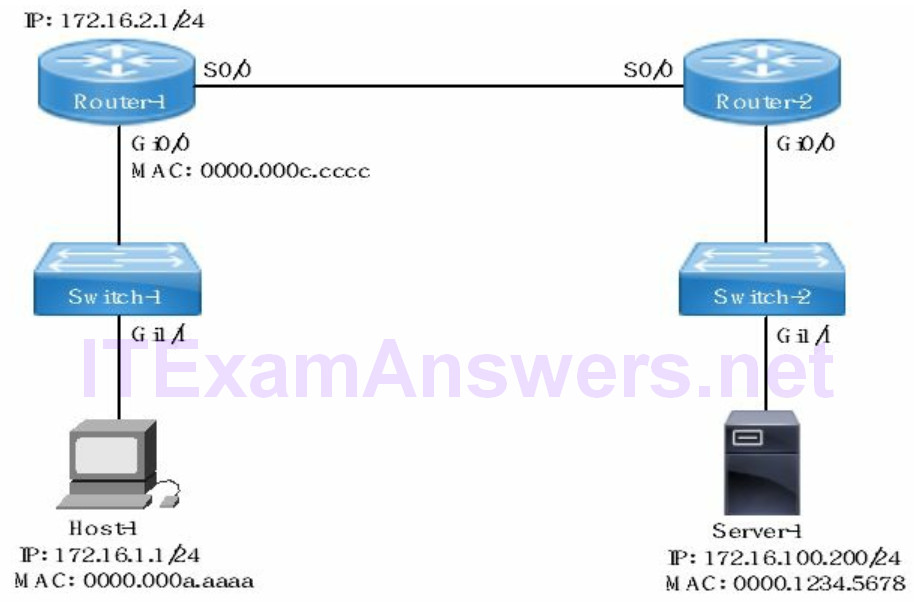
Refer to the network drawing. Host-1 has established a session with Server-1 and sending a new file. Host-1 sends all packets with the MAC address assigned to its network interface card as the source MAC address. The destination MAC address for the packet is the default gateway (router-1) Ethernet interface Gi0/0. That was obtained from the ARP request sent before the session started with Server-1. Switches forward frames and are never a destination.
- source MAC address as the packet leaves Host-1 = 0000.000a.aaaa
- destination MAC address as the packet leaves Host-1 = 0000.000c.cccc
Example 2:
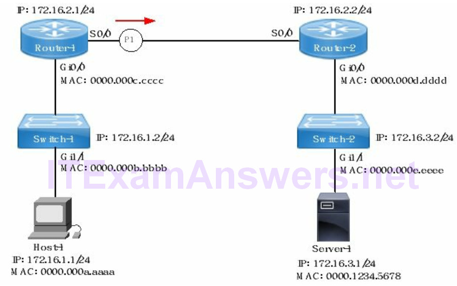
Refer to the network topology drawing. The router is the only network device that rewrites source and destination MAC address. The source MAC address is derived from the local router (Router-1) egress Ethernet interface.
The destination MAC address is derived from the next hop router (Router-2) ingress Ethernet interface. WAN serial interfaces do not have an assigned MAC address. As a result, Router-1 assigns the MAC address of the Ethernet interface (Gi0/0) where the packet was learned as source MAC address.
Router-1 assigns the MAC address of Router-2 Ethernet interface Gi0/0 as the destination MAC address. The MAC address of Router-2 is obtained from the router ARP table.
The source and destination MAC address of the packet at P1 when it is forwarded to Router-2 is as follows:
- source MAC address = 0000.000c.cccc
- destination MAC address = 0000.000d.dddd
2. Interpret the components of a routing table
Each routing table is comprised of multiple routes (entries). The router does a routing table lookup for the best route to the destination subnet. It is used for packet forwarding to the destination subnet.
1. Routing protocol code is the route source.
2. Destination subnet is the address of the remote network.
3. Administrative distance is the trustworthiness of the route source.
4. Metric is the path cost to the destination subnet.
5. Next hop is the interface of a neighbor router specified with a route.
6. Local interface is the exit interface used to forward packet to next hop address.
Example:
O 192.168.12.236 /30 [110/128] via 192.168.12.233, 00:35:36, Serial0/0
- Routing protocol code = O (OSPF)
- Destination subnet (prefix) = 192.168.12.236 /30
- Administrative distance = 110
- Metric = 128
- Next hop address = 192.168.12.233
- Local egress interface = Serial0/0
Routing Protocol Codes
The output of show ip route command lists the available routes. The protocol code assigned to the route signifies the source where the route was learned.
Table 1: Routing Protocol Codes
| EGP | E |
| EIGRP | D |
| Host (/32) | L |
| OSPF | O |
| Default Route | S* |
| Static Route | S |
3. Describe routing table selection based on multiple routing sources
The route with the lowest administrative distance will be installed in the routing table. For instance EIGRP (90) has a lower administrative distance than OSPF (110) and RIPv2 (120). The result is the EIGRP route is installed in the routing table. The static route with administrative distance of 255 is not installed in the routing table.
Table 2: Administrative Distances for Routing Protocols
| Directly Connected | 0 |
| Static Route | 1 |
| eBGP | 20 |
| EIGRP (Internal) | 90 |
| OSPF | 110 |
| RIPv2 | 120 |
| External EIGRP | 170 |
4. Configure, verify and troubleshoot InterVlan Routing
Router-on-a-Stick
Refer to the network drawing. Host-1 and Server-1 are on different subnets. As a result routing is required to forward packets between the subnets. Layer 2 switches do not provide routing services or proxy ARP.
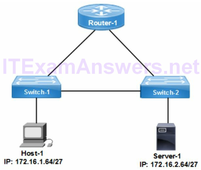
In addition Switch-1 has no default gateway configured and would discard all packets destined for a remote subnet. Assigning Host-1 and Server-1 to the same or different VLANs would not enable communication between them since they are not directly connected. The easiest solution to enable communication between different VLANs on each switch is router-on-a-stick. The alternative is a layer 3 switch configured with SVIs.
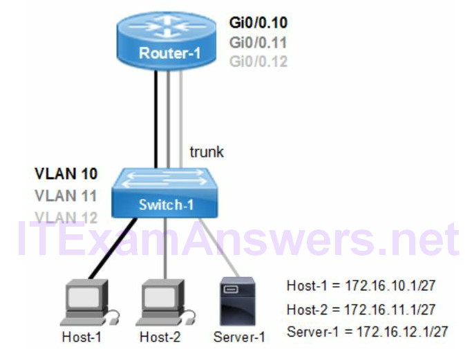
Configure
The following steps are required to configure router-on-a-stick
1. Configure trunk mode on switch uplink to router and allow VLANs.
2. Configure sub-interfaces on router with dot1q encapsulation for each VLAN
3. Configure each subinterface with an IP address in the same subnet as host VLAN.
Verify
The following show commands are all options to verify the subnet assigned to each VLAN on the router subinterface.
- show ip route
- show running-config
- show protocols
Troubleshooting InterVLAN Routing
The following are some common causes of InterVLAN errors.
- incorrect VLAN encapsulation on subinterface
- incorrect subnet mask assigned to subinterface
- trunk mode not enabled on switch uplink port
Switch Virtual Interface (SVI)
Switch-2 is a layer 2 device and has no routing (layer 3 forwarding) enabled. The switch makes forwarding decisions based on the destination MAC address.
Network management access (Telnet/SSH) to a switch requires a default gateway on the switch. The purpose of a default gateway is to forward packets destined for remote subnets to an upstream router. In addition the switch must be configured with an SVI for Layer 3 connectivity
- The switch is configured with ip default-gateway command
- The switch is configured with a Layer 3 VLAN interface called an SVI
- The VLAN interface is assigned an IP address for layer 3 connectivity
- The Telnet session from a host or router connects to the SVI address
The switch forwards any packets that are not on the local subnet to the default gateway (router). The host for instance is on a remote subnet from where Telnet is initiated. The SVI management VLAN must be assigned to the same subnet as the default gateway (router) interface.
switch(config)# ip default-gateway 192.168.1.254
switch(config)# interface vlan 100
switch(config-if)# ip address 192.168.1.2 255.255.255.0
switch(config-if)# no shutdown
5. Compare and contrast static routing and dynamic routing
The static route is a manually configured route added to the routing table. It has an administrative distance of 1 making it a preferred route over all dynamically learned routes. The static route is configured from global configuration mode. The next hop to a destination subnet is configured as an IP address or local exit interface.
- The two advantages of static routes are security and minimal router CPU processing. The static routes are manually configured, enabled and managed by the network administrator. Route selection and forwarding packets to the destination subnet is deterministic.
- Dynamic routing protocols have security vulnerabilities that make them less desirable when connecting firewalls for instance. In addition dynamic routing protocols require more CPU utilization for hello packets, route calculation, convergence and routing updates.
6. Compare distance vector and link-state routing protocols
- Routing protocols are either link-state or distance vector. The distance vector protocol assigns metric based on hop count. The best path selected has least number of hops.
- Link-state routing protocols discover the routing topology for enabled links and calculate the shortest (best) path. In addition they only send event-triggered routing updates. For instance a link failure on a router would trigger a routing reconvergence. They advertise classless routes as a default and automatic summarization is disabled. Classless routing protocols advertise the subnet in routing updates
- The router running a distance vector routing protocol will send routing table updates at regular intervals to neighbors. In addition the routing table is updated based on route advertisements from neighbors. The distance vector routing protocol is RIPv2.
- The purpose of split horizon is to prevent routing loops. It is enabled as a feature of distance vector routing protocols. It prevents routes from being advertised on the same interface where they were learned.
- The purpose of route poisoning is to prevent routing loops. It is a feature of distance vector routing protocols. The hop count for a route is increased so it is larger than the maximum supported. The router advertises the route to a neighbor as unreachable.
The following summarizes the differences between distance vector and link-state routing protocols.
Distance Vector Routing Protocols
- RIPv2, EIGRP
- Metric = distance based on hop count
- Regular routing table updates to neighbors
- Slower network convergence
- Small network
- Not scalable
Link-State Routing Protocols
- OSPF, IS-IS
- Metric = path cost
- Event-triggered routing updates
- Global topology database
- Scalable
7. Compare and contrast interior and exterior routing protocols
Interior gateway routing protocols (IGP) advertise routes between routing domains that are privately managed. The IGP routing protocols include RIPv2, OSPF and EIGRP. BGP is an exterior routing protocol that enables routing across external routing domains managed by service providers (ISP).
8. Configure, verify and troubleshoot IPv4 and IPv6 static routing
Default Route
The default route is referred to as gateway of last resort packet forwarding. Any route, where no match exists, is forwarded to the default route next hop address. In the context of a router, the default route is often configured to forward packets to the internet. The administrative distance of a default route is 1 (the same as a static route).
The default route enables connectivity to the internet with a single route in the routing table. That minimizes the routing table size and router CPU utilization. Route processing and forwarding is offloaded to the internet service provider.
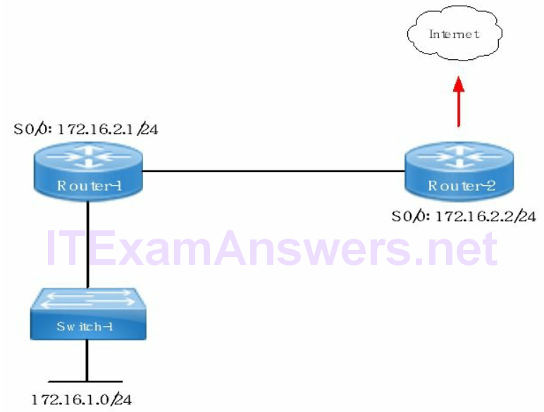
Packets arriving at Router-1 will use the default route when there is no route in the routing table. The default route will forward all packets with an unknown destination to the next hop address (172.16.2.2/24). It is referred to as Gateway of Last Resort on a router. The router will discard the packet when there is no destination route in the routing table and no default route is configured. In addition an ICMP destination unreachable error message is sent to the source.
router-1(config)# ip route 0.0.0.0 0.0.0.0 172.16.2.2
Static Route
The static route is more specific than a default route.
- The static route says – to reach this destination subnet forward packets to this next hop address or interface.
- The default route says – forward all traffic to this next hop when there is no route to the destination subnet in the routing table.
- The specific subnet would use the next hop as neighbor network interface IP address or local router interface. Static routes are required at both routers as well to route (forward) in both directions.
static route on Router-1 with next hop 192.168.1.2/30 to Router-2
static route on Router-2 with next hop of 192.168.1.1/30 to Router-1
All packets to destination subnet 172.33.64.0 are forwarded to next hop 172.33.1.2
router-1(config)# ip route 172.33.64.1 255.255.255.224 172.33.1.2
Static Route Advantages
- increased security with managed route advertisements and routing table changes
- bandwidth utilization is reduced with static routes
- deterministic routing
The disadvantages are less scalable and cause problems with network convergence that affect routing operations.
IPv6 Static Route
The following IOS commands configure an IPv6 static route with next hop as an interface. The router forwards all packets out the local egress interface Fai0/0).
router# ipv6 route 2001:DB8:3C4D:1::/64 fastethernet 0/0
The other option for configuring an IPv6 static route include the next hop IPv6 address fully specified to send across a broadcast network. The egress interface must be specified when the next hop is a link-local IPv6 address.
Table 3: IPv6 Route Types and Examples
| network prefix | /64 |
| default route | ipv6 route ::/0 2001:DB8:3C4D:1::1 |
| WAN point-to-point serial link | /126 |
| floating static route | ipv6 route ::/0 2001:DB8:3C4D:1::3/64 200 |
| fully specified static route | ipv6 route 2001:DB8:3C4D:1::0/64 serial1/0 FE80::CA0A:01FF:33A9:1 |
| host route | /128 |
| directly connected static route | ipv6 route 2001:DB8::/32 serial 1/0 |
Floating Static Route
The purpose is to provide a redundant (backup) route when the static route is not available as a result of a failed link. The floating static route is assigned an administrative distance higher than one (static route default). The following IOS command will configure a backup static route (floating) on r1 to subnet 192.168.3.0/24 with an administrative distance of 200.
r1(config)# ip route 192.168.3.0 255.255.255.0 192.168.2.2 200
- destination subnet = 192.168.3.0
- subnet mask = 255.255.255.0 (/24)
- next hop IP address = 192.168.2.2
- administrative distance = 200
Traffic destined for subnet 192.168.3.0 is forwarded to next hop 192.168.2.2. The administrative distance is a local value that affects what route is installed in the routing table. The default administrative distance for a static route is 1. Assigning a value of 200 to the static route makes it a floating static route.
9. Configure, verify and troubleshoot single and multi-area OSPFv2
OSPF is a link-state routing protocol that builds and maintains a topology database. It is created with the exchange of hello packets and LSAs between routers. The link type along with path cost are used for selecting the shortest path to a destination subnet. They are the routes installed in the routing table and designated as best path routes. There is no exchange of routing tables at specific intervals as with distance vector protocols (RIPv2). OSPF sends event-triggered updates only such as when a link failure occurs to conserve bandwidth.
The OSPF design is characterized by well-defined hierarchical layers that enable route summarization and smaller routing tables per router. The routing updates are minimized when there are link failures enabling faster convergence. In addition routing issues such as flapping and routing loops are limited to an OSPF area.
OSPF is based on defining areas that create a hierarchical traffic flow for routing packets. There is a mandatory common backbone area 0 that all other areas must connect to the backbone area. That is required to advertise LSAs between areas
The IOS command show ip ospf database provides a list of all known link states for an OSPF enabled network. It creates a network topology used to calculate best path (shortest) to a destination. The network topology and path cost for each link is considered as part of the calculation. The routing table is updated with the destination subnet and preferred next hop address.
OSPF Packet Types:
- Hello = neighbor discovery/adjacencies
- Database Descriptor = summarizes database topology
- Link-State Request = LSA request from neighbors
- Link-State Update = flooding LSAs to neighbors
- Link-State ACK = acknowledges LSA updates
Metric Calculation
Each routing protocol has a unique method for calculating route metric (cost). OSPF calculates cost based on link bandwidth. The default cost of an OSPF enabled Fast Ethernet link = 1 (100 Mbps/100 Mbps).
cost = 100 Mbps / link bandwidth
The lowest link cost assignable to a link is 1 even though the calculation could arrive at a lower number. The reference bandwidth is configurable for OSPF with the following IOS commands. This accounts for higher speed Ethernet interfaces that start at Gigabit (1000 Mbps) speed today. The reference bandwidth is a global configuration command that must match for all routers in the same OSPF routing domain.
router(config)# router ospf 1
router(config-router)# auto-cost reference-bandwidth 1000
The ip ospf cost command is an alternative to reference bandwidth method. It allows the network administrator to configure the cost directly on an interface. The third option is to manually change the interface speed with the interface bandwidth command.
Neighbor Adjacency
The purpose of hello packets are to discover neighbors and establish neighbor adjacencies. In addition hello packets are sent as keepalives to confirm the connected neighbor is still active.
OSPF enabled routers establish adjacencies with neighbors for communicating operational status and routing updates. The routing messages use timers that must match between directly connected neighbors. OSPF neighbor adjacencies are not formed when there is a mismatch of hello or dead timers. The following describe some additional reasons why neighbor adjacency would not occur between neighbors.
Adjacency States
The following is correct sequence of states for OSPF routers to establish adjacency. The command show ip ospf neighbor lists adjacency state with all neighbors.
1. Down: no hello packets received from neighbor.
2. Attempt: hello packet has not been received from NBMA neighbor where configured. The local router sends a hello packet to neighbor.
3. Init: hello packet is received from neighbor. Local router verifies neighbor settings such as hello/dead timers and subnet mask are matching.
4. Two-Way: hello packet received from neighbor with router ID of local router listed and DR/BDR election occurs for initial adjacency.
5. Exstart: DR starts exchanging link-state advertisements. The router with the higher router ID is assigned as master. The master router manages database synchronization to neighbor/s (slave).
6. Exchange: routers exchange database descriptor packets (DBD).
7. Loading: routers exchange all link-state information (LSA).
8. Full: normal state where adjacency is established between neighbors.
OSPF Hello Packets
The hello packet advertises various OSPF configuration settings between adjacent neighbors. In addition it detects the operational status of a neighbor. Any routes advertised from a neighbor with the interface down are deleted from the routing table. Neighbor adjacency is not permitted between settings that must match such as timers and common interface subnet. The following setting are advertised in hello packets.
- hello timer and dead timer (sec)
- router priority
- DR/BDR assigned to local segment
- area assigned to neighbor interface
- subnet mask of neighbor interface
- authentication method
OSPF Designated Router
OSPF designated routers (DR) advertise routing updates to connected spokes on a shared network segment (Ethernet). The purpose is to minimize route updates. The DR is a hub and advertises route updates to 224.0.0.6 multicast address. Any connected spoke routers on the local segment will receive multicasts of the route updates.
The OSPF router with the highest priority is elected as DR for the network segment (subnet). The router priority is configurable as well to influence the DR election. Where equal priorities exist, the OSPF router with higher router ID is elected, then higher loopback address, then higher physical interface number.
router-1# show ip ospf neighbor
Neighbor_ID Pri State Dead Time Address Interface
172.16.254.1 1 Full/DR 00:00:12 172.16.1.2 FastEthernet0/0
172.16.254.2 1 Full/DR 00:00:13 172.16.1.1 FastEthernet0/1
172.16.1.1 1 Full/BDR 00:00:12 172.16.1.25 FastEthernet0/1
Router-1 is a spoke connected to two different designated routers (DR) shown with 2 x FULL/DR states. Router-1 has two Ethernet interfaces with a unique DR router connected to each segment (switch). The DR election is per network segment. Elected DR router would have FULL/DROTHER state for each connected spoke. The results of show ip ospf neighbor command lists the following OSPF neighbor status:
- Neighbor_ID = neighbor router ID
- Pri = neighbor priority
- State = neighbor DR/BDR/DROTHER status
- Dead Time = dead timer age
- Address = neighbor connected router interface IP address
- Interface = neighbor connected router interface
Example:
Refer to the network drawing. All routers are configured with the default OSPF priority. What router will be elected designated router (DR) for Router-1?
The default OSPF configuration has no router ID assigned. In addition the OSPF priority has a default value of 1. OSPF assigns the highest IP address of any existing Loopback address for the router ID for that segment. That occurs only when there isn’t any manual configuration of router ID. The highest IP address of any active physical interface is assigned if no Loopback interface exists. The router ID is advertised with Type 1 (Router) LSAs.
The switches create two separate network segments for OSPF multicasting. As a result the designated Router (DR) for Router-1 is Router-4 with router ID (RID) of 172.16.4.1. Router-5 is on a separate network segment connected to Switch-2 and not assignable to routers on Switch-1.
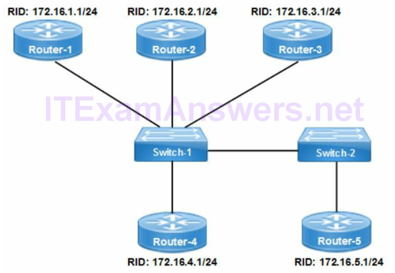
The highest IP address is calculated from left to right and based on IP address numbering. The numbers for each IP address match until octet 3 where subnet 4 is higher. That is the IP address assigned to Router-4.
- 172.16.1.1
- 172.16.2.1
- 172.16.3.1
- 172.16.4.1
Correct Answer: Router-4
Any OSPF enabled router with a priority of zero (0) cannot be elected as the designated router (DR) or BDR. The following command assigns a priority of zero (0) to a router.
router(config-if)# ip ospf priority 0
OSPF Operation
- The OSPF process ID is a unique number assigned to an OSPF routing instance. It is only locally significant to the router. The valid range for a process ID is 1 – 65,535. The routing instance includes a separate OSPF topology database for each process ID.
- Cisco supports multiple OSPF instances per router defined with a process identifier. It is similar to a VRF where a routing instance is created for a specific purpose such as partner connectivity. There is a maximum of 32 processes permitted per router. Any OSPF interface can only be assigned to a single process identifier.
- All OSPF routers send hello packets to neighbors on the same segment (subnet) using multicast 224.0.0.5 as the destination IP address.
- All areas must be connected directly to the backbone (area 0). The virtual link is not required where there is only a single area. It connects an area to the backbone area through an already connected area.
- The default hello timer interval for a multi-access (broadcast) network is 10 seconds. The dead timer is a default of 4 times the hello interval. Ethernet is an example of a multi-access network type.
- There is no maximum hop count for OSPF so it is unlimited.
- Passive interfaces prevent local router from sending hello message routing update on an interface to a non-OSPF neighbor. That provides security and minimize bandwidth utilization on links to non-OSPF neighbors.
Global Configuration
router(config)# router ospf [process id]
router(config-router)# network [ip address] [wildcard mask] area [number]
Verify OSPF
The following show commands verify OSPF operational status and layer 3 connectivity.
router# show ip ospf interfaces
router# show ip ospf neighbor
Troubleshooting OSPFv2
The following is a list of the most common causes of OSPF network errors. The result is no neighbor adjacency and as a result routes are not advertised.
- interfaces are shutdown
- area ID mismatch between neighbors
- hello and/or dead timer mismatch between neighbors
- OSPF network type mismatch between neighbors
- neighbor interfaces not assigned to the same subnet
- network command wildcard mask incorrect
- passive interface enabled on an interface
10. Configure, verify and troubleshoot single and multi-area OSPFv3
There is no requirement for OSPFv3 neighbors to share the same subnet to form an adjacency. OSPFv3 neighbor adjacency is established with link-local address. OSPFv3 routing is per link instead of per subnet with multiple instances per link support.
OSPFv2
- Assigned to a subnet
- Single IP address per interface
- IPv4 addressing only
- Multicast 224.0.0.5 (OSPF SPF routers) / 224.0.0.6 (DR/BDR)
OSPFv3
- Multiple IPv6 addresses per interface
- Adjacencies over link-local IP address
- IPv4 and IPv6 addressing
- FF02::5 (OSPF SPF routers) / FF02::6 (all DR/BDR routers)
OSPFv3 Configuration
The following assigns a global routable ipv6 address to an interface. The eui-64 keyword converts the address to modified format where the MAC address is used to create a unique interface id. The interface is assigned process ID 1 and area 0.
router(config)# interface gigabitethernet0/0
router(config-if)# no ip address
router(config-if)# ipv6 enable
router(config-if)# ipv6 address 2001:AB3E::/64 eui-64
router(config-if)# ospfv3 1 ipv6 area 0
11. Configure, verify and troubleshoot EIGRP for IPv4
Autonomous System (AS)
The single EIGRP autonomous system (AS) design simplifies routing significantly. The result is less router processing for a single EIGRP instance. The configuration is less complex and route propagation is automatic within a single AS. Route redistribution is required between multiple AS when deployed. EIGRP enabled routers can only advertises routes within the same autonomous system (AS). As a result the AS number assigned to each router must match.
Convergence
EIGRP is similar to OSPF where there is a routing table, neighbor table and topology table. Feasible successors are backup routes stored in the topology table.
Neighbor table = directly connected EIGRP neighbors
Topology table = routes learned from EIGRP neighbors including feasible successors.
Routing table = best (successor) routes selected from the EIGRP topology table.
The following table correctly describe the EIGRP route types available.
Table 4: EIGRP Route Types
| EIGRP Successor | best advertised route to a destination subnet. It is the route in the routing table |
| EIGRP AD | advertised cost from an EIGRP neighbor to the destination subnet |
| EIGRP Feasible Successor | backup route with advertised distance less than the feasible distance of the current successor route |
| EIGRP FD | advertised distance (cost) + cost between the local router and the next-hop router |
The following correctly describes EIGRP operation with default settings.
- EIGRP only uses a backup route if advertised distance (AD) is less than the feasible distance (FD)
- backup route selection rule prevents routing loops
- turn off auto summarization when classless subnet masks are configured.
Holddown Timer
EIGRP holddown timer affects how fast the network converges when there is a link failure. Each router interface enabled with EIGRP sends hello packets to its EIGRP neighbors. The default holddown timer value expires after three hello packets are not received from a neighbor. That is the time interval that EIGRP waits before declaring the neighbor unreachable. The local router notifies the neighbor that it is dropping the neighbor adjacency with a goodbye message.
Verify EIGRP Adjacency
The following command is used to confirm all established EIGRP adjacencies and IP addressing for the local router. It lists the active EIGRP neighbor adjacencies along with IP address and operational status. The smooth round trip time (SRTT), retransmit timeout setting (RTO) and queue count are included.
router# show ip eigrp neighbor
Troubleshooting EIGRP
The following is a list of the most common causes of EIGRP network errors. The result is EIGRP neighbor adjacencies are not formed and routes are not advertised.
- network interface is shutdown
- autonomous system mismatch between neighbors
- K values mismatch between neighbor interfaces
- neighbor interfaces are not assigned to the same subnet
- network command is missing subnet address or advertising incorrect subnet
- network command is configured with incorrect subnet mask
- passive interface enabled
The network interfaces on point-to-point link are not in the same subnet as required by EIGRP. As a result the routers won’t establish EIGRP neighbor adjacency.
12. Configure, verify and troubleshoot EIGRP for IPv6
EIGRP for IPv6 requires a router ID to be configured under the routing process.
The EIGRP router-id command is used when no IPv4 address is enabled.
The support for IPv6 addressing with EIGRP includes the following new features:
- EIGRP is configured per interface
- no support for network statements
- protocol instance is not enabled until the router ID is configured
13. Configure, verify and troubleshoot RIPv2 for IPv4
The primary enhancement to RIPv2 is support for classless subnets (CIDR). That enables advertisement of subnet mask length with routing advertisements.
RIPv2 routes use MD5 authentication between routers for optimized security.
RIPv2 sends routing table updates as a multicast to 224.0.0.9 instead of a broadcast used with RIPv1.
RIPv2 Configuration
The following commands will enable RIPv2 with classless routing
router(config)# router rip
router(config-router)# version 2
router(config-router)# network 172.16.0.0
router(config-router)# no auto-summary
Troubleshooting RIPv2
- interface is shutdown
- directly connected interfaces are not in same subnet
- network command has an incorrect subnet address or missing subnet
- no auto-summary command is not configured for classless routing
14. Troubleshoot Layer 3 end-to-end connectivity
Standard OSI model troubleshooting methodology:
1. Ethernet Cabling
2. Network Interface Card
3. IP Addressing
4. DNS Server
5. Application
The operational status of router interfaces can be verified with the following commands:
router# show interfaces
router# show ip interface brief
router# show protocols
Show IP Interface Brief
The IOS command show ip interface brief provides interface and line protocol status. That include all network interfaces with an assigned IP address. The Status column is layer 1 Ethernet signaling while the Protocol column is layer 2 data link connectivity.
The network interface status becomes “administratively down” when the network administrator configures the shutdown command. It is an interface level IOS command that manually changes the interface to down.
The show ip interface brief command displays any unconfigured interfaces as an unassigned IP address with status of down/down. The normal status is an assigned IP address with status of up/up.
router-1# show ip interface brief
Interface        IP address    OK   Method  Status     Protocol
FastEthernet0/0  172.16.1.1    YES  NVRAM   up         down
FastEthernet0/1  172.16.2.1    YES  Manual  up         up
Serial0/0        172.16.3.1    YES  Manual  up         up
Serial0/1        Unassigned    YES  Unset   admin down down
Loopback0        172.16.1.254  YES  NVRAM   up         up
The NVRAM status for GigabitEthernet0/0 indicates an interface change was made to the startup configuration file. For instance the IP address and subnet mask was assigned to the interface.
In addition the router was reloaded at some point after the configuration. The Manual status indicates some configuration change occurred and currently active however the router was not reloaded yet.
Host Addressing
The Windows command ipconfig /all is used for troubleshooting desktop connectivity issues. The output displays host IPv4/IPv6 addressing and that DHCP has assigned the default gateway. In addition the network administrator can verify the MAC address and operational status of all network adapters. Any issues with network connectivity from the client side can be confirmed.
Troubleshooting Host Connectivity
- incorrect default gateway
- incorrect subnet
- DHCP not enabled
- incorrect DNS server
Subnet Mismatch
Refer to the network topology drawing. What is the best explanation for why Host-1 cannot ping Server-1?
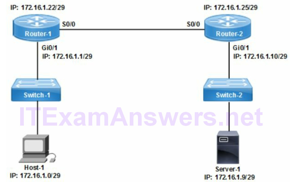
A. Host-1 and Server-1 are not on the same subnet
B. routing is not enabled on any switch
C. serial interfaces are assigned to different subnets
D. IP address of Server-1 is incorrect
Correct Answer (C)
The physical network interfaces for directly connected links must be assigned to the same subnet. That applies to LAN or WAN interfaces. The subnet mask and subnet within that range determines the subnet assigned to the network interface. The number of subnets available is based on the subnet mask length.
Router-1 = 172.16.1.22/29
Router-2 = 172.16.1.25/29
The /29 subnet mask assigns 29 bits to the network portion and 3 bits (23 = 8) to the host portion. The number of host addresses assignable = 6 (8 – 2). The network address (zero) and broadcast address (all ones) cannot be assigned.
network portion (/29) | hosts (3 bits = 6)
11111111.11111111.11111111.11111 000
- Router-1 = 172.16.1.22/29
- Network address = 172.16.1.16/29
- Broadcast address = 172.16.1.23/29
- Router-2 = 172.16.1.25/29
- Network address = 172.16.1.24/29
- Broadcast address = 172.16.1.31/29
- IP subnet range 1 = 172.16.1.16 – 172.16.1.23
- IP subnet range 2 = 172.16.1.24 – 172.16.1.31
The result is that Router-1 is within IP subnet range 1 while Router-2 is within IP subnet range 2. The serial interfaces are assigned to different subnets and can’t communicate. The ping is discarded and destination host unreachable is returned by Router-1.
Commands for troubleshooting layer 3 connectivity:
Table 5: Standard Layer 3 Troubleshooting Commands
| show interfaces | operational status, IP address, MAC address, MTU, bandwidth, interface errors |
| show ip interface brief | layer 1 and layer 2 interface status, all enabled interfaces |
| Ping | verify layer 3 reachability to a remote peer interface |
| show protocols | interface status, IP address and subnet mask |
| show running-config | verify the device configuration is correct |
ICMP destination host unreachable message is returned by a router to host. The message indicates that router cannot forward packets from that point. The cause could include physical (layer 1), encapsulation (layer 2), routing (layer 3) or ACL filtering.
