1. Troubleshoot client connectivity issues involving DNS
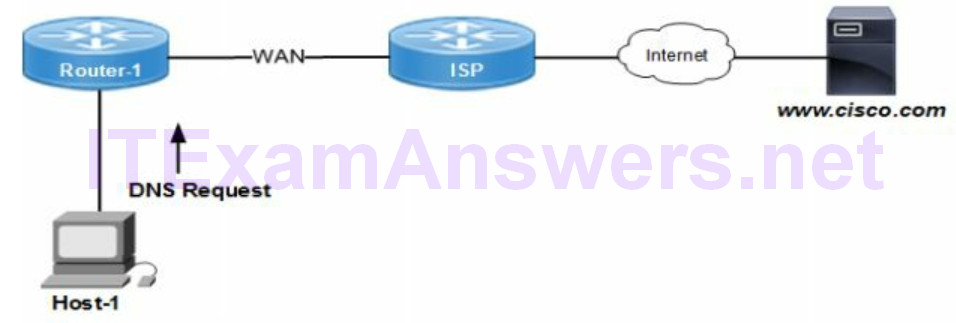
The IOS command ip name-server configures the DNS server IP address for a Cisco network device. All DNS queries are sent to the DNS server resolve the IP address from a hostname. That enables Telnet hopping that is based on a hostname between network devices.
DNS servers resolve a known IP address to an unknown hostname. In addition they can resolve a known hostname to an unknown IP address. Connecting to web servers for instance is based on a domain name.

The following techniques are used to verify the DNS server is reachable and hostname resolution is working properly.
- ping www.google.com (returns a request timed out error message if unavailable)
- nslookup www.google.com (verify IP address and domain name)
- nslookup 127.0.0.0 [dns server ip address] (host loopback to test DNS server)
2. Configure and verify DHCP on a router
DHCP Server Configuration
router(config)# ip dhcp pool [name]
router(dhcp-config)# network [ip address range]
router(dhcp-config)# dns-server [ip address]
router(dhcp-config)# default-router [ip address]
The default lease time for an IP address assigned from a Cisco based DHCP server is 1 day. The routers and switches would renew the IP address after 24 hours when triggered by a host request.
The network address and broadcast address should not be included with the DHCP pool for dynamic assignment. The host assignment would include anything else unless it is statically assigned already.
The host IP address renewal is based on the lease time setting. The host will typically keep using the same IP address assigned. The lease renewal request is sent to the DHCP server when the lease time expires. The DHCP server will extend the lease again for the lease time interval setting.

DHCP Relay
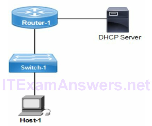
The IOS commands configure the DHCP relay agent for hosts on VLAN 10. There is support for assigning physical interfaces as well. The ip helper-address command is configured with the IP address of the DHCP server. All DHCP requests arriving from hosts are forwarded to the DHCP server (172.16.3.1) on a remote subnet. The DHCP relay agent is the router configured with the ip helper-address command.
router> enable
router# configure terminal
router(config)# interface vlan 10
router(config-if)# ip helper-address 172.16.3.1
Verify DHCP Bindings
DHCP binding table is comprised of entries with host IP address and MAC (hardware) address. That could include any network devices and servers configured as DHCP client. Cisco routers and switches can provide DHCP services to enabled hosts. The following IOS command lists the bindings for all DHCP enabled hosts.
router# show ip dhcp binding
IP Address   Hardware Address    Lease Expire          Type
172.16.1.1   0000.000a.aaaa      Aug 16 2017 17:00 PM  Auto
Troubleshooting DHCP
Layer 3 connectivity is verified with a ping of the DHCP server IP address. The cause of DHCP address assignment is often configuration errors on the DHCP server. In addition configuring DHCP server with the wrong DHCP relay address will cause errors.
DHCP uses Ping or Gratuitous ARP to detect IP address conflicts. The DHCP server will ping the proposed IP address to confirm it is not assigned. The ICMP echo reply is sent from any network device or host if it is already in use. The DHCP server will log the conflict error with a Syslog server. That is enabled with the ip dhcp conflict logging feature as a default.
Gratuitous ARP (GARP) is sent by a router as well to detect IP addresses in use. The network device would reply with an ARP to confirm IP address is not available. The DHCP server removes any IP address from the DHCP pool until conflicts are resolved.
router# show ip dhcp conflict
IP Address    Detection Method    Detection Time
172.16.1.32   Ping                July 16 2017 9:30 AM
172.16.1.64   Gratuitous ARP      July 16 2017 10:30 AM
The following command lists current DHCP pool status on the router. That includes the range of assigned IP addresses, number of leased addresses and any pending events. Misconfigured DHCP server causes various Layer 3 connectivity issues. That includes incorrect host subnet mask, default gateway address and DNS server address.
router# show ip dhcp pool
Utilization mark (high/low) : 100 / 0
Subnet size (first/next) : 0 / 0
Total addresses : 254
Leased addresses : 142
Pending event : none
1 subnet is currently in the pool:
Current index   IP address range         Leased addresses
10.10.1.1       10.10.1.1 - 10.10.1.254    142
Verify Host DHCP Settings
The host command to list all IP addressing is ipconfig /all. It provides the current TCP/IP settings including IP address, DHCP server and DNS server address. In addition MAC address and default gateway address can be verified.
The Windows desktop command ipconfig /release /renew will release the current IP address and request a new IP address. The DHCP server would assign a random IP address from the pool along with additional settings.
3. Troubleshoot client and router-based DHCP connectivity issues
The DHCP server is responsible for dynamic configuration of host IP settings. In addition it manages the renewal of new IP addresses from an address pool. DHCP address pool is defined on the DHCP server along with the lease time period. The DHCP address pool is a range of IP addresses reserved for dynamic assignment for hosts. The host could receive default gateway and DNS server addresses as well.
Host DHCP Request
The DHCP request for an IP address starts with server discovery. The DHCP server replies with an IP address lease offer. The host replies with an IP lease request for the proposed IP address. The DHCP server confirms the IP address with a lease acknowledgement to the host. The DHCP server will send the lease time and any additional address settings as well. The following are standard DHCP message types.
Step 1: Server Discovery = DHCPDISCOVERY
Step 2: IP Lease Offer = DHCPOFFER
Step 3: IP Lease Request = DHCPREQUEST
Step 4: IP Lease Acknowledgement = DHCPACK
4. Configure, verify and troubleshoot basic HSRP
HSRP Operation
HSRP advertises a virtual IP address to enable seamless failover to a standby router. The virtual router is based on a shared virtual IP address and MAC address. That enables redundancy for fast failover to the standby router.
The active HSRP active router is assigned the virtual IP address and MAC address for packet forwarding. The standby router is assigned the virtual addressing when the active router isn’t available. HSRP virtual IP address is the default gateway for hosts on the common subnet. VRRP is the open standard equivalent FHRP to HSRP.
The virtual IP address assigned to the HSRP group is configured on both router members with the standby 1 ip command. The group number and virtual IP address are assigned to the HSRP routers.
HSRP is not a routing protocol and virtual IP address is not installed in the routing table. It is a default gateway address where packets are forwarded for routing services.
Hello packets are sent between active and standby router at 3 second intervals by default to detect neighbor state. In addition the hold timer is 10 seconds.
The default HSRP values include the following settings:
Hello timer = 3 seconds
Hold timer = 10 seconds
Standby priority = 100
HSRP version = HSRPv1
Enabled groups = none
Default group = 0
HSRP Groups
The virtual MAC address for version 1 is 0000.0c07.ac01. This is for the group 1. The rightmost 2 bits (01) indicate the group number. The default HSRP group 0 would be assigned virtual MAC address 0000.0c07.ac00 for version 1.
There is support for assigning a maximum 255 groups per physical interfaces or VLAN interfaces. Multiple groups across multiple routers enable configuration of load balancing. At least one HSRP group is associated with at least two routers.
Priority Setting
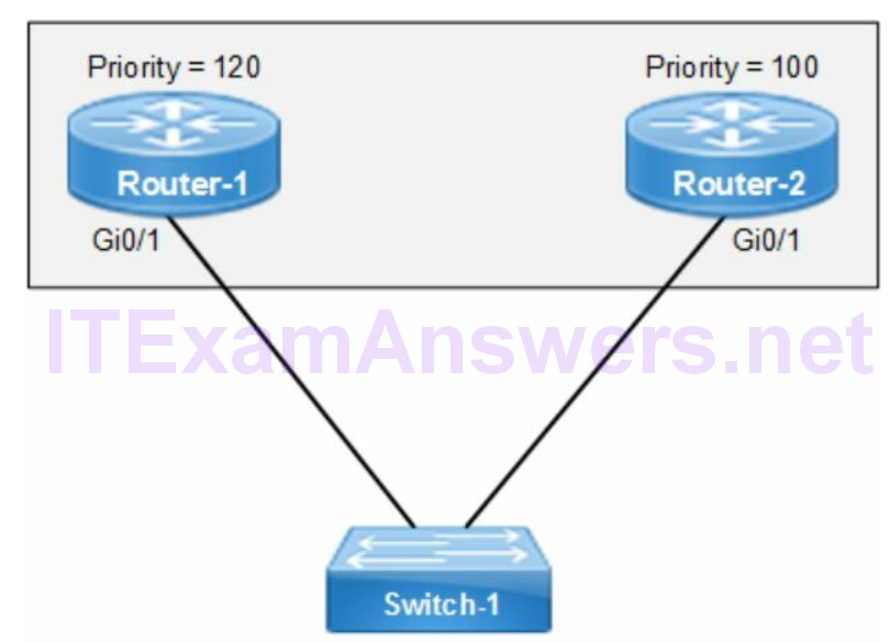
The default HSRP priority is 100. The active router is configured with a higher priority than standby router. The router with the highest IP address is elected the active router when all priorities are equal.
HSRP provides a tracking feature that detects when the active HSRP router is not available. That triggers a failover to the standby router. The priority of the active router is decremented by 10 as a default. The standby router has a higher priority and becomes the active router.

Preemption
The preempt command enables comparison of priority between routers to elect an active HSRP router. It is configured on all HSRP enabled routers so the router with highest priority becomes active. The following command configures a local interface as standby so that it becomes active when the current active router fails.
router(config-if)# standby 1 preempt
Version
The following are virtual MAC addresses based on the HSRP version.
- HSRPv1 = 0000.0c07.acxx
- HSRPv2 = 0000.0C9f.fxxx
- HSRP for IPv6 = 0005.73a0.0000 through 0005.73a0.0fff
HSRP version 2 sends hello messages to multicast 224.0.0.102 address. There are additional features supported with HSRPv2. The number of groups available with HSRPv2 is 4096 (0-4095) and IPv6 addressing is supported as well.
HSRP Configuration
router-1(config)# interface gigabitethernet0/1
router-1(config-if)# ip address 172.16.1.1 255.255.255.0
router-1(config-if)# standby version 2 (enables HSRPv2)
router-1(config-if)# standby 1 preempt (compare router priorities for group 1)
router-1(config-if)# standby 1 priority 110 (active router)
router-1(config-if)# standby 1 ip 172.16.1.3 (virtual IP address)
Verify HSRP
The following IOS command displays the HSRP operational status for all groups. The status includes active router, standby IP address, virtual addressing and timers.
router# show standby
Troubleshooting HSRP
The virtual IP address must be assigned from the same subnet as the router interfaces. All timers must match between HSRP router peers. The HSRP version must match between routers as well. There are features enabled with HSRPv2 not supported with HSRPv1. The VTP modes for both routers must match. The active router configured as VTP server requires the same VTP mode for standby.
HSRP States
The valid HSRP states from the list include Standby, Init and Active. In addition there is Listen and Speak states.
1. Initial (Init): This is the start state indicating that HSRP isn’t running.
2. Learn: The virtual IP address is unassigned and no hello message was received from the active router yet.
3. Listen: The virtual IP address and MAC address is known by the router. The active and standby router is unassigned. It listens for hello messages from HSRP enabled routers.
4. Speak: The router sends hello messages to elect active and standby router.
5. Standby: The router is in standby mode and monitors hello packets sent from the active router. It becomes active when active router fails.
6. Active: The router forwards packets to the HSRP group. In addition the active router sends regular hello packets.
5. Configure, verify and troubleshoot inside source NAT
Network Address Translation (NAT) translates private IP addressing to a public routable IP address for outbound internet traffic. The inbound traffic from the internet is translated (mapped) to a private IP address.
The following are primary advantages of NAT
- conceals private IP address assignments from the internet
- eases management of internet connectivity
The disadvantage to NAT is the IP address renumbering when switching internet service providers (ISP). The public routable (internet) IP address is used to configure translation for any static or dynamic NAT configuration.
Static NAT
The static NAT translation is a 1:1 configured mapping between local and global addresses. The static translation manually assigns a private IP address to a public IP address. For instance, three public routable IP addresses will allow three static NAT translations. As a result they are a permanent entry in the NAT translation table. They enable a remote host connection from an outside (external) network.
Dynamic Pool
Dynamic NAT pool mapping translates each private IP address to an available public IP address (1:1) in the NAT pool. The dynamic NAT pool of public IP addresses is shared by all internal IP addresses on a first come first served basis. The maximum number of simultaneous internet connections available is limited to the number of public IP addresses in the NAT pool.
Port Address Translation
Port Address Translation (PAT) is an IP address translation technique that translates the most internal (private) IP addresses to a single or multiple public IP addresses. It is an enhancement to NAT that assigns a unique source port number to each translated IP address. The host IP address for instance could be identified with 200.200.1.1:10 as the translated source IP address. The 10 is the unique source port making the translated IP address unique. The 16 bit source port field allows for translating 65,535 private (internal) IP addresses to a public IP address. There is support for a pool of addresses or single interface.
192.168.1.1:10 -> 200.200.1.1:10
192.168.1.2:11 -> 200.200.1.1:11
192.168.1.3:12 -> 200.200.1.1:12
The following IOS command enables Port Address Translation. The source list 1 points to ACL 1 that permits a range of internal (private) IP addresses to be translated. The [pool name] refers to a NAT pool that has a single or multiple public routable IP addresses assigned. The overload keyword enables port address translation of multiple internal IP private addresses to a single public IP address.
router(config)# ip nat inside source list 1 pool [pool name] overload
NAT Addressing
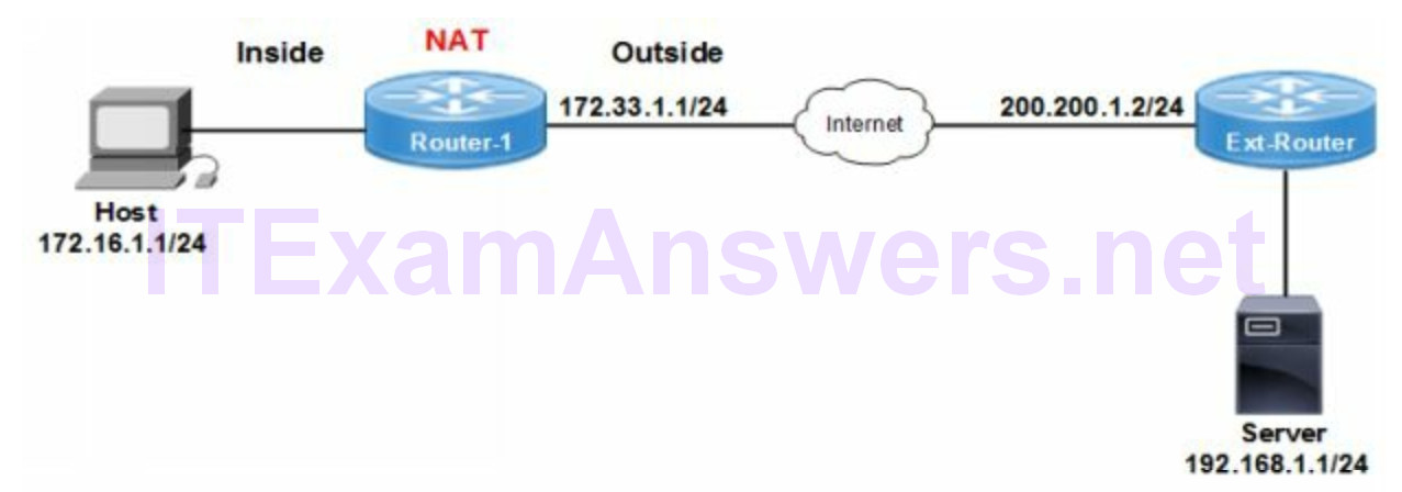
Inside Local IP Address (172.16.1.1/24)
Private IP address assigned to a host on the inside network (RFC 1918).
Inside Global IP Address (172.33.1.1/24)
Public internet routable IP address assigned by the ISP.
Outside Global IP Address (200.200.1.2/24)
Public internet routable IP address assigned to outside (remote) host device.
Outside Local IP Address (200.200.1.2/24)
Public internet routable IP address of outside host as appears to inside network.

NAT Configuration
The following configuration creates a NAT public pool of 10 public addresses. That is assigned for translating a range of private host addresses. In addition the overload feature is enabled for port address translation. The alternate to netmask keyword is prefix-length 28 that assigns the same /28 subnet mask (255.255.255.240).
1. Assign NAT inside interface
R1(config)# interface fastethernet2/0
R1(config-if)# ip nat inside
R1(config-if)# exit
2. Assign NAT outside interface
R1(config)# interface fastethernet1/0
R1(config-if)# ip nat outside
R1(config-if)# exit
3. Create a NAT pool cisco and assign ten public addresses from the range 172.33.1.1 to 172.33.1.10 (subnetting rules apply here)
R1(config)# ip nat pool cisco 172.33.1.1 172.33.1.10 netmask 255.255.255.240
4. Create access-list 1 to permit private host range 192.168.1.10 to
192.168.1.40
(wildcard mask rules apply here).
R1(config)# access-list 1 permit 192.168.1.9 0.0.0.7
5. Assign access control list 1 to the NAT pool and enable the overload feature.
R1(config)# ip nat inside source list 1 pool cisco overload
Verify NAT
The following command verifies network address translation is working correctly.
R1# show ip nat translations
6. Configure and verify NTP operating in client/server mode
The following table matches time source on the left with description on the right.
Table 1: Cisco Network Device Time Sources
| ntp peer | backup time server |
| system calendar | initializes software clock after restart |
| software clock | initially set by hardware clock |
| ntp server | external time server |
The following are all correct statements concerning NTP network protocol.
- provides time source for logging and time stamp transactions
- N+1 server redundancy (NTP master + NTP failover server)
- reference is UTC coordinated universal time
- DNS is required for resolving time server IP address
- stratum level is the distance from the NTP authoritative time source
The following statements correctly describe NTP operation:
- server mode routers provide time source to client mode devices
- time servers are hierarchical
- server mode routers poll an external time server
The ntp master command configures a network device as an NTP reference clock source. That is an alternative to an external authoritative time source and not recommended.
Configure NTP
The following IOS command configures an external time server as authoritative time source for a router.
router(config)# ntp server 172.16.1.1
Verify NTP
The following IOS commands are used to verify NTP server synchronization status, time source activities and stratum level for a router.
router# show ntp status
router# show ntp associations
