
Packet Tracer - Configuring and Verifying a Small Network
(Instructor Version)
Instructor Note: Red font color or Gray highlights indicate text that appears in the instructor copy only.
Topology
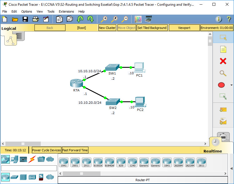
Addressing Table
| Device | Interface | IP Address | Subnet Mask | Default Gateway |
|---|---|---|---|---|
| RTA | G0/0 | 10.10.10.1 | 255.255.255.0 | N/A |
| G0/1 | 10.10.20.1 | 255.255.255.0 | N/A | |
| SW1 | VLAN1 | 10.10.10.2 | 255.255.255.0 | 10.10.10.1 |
| SW2 | VLAN1 | 10.10.20.2 | 255.255.255.0 | 10.10.20.1 |
| PC1 | NIC | 10.10.10.10 | 255.255.255.0 | 10.10.10.1 |
| PC2 | NIC | 10.10.20.10 | 255.255.255.0 | 10.10.20.1 |
Objectives
- Part 1: Configure Devices and Verify Connectivity
- Part 2: Gather Information with Show Commands
Background
In this activity, you will configure RTA with basic settings, including IP addressing. You will also configure SW1 for remote management and configure the PCs. Once you have successfully verified connectivity, you will use show commands to gather information about the network.
Note: The user EXEC password is cisco. The privileged EXEC password is class.
Part 1: Configure Devices and Verify Connectivity
Step 1: Apply basic configurations to RTA.
a. Using the following information and the Addressing Table, configure RTA:
- Hostname and banner
- Line passwords set to cisco; encrypted password set to class
- IP addressing and descriptions on LAN interfaces
b. Save the configuration.
Router> enable
Router# configure terminal
Router(config)# hostname RTA
RTA(config)# banner motd #This is RTA router#
RTA(config)# line console 0
RTA(config-line)# password cisco
RTA(config-line)# login

RTA(config-line)# line vty 0 15
RTA(config-line)# password cisco
RTA(config-line)# login
RTA(config-line)# exit

RTA(config)# enable secret class

RTA(config)# interface gigabitethernet 0/0
RTA(config-if)# description Link to SW1 - LAN 10.10.10.0/24
RTA(config-if)# ip address 10.10.10.1 255.255.255.0
RTA(config-if)# no shutdown

RTA(config-if)# interface gigabitethernet 0/1
RTA(config-if)# description Link to SW2 - LAN 10.10.20.0/24
RTA(config-if)# ip address 10.10.20.1 255.255.255.0
RTA(config-if)# no shutdown

RTA(config-if)# end
RTA# copy running-config startup-config
Step 2: Configure addressing on PC1 and PC2.
a. Using the Addressing Table, configure IP addressing for PC1 and PC2.
b. Test connectivity between PC1 and PC2. Troubleshoot as necessary.
Step 3: Configure SW1 for remote management.
a. Using the Addressing Table, configure the management interface for SW1.
b. Configure the default gateway address.
c. Save the configuration.
SW1> enable
SW1# configure terminal
SW1(config)# interface vlan 1
SW1(config-if)# ip address 10.10.10.2 255.255.255.0
SW1(config-if)# no shutdown
SW1(config-if)# exit

SW1(config)# ip default-gateway 10.10.10.1

SW1(config)# end
SW1# copy running-config startup-config
Part 2: Gather Information with Show Commands
Step 1: Gather information from show interface command output.
Issue each of the following commands and then answer the related questions:
show ip interface brief
show interfaces
show ip interface
Which commands display the status of the port?
show ip interface brief
show interfaces
show ip interface
Which command shows only the IP address (no subnet mask or prefix)?
show ip interface briefWhich command displays the description configured on the interface?
show interfacesWhich command displays the IP broadcast address?
show interfacesWhich command displays the MAC address of the interface?
show interfacesStep 2: Gather information from show ip route command output.
Issue each of the following commands and then answer the related questions:
show ip route
show ip route connected
How many networks are known by the router based on the output of the show ip route command?
2 - 10.10.10.0/24 & 10.10.20.0/24What does the L at the beginning of the lines within the routing table represent?
Local connection
What does the /32 prefix listed in the route table indicate?
The host address of the interface
Step 3: Gather information after an interface state is changed.
a. On RTA, shut down the Gigabit Ethernet 0/0 interface and issue the show ip route command. How many networks are displayed in the routing table now?
1 - 10.10.20.0/24
b. Attempt to ping PC1. Was the ping successful?
No
c. Issue the show ip interface brief command. What is the status of the Gigabit Ethernet 0/0 interface?
administratively down
d. Reactivate the Gigabit Ethernet 0/0 interface. Issue the show ip route command. Did the routing table repopulate?
Yes
What can be inferred about the interface status of routes that appear in the routing table?
Interfaces must be active in order to be listed in the routing table.
Device Configs - Final
ROUTER RTA
! ==============================================================
!--- 1.1.4.5 Packet Tracer - Configuring and Verifying a Small Network
!--- ANSWER SCRIPT FOR ROUTER RTA
!--- Usage: copy this whole file and paste it into the Router terminal (start at the Router> prompt). Every line beginning with "!" is a comment; IOS ignores it, so pasting a comment by accident is harmless.
! ==============================================================

enable
configure terminal

! --------------------------------------------------------------
!--- Part 1, Step 1: Apply basic configurations to RTA.
! --------------------------------------------------------------

!--- Assign the hostname.
hostname RTA

!--- Configure the message-of-the-day banner.
banner motd #This is RTA router#

!--- Set the console line password to cisco and require login.
line console 0
 password cisco
 login
 exit

!--- Set the VTY line password to cisco and require login.
line vty 0 15
 password cisco
 login
 exit

!--- Set the encrypted privileged EXEC password to class.
enable secret class

!--- G0/0 - LAN interface toward SW1 / PC1 (10.10.10.1/24), with a description.
interface gigabitethernet 0/0
 description Link to SW1 - LAN 10.10.10.0/24
 ip address 10.10.10.1 255.255.255.0
 no shutdown
 exit

!--- G0/1 - LAN interface toward SW2 / PC2 (10.10.20.1/24), with a description.
interface gigabitethernet 0/1
 description Link to SW2 - LAN 10.10.20.0/24
 ip address 10.10.20.1 255.255.255.0
 no shutdown
 exit

end

! --------------------------------------------------------------
!--- Save the configuration to NVRAM. (Press Enter when prompted for the destination filename.)
! --------------------------------------------------------------
copy running-config startup-config


! ==============================================================
!--- Verification:
!---   show ip interface brief    -> G0/0 and G0/1 up/up with the correct IPv4 addresses
!---   show interfaces            -> descriptions, MAC addresses and port status of each interface
!---   show ip route connected    -> 10.10.10.0/24 and 10.10.20.0/24 as C routes, plus /32 L routes
!---   ping 10.10.10.10           -> RTA reaches PC1
!---   ping 10.10.20.10           -> RTA reaches PC2
!--- Note: Part 2 Step 3 asks you to shut down G0/0 and then reactivate it.
!--- Remember to run "no shutdown" on G0/0 again, otherwise PC1 stays
!--- unreachable and the Packet Tracer score drops.
! ==============================================================
SWITCH SW1
! ==============================================================
!--- 1.1.4.5 Packet Tracer - Configuring and Verifying a Small Network
!--- ANSWER SCRIPT FOR SWITCH SW1
!--- Usage: log in to SW1 (user EXEC password: cisco), type "enable" and enter the privileged EXEC password "class", then copy this whole file and paste it at the SW1# prompt. Every line beginning with "!" is a comment; IOS ignores it, so pasting a comment by accident is harmless.
! ==============================================================

enable
configure terminal

! --------------------------------------------------------------
!--- Part 1, Step 3: Configure SW1 for remote management.
! --------------------------------------------------------------

!--- Configure the management interface (VLAN 1) with 10.10.10.2/24.
interface vlan 1
 ip address 10.10.10.2 255.255.255.0
 no shutdown
 exit

!--- Configure the default gateway address (RTA G0/0).
ip default-gateway 10.10.10.1

end

! --------------------------------------------------------------
!--- Save the configuration to NVRAM. (Press Enter when prompted for the destination filename.)
! --------------------------------------------------------------
copy running-config startup-config


! ==============================================================
!--- Verification:
!---   show ip interface brief  -> Vlan1 up/up with 10.10.10.2
!---   show running-config      -> "ip default-gateway 10.10.10.1" is present
!---   ping 10.10.10.1          -> SW1 reaches its gateway (RTA G0/0)
!---   ping 10.10.20.10         -> SW1 reaches PC2 in the other subnet through RTA
!--- Note: the ping to 10.10.20.10 only works once the default gateway is set;
!--- without it SW1 can reach its own subnet only.
! ==============================================================
PC1
PC2
Download Packet Tracer (.pka) file:

