2.2.3 Packet Tracer – Configure Ethernet Interfaces for IP on Hosts and Routers Answers
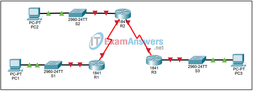
Topology

| Device | Interface | IP Address | Subnet Mask | Default Gateway |
|---|---|---|---|---|
| R1 | Fa0/0 | 172.16.3.1 | 255.255.255.0 | N/A |
| S0/0 | 172.16.2.1 | 255.255.255.0 | N/A | |
| R2 | Fa0/0 | 172.16.1.1 | 255.255.255.0 | N/A |
| S0/0 | 172.16.2.2 | 255.255.255.0 | N/A | |
| S0/1 | 192.168.1.2 | 255.255.255.0 | N/A | |
| R3 | Fa0/0 | 192.168.2.1 | 255.255.255.0 | N/A |
| S0/0 | 192.168.1.1 | 255.255.255.0 | N/A | |
| PC1 | NIC | 172.16.3.10 | 255.255.255.0 | 172.16.3.1 |
| PC2 | NIC | 172.16.1.10 | 255.255.255.0 | 172.16.1.1 |
| PC3 | NIC | 192.168.2.10 | 255.255.255.0 | 192.168.2.1 |
Introduction:
Ethernet is the dominant Layer 2 technology used in LANs. To enable communication, the Ethernet interfaces on hosts are configured with IP information. Router Ethernet interfaces are also configured with IP information to allow them to communicate with the hosts in an attached LAN.
Learning Objectives:
- Configure IP information on Ethernet interfaces in a network.
- Configure IP information on PCs.
- Configure IP information on router Ethernet interfaces.
- Verify proper operation.
- Verify interface status on the routers.
- Verify connectivity between hosts and routers.
- Observe ARP operation.
Task 1: Configure IP information on Ethernet interfaces in a network.
Step 1 – Configure IP information on PCs.
Configure the following IP information on the three network PCs:
- PC1 – IP Address: 172.16.3.10, Subnet Mask: 255.255.255.0, Gateway:172.16.3.1
- PC2 – IP Address: 172.16.1.10, Subnet Mask: 255.255.255.0, Gateway:172.16.1.1
- PC3 – IP Address: 192.168.2.10, Subnet Mask: 255.255.255.0, Gateway:192.168.2.1
Step 2 – Configure IP information on router Ethernet interfaces.
Access router R1. From the CLI tab, enter privileged exec mode by issuing the enable command. Enter global configuration mode by issuing the command config t. Enter configuration mode for the first FastEthernet interface by issuing the command interface fa0/0. Configure the IP address by issuing the command ip address 172.16.3.1 255.255.255.0. Activate the interface by issuing the command no shutdown. Exit configuration mode by using Ctrl+z. Save the configuration by issuing the command copy run start. Repeat the steps for the other two routers using the following information:
- R2 – IP Address: 172.16.1.1, Subnet Mask: 255.255.255.0
- R3 – IP Address: 192.168.2.1, Subnet Mask: 255.255.255.0
Task 2: Verify proper operation.
Step 1 – Verify interface status on the routers.
On each of the three routers, verify the status of the FastEthernet interfaces by issuing the command show ip interface brief.
Step 2 – Verify connectivity between hosts and routers.
From the PC1 command prompt, issue the command arp -a. On router R1, issue the command show arp. Note the results. From the PC1 command prompt, issue the command ping 172.16.3.1. From the PC1 command prompt, issue the command arp -a. On router R1, issue the command show arp. Note the results. Both devices now have an entry for the other in their ARP table.
Step 3 – Observe ARP operation.
Change to simulation mode. Set the Event List Filters to show only ARP and ICMP events. From the PC2 command prompt, issue the command ping 172.16.1.1. Minimize the command prompt window. Click the Auto Capture / Play button. Notice that ARP packets are sent before the ICMP packets.
