2.1.3 Packet Tracer – Build the Chapter Topology Answers
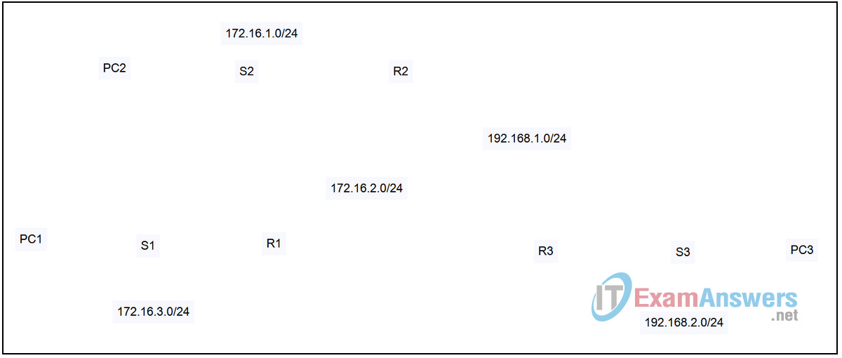
Topology

| Device | Interface | IP Address | Subnet Mask | Default Gateway |
|---|---|---|---|---|
| R1 | Fa0/0 | 172.16.3.1 | 255.255.255.0 | N/A |
| S0/0/0 | 172.16.2.1 | 255.255.255.0 | N/A | |
| R2 | Fa0/0 | 172.16.1.1 | 255.255.255.0 | N/A |
| S0/0/0 | 172.16.2.2 | 255.255.255.0 | N/A | |
| S0/0/1 | 192.168.1.2 | 255.255.255.0 | N/A | |
| R3 | Fa0/0 | 192.168.2.1 | 255.255.255.0 | N/A |
| S0/0/1 | 192.168.1.1 | 255.255.255.0 | N/A | |
| PC1 | NIC | 172.16.3.10 | 255.255.255.0 | 172.16.3.1 |
| PC2 | NIC | 172.16.1.10 | 255.255.255.0 | 172.16.1.1 |
| PC3 | NIC | 192.168.2.10 | 255.255.255.0 | 192.168.2.1 |
Introduction:
In this activity, we will place the devices in the chapter topology, install modules in the routers, configure display names for the devices, and connect the devices using the proper cables.
Learning Objectives:
- Place and physically configure the devices.
- Place the devices in the topology.
- Add modules to the routers.
- Name the devices.
- Change the device display names.
- Connect the devices.
- Connect the routers to each other.
- Connect the LANs.
Task 1: Place and physically configure the devices.
Step 1 – Place the devices in the topology.
- Drag three 1841 routers from the device area to the logical workplace and place them on top of labels R1, R2, and R3.
- Drag three 2960 switches from the device area to the logical workplace and place them on top of labels S1, S2, and S3.
- Drag three generic PCs from the device area to the logical workplace and place them on top of labels PC1, PC2, and PC3.
Step 2 – Add modules to the routers.
For each of the three routers:
- Click on the router. The router configuration window opens with the Physical tab selected. Click the power switch to turn off the router.
- Drag a WIC-2T module to the open slot on the right.
- Turn the router back on and click the CLI tab to view to boot up process. When the boot up process is complete, click the Config tab.
Task 2: Name the devices.
Step 1 – Change the device display names.
- Access router R1. The router configuration window opens with the Config tab selected. Set the Display Name to R1.
- Change the display names on the other two routers to match the labels.
- Change the display names on the three switches to match the labels.
- Change the display names on the three PCs to match the labels. To avoid name conflicts, change the display name of PC3 first followed by PC2 then PC1.
Task 3: Connect the devices.
Step 1 – Connect the routers to each other.
- Select connections in the device area and use a serial DCE cable to connect interface Serial0/0/0 on router R1 to interface Serial0/0/0 on router R2. The first router you click is connected to the DCE end of the cable, so start with router R1.
- Use a serial DCE cable to connect interface Serial0/0/1 on router R2 to interface Serial0/0/1 on router R3. The first router you click is connected to the DCE end of the cable, so start with router R2.
Step 2 – Connect the LANs.
- Use a copper straight-through cable to connect interface FastEthernet0/0 on all three routers to the first port on the corresponding switch.
- Use a copper straight-through cable to connect the FastEthernet interface on all three PCs to the next port on the corresponding switch.
Step 3 – Verify the configuration.
Verify your configuration by clicking the Check Result button.
