6.4.2 Packet Tracer – Troubleshooting a VLSM Addressing Design Answers
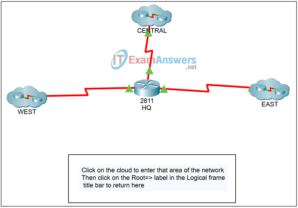
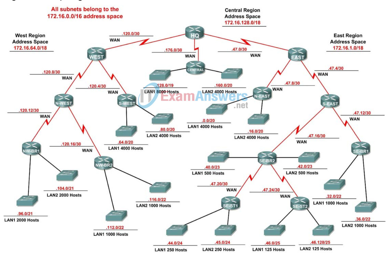
Topology


NOTE TO USER: Do not configure the routers until you reach Task 7.
Addressing Table
This activity does not include an addressing table.
Learning Objectives
- Determine the number of subnets needed.
- Determine the number of hosts needed for each subnet.
- Design an appropriate addressing scheme using VLSM.
Introduction:
In this activity, you have been given the network address 172.16.0.0/16 to subnet and provide the IP addressing for the network shown in the Topology Diagram. VLSM will be used so that the addressing requirements can be met using the 172.16.0.0/16 network.
The network has the following addressing requirements:
East Network Section
- The NE (Northeast) LAN1 will require 4000 host IP addresses.
- The NE (Northeast) LAN2 will require 4000 host IP addresses.
- The SE-BR1 (Southeast Branch1) LAN1 will require 1000 host IP addresses.
- The SE-BR1 (Southeast Branch1) LAN2 will require 1000 host IP addresses.
- The SE-BR2 (Southeast Branch2) LAN1 will require 500 host IP addresses.
- The SE-BR2 (Southeast Branch2) LAN2 will require 500 host IP addresses.
- The SE-ST1 (Southeast Satellite1) LAN1 will require 250 host IP addresses.
- The SE-ST1 (Southeast Satellite1) LAN2 will require 250 host IP addresses.
- The SE-ST2 (Southeast Satellite2) LAN1 will require 125 host IP addresses.
- The SE-ST2 (Southeast Satellite2) LAN2 will require 125 host IP addresses.
West Network Section
- The SW (Southwest) LAN1 will require 4000 host IP addresses.
- The SW (Southwest) LAN2 will require 4000 host IP addresses.
- The NW-BR1 (Northwest Branch1) LAN2 will require 2000 host IP addresses.
- The NW-BR1 (Northwest Branch1) LAN1 will require 2000 host IP addresses.
- The NW-BR2 (Northwest Branch2) LAN1 will require 200 host IP addresses.
- The NW-BR2 (Northwest Branch2) LAN2 will require 200 host IP addresses.
Central Network Section
- The Cent (Central) LAN1 will require 8000 host IP addresses.
- The Cent (Central) LAN2 will require 4000 host IP addresses.
The WAN links between each of the routers will require an IP address for each end of the link.
Task 1: Examine the Network Requirements.
Examine the network requirements and answer the questions below. Keep in mind that IP addresses will be needed for each of the LAN interfaces.
1. How many LAN subnets are needed? _18_
2. How many subnets are needed for the WAN links between routers? _13_
3. How many total subnets are needed? _31_
4. What is the maximum number of host IP addresses that are needed for a single subnet? _8.000_
5. What is the least number of host IP addresses that are needed for a single subnet? _125_
6. How many IP addresses are needed for the HQ portion of the network? Be sure to include the WAN links as well as an IP address for each LAN interface. __
7. How many IP addresses are needed for the East portion of the network? Be sure to include the WAN links as well as an IP address for each LAN interface. _11.764_
8. How many IP addresses are needed for the West portion of the network? Be sure to include the WAN links as well as an IP address for each LAN interface. _10.410_
9. How many IP addresses are needed for the Central portion of the network? Be sure to include the WAN links as well as an IP address for each LAN interface. _ 12.002_
10. What is the total number of IP addresses that are needed? _ 34.176_
11. What is the total number of IP addresses that are available in the 172.16.0.0/16 network? _65.534_
12. Can the network addressing requirements be met using the 172.16.0.0/16 network? _yes_
Task 2: Divide the total Network into four equal Subnetworks.
Step 1. Assign the subnetworks as shown here
- HQ receives the first subnet
- Central receives the second subnet
- East receives the third subnet
- West receives the fourth subnet
Task 3: Design an IP Addressing Scheme for the HQ Network.
Use the last 256 addresses of the assigned subnet to create subnetworks for the WAN links
Step 1. Determine the subnet for the WAN links
The subnet for HQ is 172.16.0.0 to 172 16.63.255
The last 256 addresses should start with the 172.16.63.0 address.
Step 2. Assign the first subnet to the WAN link from HQ to CENTRAL.
Step 3. Assign the first subnet to the WAN link from HQ to EAST.
Step 4. Assign the first subnet to the WAN link from HQ to WEST.
Task 4: Design an IP Addressing Scheme for the Central Network.
NOTE TO USER: There is no need to calculate for future growth of the networks in this activity.
Step 1. Determine and assign the subnet information for the Central LAN1.
Step 2. Determine and assign the subnet information for the Central LAN2.
There are no WAN subnets needed for the Central area.
Task 5: Design an IP Addressing Scheme for the EAST Network.
Step 1. Determine and assign the subnet information for the NE LAN1.
Step 2. Determine and assign the subnet information for the NE LAN2.
Step 3. Determine and assign the subnet information for the SE-BR1 LAN1.
Step 4. Determine and assign the subnet information for the SE-BR1 LAN2.
Step 5. Determine and assign the subnet information for the SE-BR2 LAN1.
Step 6. Determine and assign the subnet information for the SE-BR2 LAN2.
Step 7. Determine and assign the subnet information for the SE-ST1 LAN1.
Step 8. Determine and assign the subnet information for the SE-ST1 LAN2.
Step 9. Determine and assign the subnet information for the SE-ST2 LAN1.
Step 10. Determine and assign the subnet information for the SE-ST2 LAN2.
Use the last 256 addresses of the EAST assigned subnet to create subnetworks for the WAN links
Step 11. Determine the subnet information for the WAN links in the EAST network.
Step 12. Assign the first subnet to the WAN link from EAST to NE.
Step 13. Assign the first subnet to the WAN link from EAST to SE.
Step 14. Assign the first subnet to the WAN link from SE to SE-BR1.
Step 15. Assign the first subnet to the WAN link from SE to SE-BR2.
Step 16. Assign the first subnet to the WAN link from SE-BR2 to SE-ST1.
Step 17. Assign the first subnet to the WAN link from SE-BR2 to SE-ST2.
Task 6: Design an IP Addressing Scheme for the WEST network.
Step 1. Determine and assign the subnet information for the SW LAN1.
Step 2. Determine and assign the subnet information for the SW LAN2.
Step 3 Determine and assign the subnet information for the NW-BR1 LAN1.
Step 4. Determine and assign the subnet information for the NW-BR1 LAN2.
Step 5. Determine and assign the subnet information for the NW-BR2 LAN1.
Step 6. Determine and assign the subnet information for the NW-BR2 LAN2.
Use the last 256 addresses of the WEST assigned subnet to create subnetworks for the WAN links
Step 7. Determine the subnet information for the WAN links between the routers in the West network.
Step 8. Assign the first subnet to the WAN link from WEST to SW.
Step 9. Assign the first subnet to the WAN link from WEST to NW.
Step 10. Assign the first subnet to the WAN link from NW to NW-BR1.
Step 11. Assign the first subnet to the WAN link from NW to NW-BR2.
Task 7: Assign IP addresses throughout the network
Step 1. Using the information gathered in the previous tasks assign addresses to each router.
Step 2. Serial interfaces that have the DCE connection should receive the first IP address of a subnet.
Step 3. The gateway interface for any network should be the first IP address in the subnet.
All configuration except for the ip addressing has been done including configuring RIP v2 routing, so to test your scheme you should be able to ping from any one of the interfaces to another.
