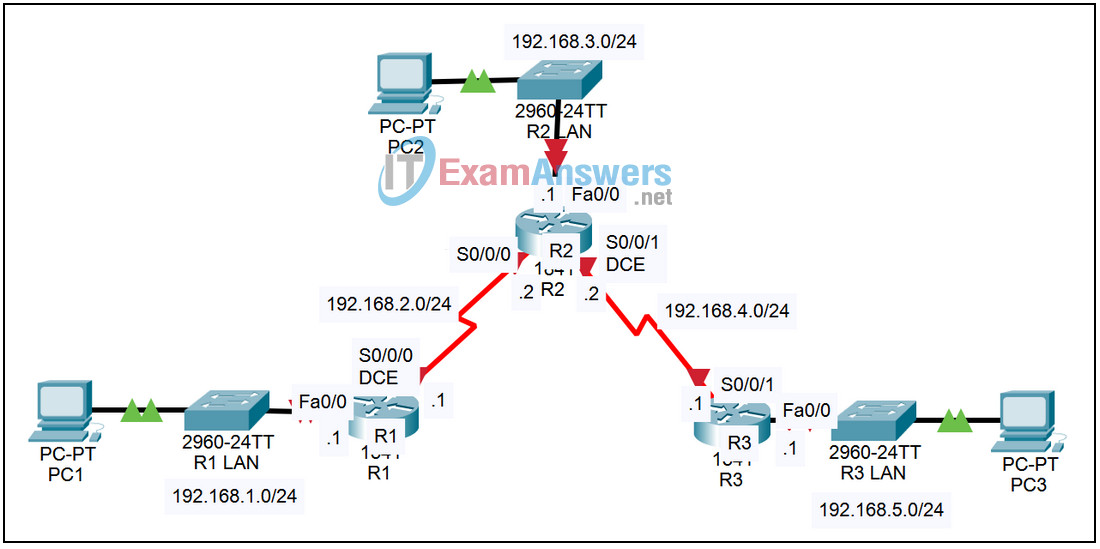
5.2.1 Packet Tracer – Configure IP Addresses on Router Interfaces Answers
Topology

| Device | Interface | IP Address | Subnet Mask | Default Gateway |
|---|---|---|---|---|
| R1 | Fa0/0 | 192.168.1.1 | 255.255.255.0 | N/A |
| S0/0/0 | 192.168.2.1 | 255.255.255.0 | N/A | |
| R2 | Fa0/0 | 192.168.3.1 | 255.255.255.0 | N/A |
| S0/0/0 | 192.168.2.2 | 255.255.255.0 | N/A | |
| S0/0/1 | 192.168.4.2 | 255.255.255.0 | N/A | |
| R3 | Fa0/0 | 192.168.5.1 | 255.255.255.0 | N/A |
| S0/0/1 | 192.168.4.1 | 255.255.255.0 | N/A | |
| PC1 | NIC | 192.168.1.10 | 255.255.255.0 | 192.168.1.1 |
| PC2 | NIC | 192.168.3.10 | 255.255.255.0 | 192.168.3.1 |
| PC3 | NIC | 192.168.5.10 | 255.255.255.0 | 192.168.5.1 |
Introduction:
The first step toward enabling a router to forward IP packets is to configure IP information on the interfaces. This configuration provides access to directly connected networks.
Learning Objectives:
- Configure IP information on routers.
- Verify the configuration.
- Verify Layer 1 and Layer 2 information.
- Examine the IP routing table.
Task 1: Configure IP information on routers.
Step 1 – Access router R1 and enter global configuration mode.
From the CLI tab, enter the privileged exec mode by issuing the enable command. Enter the global configuration mode by issuing the command config t.
Step 2 – Configure interfaces.
- Enter the configuration mode for the first FastEthernet interface by issuing the command interface fa0/0.
- Configure the IP address by issuing the command ip address 192.168.1.1 255.255.255.0 and activate the interface with the no shutdown command.
- Enter the configuration mode for the first Serial interface by issuing the command interface s0/0/0.
- Configure the IP address by issuing the command ip address 192.168.2.1 255.255.255.0.
- Configure the clock rate with the clock rate 64000 command and activate the interface.
Step 3 – Save the configuration.
Exit the configuration mode by hitting Ctrl+z. Save the configuration by issuing the command copy run start.
Step 4 – Configure routers R2 and R3.
Repeat Steps 1 through 3 for the other two routers using the information in the table above.
Task 2: Verify the configuration.
Step 1 – Verify Layer 1 and Layer 2 information.
On each of the three routers, verify the status of the interfaces by issuing the command show ip interface brief. Verify the IP address on all of the interfaces and that the interfaces are up and the line protocol is up.
Step 2 – Examine the IP routing table.
On each of the three routers, examine the IP routing table by issuing the command show ip route. Notice that the routing table contains information only about directly connected networks.
