8.4.1 Lab – Investigating the Routing Table Lookup Process Answers
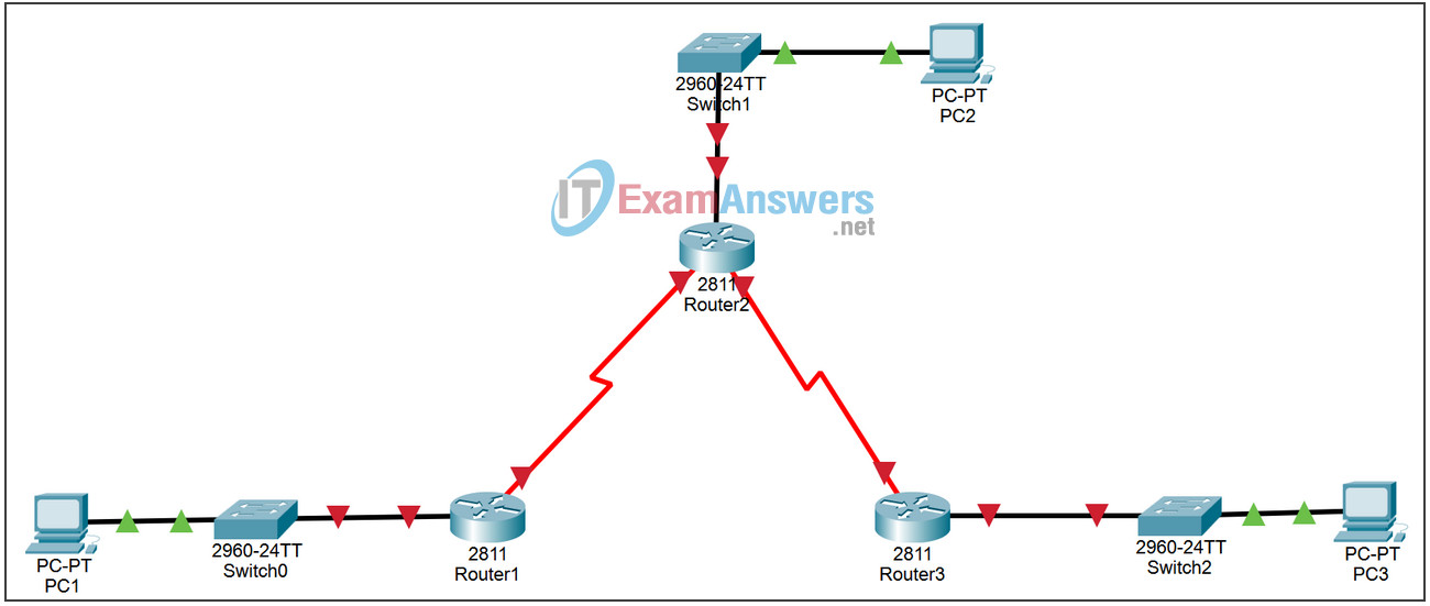
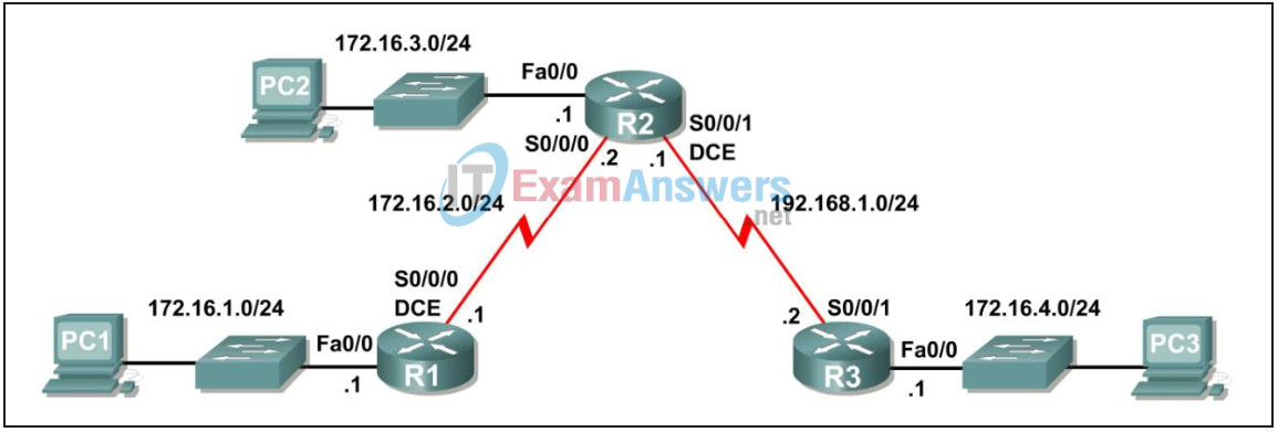
Topology


Addressing Scheme:
| Device | Interface | IP Address | Subnet Mask | Default Gateway |
|---|---|---|---|---|
| R1 | Fa0/0 | 172.16.1.1 | 255.255.255.0 | N/A |
| S0/0/0 | 172.16.2.1 | 255.255.255.0 | N/A | |
| R2 | Fa0/0 | 172.16.3.1 | 255.255.255.0 | N/A |
| S0/0/0 | 172.16.2.2 | 255.255.255.0 | N/A | |
| S0/0/1 | 192.168.1.1 | 255.255.255.0 | N/A | |
| R3 | Fa0/0 | 172.16.4.1 | 255.255.255.0 | N/A |
| S0/0/1 | 192.168.1.2 | 255.255.255.0 | N/A | |
| PC1 | NIC | 172.16.1.10 | 255.255.255.0 | 172.16.1.1 |
| PC2 | NIC | 172.16.3.10 | 255.255.255.0 | 172.16.3.1 |
| PC3 | NIC | 172.16.4.10 | 255.255.255.0 | 172.16.4.1 |
Learning Objectives:
- Perform basic configuration tasks on a router.
- Determine level 1 and level 2 routes.
- Modify the configuration to reflect static and default routing.
- Enable classful routing and investigate classful routing behavior.
- Enable classless routing and investigate classless routing behavior.
Task 1: Network preparation.
Step 1: Connect a network that is similar to the one in the Topology Diagram.
You can use any router you currently have in your lab, as long as it has the necessary interfaces shown in the topology.
Note: If you use 1700, 2500, or 2600 routers, the results and router descriptions will appear differently.
Step 2: Delete all configurations that the routers have.
Task 2: Perform basic router configurations.
Perform basic configurations of routers R1, R2, and R3 according to the following general guidelines:
1. Configure the hostname of the router.
2. Disable DNS lookup.
3. Set an EXEC mode password.
4. Set a message of the day.
5. Set a password for console connections.
6. Set a password for VTY connections.
Task 3: Configuration and activation of serial and Ethernet addresses.
Step 1: Configure the interfaces of R1, R2 and R3.
Configure the interfaces of routers R1, R2, and R3 with the IP addresses from the table below the Topology Diagram.
Step 2: Verify IP addressing and interfaces.
Use the show ip interface brief command to verify that IP addressing is correct and that the interfaces are up.
When you are finished, be sure to save the running configuration to the router’s NVRAM.
Step 3: Configure the Ethernet interfaces of PC1, PC2 and PC3.
Configure the Ethernet interfaces of PC1, PC2, and PC3 with the default IP addresses and gateways from the table below the Topology Diagram.
Step 4: Test the PC configuration by executing a ping from the PC to the default gateway.
Task 4: Configure the RIP protocol.
Configure RIP routing, version 1, on each of the routers. Include network statements for each of the directly connected networks.
Task 5: Observe the routes that are deleted and added to the routing table.
Step 1: View the routing table on router R1.
What networks are shown in the routing table?
172.16.0.0/24
172.16.1.0
172.16.2.0
172.16.3.0
192.168.1.0/24
Step 2: Use the debug ip routing command to observe changes to the routing table as they occur on router R1.
R1#debug ip routing
IP routing debugging is on
Step 3: Shut down the Serial0/0/0 interface and observe the debug output.
R1(config-if)#shutdown

%LINK-5-CHANGED: Interface Serial0/0/0, changed state to administratively
down
RT: interface Serial0/0/0 removed from routing table
%LINEPROTO-5-UPDOWN: Line protocol on Interface Serial0/0/0, changed state to
down
RT: del 172.16.2.0 via 0.0.0.0, connected metric [0/0]
RT: delete network route to 172.16.2.0
RT: NET-RED 172.16.2.0/24
RT: del 172.16.3.0 via 172.16.2.2, rip metric [120/1]
RT: delete network route to 172.16.3.0
RT: NET-RED 172.16.3.0/24
RT: del 192.168.1.0 via 172.16.2.2, rip metric [120/1]
RT: delete network route to 192.168.1.0
RT: NET-RED 192.168.1.0/24
Step 4: View the routing table of router R1 and note the changes that occurred when the Serial0/0/0 interface was disabled.
R1#show ip route
<Output omitted>

Gateway of last resort is not set

     172.16.0.0/24 is subnetted, 1 subnets
C       172.16.1.0 is directly connected, FastEthernet0/0
R1#
Step 5: Enable the Serial0/0/0 interface and observe the debug output.
R1(config-if)#no shutdown

RT: SET_LAST_RDB for 172.16.2.0/24
    NEW rdb: is directly connected

RT: add 172.16.2.0/24 via 0.0.0.0, connected metric [0/0]
RT: NET-RED 172.16.2.0/24RT: SET_LAST_RDB for 172.16.0.0/16
    NEW rdb: via 172.16.2.2

RT: add 172.16.3.0/24 via 172.16.2.2, rip metric [120/1]
RT: NET-RED 172.16.3.0/24RT: SET_LAST_RDB for 192.168.1.0/24
    NEW rdb: via 172.16.2.2

RT: add 192.168.1.0/24 via 172.16.2.2, rip metric [120/1]
RT: NET-RED 192.168.1.0/24
Why was the route to 172.16.2.0/24 added first?
It is a directly connected network
Why is there a delay before the other routes are added?
IP updates are sent every 30 seconds
Step 6: Disable the debug output with the no debug ip routing or undebug all command.
Task 6: Determine Level 1 and Level 2 routes
Step 1: Examine R1’s routing table.
R1#show ip route

<Output ommited>

Gateway of last resort is not set

     172.16.0.0/24 is subnetted, 3 subnets
C       172.16.1.0/24 is directly connected, FastEthernet0/0
C       172.16.2.0/24 is directly connected, Serial0/0/0
R       172.16.3.0/24 [120/1] via 172.16.2.2, 00:00:14, Serial0/0/0
R    192.168.1.0/24 [120/1] via 172.16.2.2, 00:00:14, Serial0/0/0
R1#
Which of these routes are level 1 routes?
172.16.0.0/24
192.168.1.0/24
Why are these routes level 1 routes?
172.16.0.0/24 is a primary route with more specific secondary routes. The other is a Level 1 route because the subnet masks of these routes are the same as the classful mask.
Are any of the level 1 routes final routes?
yes, 192.168.1.0/24
Why is this route a final route?
Route 192.168.1.0/24 is a final route because it contains the outbound Serial0/0/0 interface.
Are any of the level 1 routes primary routes?
yes, 172.16.0.0/24
Why is this route a Tier 1 main route?
It is a primary level 1 route because it is a level 1 route that contains no next-hop IP address or exit interface for any network.
Which of the routes are level 2 routes?
172.16.1.0
172.16.2.0
172.16.3.0
Why are these routes level 2 routes?
These routes are level 2 because they are subnets of the main level 1 route 172.16.0.0/24.
