5.2.3 Packet Tracer – Configure RIP Routing on a Network Answers
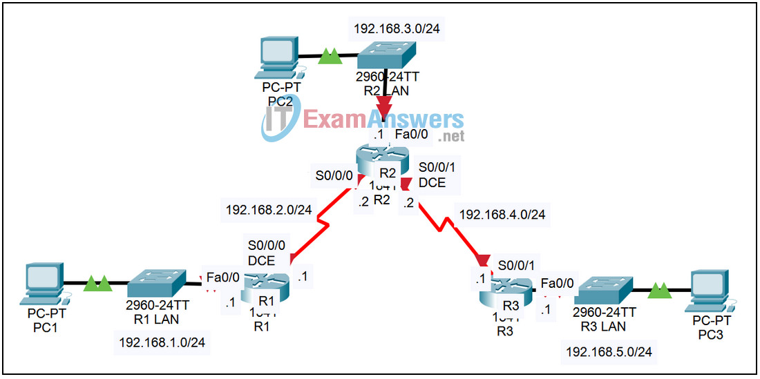
Topology

| Device | Interface | IP Address | Subnet Mask | Default Gateway |
|---|---|---|---|---|
| R1 | Fa0/0 | 192.168.1.1 | 255.255.255.0 | N/A |
| S0/0/0 | 192.168.2.1 | 255.255.255.0 | N/A | |
| R2 | Fa0/0 | 192.168.3.1 | 255.255.255.0 | N/A |
| S0/0/0 | 192.168.2.2 | 255.255.255.0 | N/A | |
| S0/0/1 | 192.168.4.2 | 255.255.255.0 | N/A | |
| R3 | Fa0/0 | 192.168.5.1 | 255.255.255.0 | N/A |
| S0/0/1 | 192.168.4.1 | 255.255.255.0 | N/A | |
| PC1 | NIC | 192.168.1.10 | 255.255.255.0 | 192.168.1.1 |
| PC2 | NIC | 192.168.3.10 | 255.255.255.0 | 192.168.3.1 |
| PC3 | NIC | 192.168.5.10 | 255.255.255.0 | 192.168.5.1 |
Introduction:
In order to reach networks that are not directly connected, additional entries are needed in the IP routing table. These entries could be configured by the network administrator or learned dynamically from other routers. RIP (Routing Information Protocol) can be configured to allow routers to exchange information and learn about remote networks.
Learning Objectives:
- Configure RIP on routers.
- Verify the configuration.
- Examine RIP parameters.
- Check connectivity.
- Examine the IP routing table.
Task 1: Configure RIP on routers.
Step 1 – Access router R1 and enter global configuration mode.
From the CLI tab, enter the privileged exec mode by issuing the enable command. Enter the global configuration mode by issuing the command config t.
Step 2 – Configure RIP.
- Enter the router configuration mode by issuing the command router rip.
- In router configuration mode, you need to specify the networks that are directly connected to the router to start the routing process for those networks. There are two networks directly connected to router R1, 192.168.1.0/24 and 192.168.2.0/24.
- Configure the first network by issuing the command network 192.168.1.0.
- Configure the second network by issuing the command network 192.168.2.0.
Step 3 – Save the configuration.
Exit the configuration mode by hitting Ctrl+z. Save the configuration by issuing the command copy run start.
Step 4 – Configure routers R2 and R3.
Repeat Steps 1 through 3 for the other two routers using the information in the table above.
Task 2: Verify the configuration.
Step 1 – Examine the RIP parameters.
On each of the three routers, examine RIP parameters by issuing the command show ip protocols.
Step 2 – Examine the IP routing table.
On each of the three routers, examine the IP routing table by issuing the command show ip route. There should be an entry in the routing table for all five networks.
Step 3 – Check connectivity.
Verify full connectivity by pinging from each PC to the other two PCs. All pings should succeed.
