6.3.3.8 Packet Tracer – Inter-VLAN Routing Challenge (Instructor Version – Optional Lab)
Instructor Note: Red font color or gray highlights indicate text that appears in the instructor copy only. Optional activities are designed to enhance understanding and/or to provide additional practice.
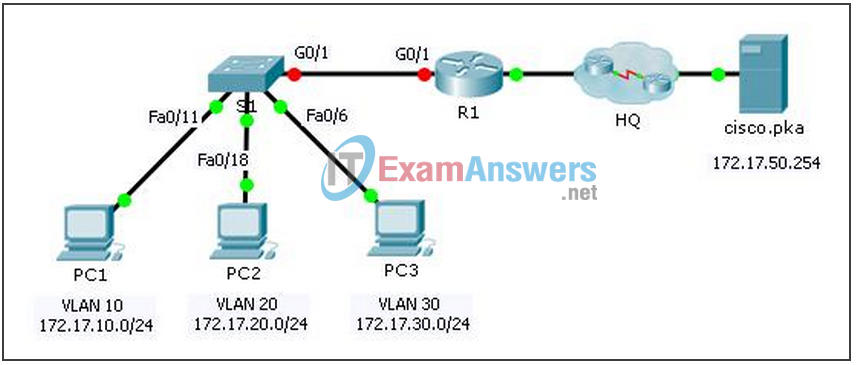
Topology

Addressing Table
| Device | Interface | IP Address | Subnet Mask | Default Gateway |
|---|---|---|---|---|
| R1 | G0/0 | 172.17.25.2 | 255.255.255.252 | N/A |
| G0/1.10 | 172.17.10.1 | 255.255.255.0 | N/A | |
| G0/1.20 | 172.17.20.1 | 255.255.255.0 | N/A | |
| G0/1.30 | 172.17.30.1 | 255.255.255.0 | N/A | |
| G0/1.88 | 172.17.88.1 | 255.255.255.0 | N/A | |
| G0/1.99 | 172.17.99.1 | 255.255.255.0 | N/A | |
| S1 | VLAN 99 | 172.17.99.10 | 255.255.255.0 | 172.17.99.1 |
| PC1 | NIC | 172.17.10.21 | 255.255.255.0 | 172.17.10.1 |
| PC2 | NIC | 172.17.20.22 | 255.255.255.0 | 172.17.20.1 |
| PC3 | NIC | 172.17.30.23 | 255.255.255.0 | 172.17.30.1 |
VLAN and Port Assignments Table
| VLAN | Name | Interface |
|---|---|---|
| 10 | Faculty/Staff | Fa0/11-17 |
| 20 | Students | Fa0/18-24 |
| 30 | Guest(Default) | Fa0/6-10 |
| 88 | Native | G0/1 |
| 99 | Management | VLAN 99 |
Scenario
In this activity, you will demonstrate and reinforce your ability to implement inter-VLAN routing, including configuring IP addresses, VLANs, trunking and subinterfaces.
Requirements
- Assign IP addressing to R1 and S1 based on the Addressing Table.
- Create, name and assign VLANs on S1 based on the VLAN and Port Assignments Table. Ports should be in access mode.
- Configure S1 to trunk, allow only the VLANs in the VLAN and Port Assignments Table.
- Configure the default gateway on
- All ports not assigned to a VLAN should be disabled.
- Configure inter-VLAN routing on R1 based on the Addressing Table.
- Verify connectivity. R1, S1, and all PCs should be able to ping each other and the cisco.pka server.
!S1!!!!!!!!!!!!!!
en
config t
interface vlan 99
ip address 172.17.99.10 255.255.255.0
no shutdown
ip default-gateway 172.17.99.1
!Note: VLAN naming only requires the first letter be correct
vlan 10
name Faculty/Staff
vlan 20
name Students
vlan 30
name Guest(Default)
vlan 88
name Native
vlan 99
name Management
interface range fa0/11 - 17
switchport mode access
switchport access vlan 10
interface range fa0/18 - 24
switchport mode access
switchport access vlan 20
interface range fa0/6 - 10
switchport mode access
switchport access vlan 30
interface g0/1
switchport mode trunk
switchport trunk native vlan 99
interface range fa0/1 - 5 , g1/2
shutdown
do write

!R1!!!!!!!!!!!!!!!!!!
ena
conf t
interface GigabitEthernet0/1
no shutdown
interface GigabitEthernet0/1.10
encapsulation dot1Q 10
ip address 172.17.10.1 255.255.255.0
interface GigabitEthernet0/1.20
encapsulation dot1Q 20
ip address 172.17.20.1 255.255.255.0
interface GigabitEthernet0/1.30
encapsulation dot1Q 30
ip address 172.17.30.1 255.255.255.0
interface GigabitEthernet0/1.88
encapsulation dot1Q 88 native
ip address 172.17.88.1 255.255.255.0
interface GigabitEthernet0/1.99
encapsulation dot1Q 99
ip address 172.17.99.1 255.255.255.0
do write
