7.1.5 Packet Tracer – Verify Non-Convergence Using Commands Answers
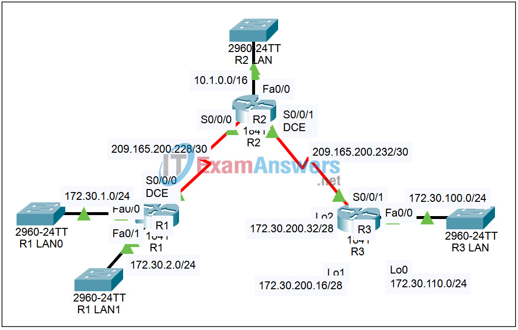
Topology

| Device | Interface | IP Address | Subnet Mask | Default Gateway |
|---|---|---|---|---|
| R1 | Fa0/0 | 172.30.1.1 | 255.255.255.0 | N/A |
| Fa0/1 | 172.30.2.1 | 255.255.255.0 | N/A | |
| S0/0/0 | 209.165.200.230 | 255.255.255.252 | N/A | |
| R2 | Fa0/0 | 10.1.0.1 | 255.255.0.0 | N/A |
| S0/0/0 | 209.165.200.229 | 255.255.255.252 | N/A | |
| S0/0/1 | 209.165.200.233 | 255.255.255.252 | N/A | |
| R3 | Fa0/0 | 172.30.100.1 | 255.255.255.0 | N/A |
| Lo0 | 172.30.110.1 | 255.255.255.0 | N/A | |
| Lo1 | 172.30.200.17 | 255.255.255.240 | N/A | |
| Lo2 | 172.30.200.33 | 255.255.255.240 | N/A | |
| S0/0/1 | 209.165.200.234 | 255.255.255.252 | N/A |
Introduction
In this activity, we will use Packet Tracer to examine some of the problems encountered when using RIPv1, in the network introduced in this section containing discontiguous subnets.
Learning Objectives:
- Verifying and testing connectivity.
- Examining the routing tables.
- Examine the routing updates sent and received on R2.
- View the problems in Simulation mode.
Task 1: Verifying and testing connectivity.
Step 1 – Ping from router R2.
Access router R2 and from the CLI issue the following commands:
- Verify link status by issuing the command show ip interface brief.
- ping 172.30.1.1 – the ping will be partially successful.
- ping 172.30.100.1 – the ping will be partially successful.
Step 2 – Ping from Router R1.
Access router R1 and from the CLI issue the following commands:
- ping 10.1.0.1 – the ping will be successful.
- ping 172.30.100.1 – the ping will fail.
Step 3 – Ping from Router R3.
Access router R3 and from the CLI issue the following commands:
- ping 10.1.0.1 – the ping will be successful.
- ping 172.30.1.1 – the ping will fail.
Task 2: Examining the routing tables.
Step 1 – Examine the Routing table on R2.
Access router R2 and from the CLI examine the IP routing table by issuing the command show ip route. Notice the two equal cost paths to network 172.30.0.0/16. Alternate packets intended for that network are sent the wrong way.
Step 2 – Examine the Routing table on R1.
Access router R1 and from the CLI examine the IP routing table by issuing the command show ip route. Notice there is no route to network 172.30.100.0/24. Pings to that network will fail.
Step 3 – Examine the routing updates sent and received on R2.
Access router R2. From the CLI enter privileged exec mode. View routing updates by issuing the command debug ip rip. Allow the command to run for a few minutes. Notice the updates received from the other routers and the updates broadcast to the other routers. Be sure to issue the command undebug all to turn off debugging.
Task 3: View the problems in Simulation mode.
Step 1 – Simulate and trace the pings.
- Enter Simulation mode. The Event List Filters is set to show only ICMP events.
- Access router R2. From the CLI issue the command ping 172.30.1.1. Minimize the R2 window.
- Click the Auto Capture / Play button. Watch the simulation. When prompted, click the View Previous Events button.
- Click the colored boxes in the Info column in the Events List for all of the events. Examine the PDU information at Layer 3 to understand what happened during the ping.
- Reset the simulation and repeat the process for the other pings described in Task 1.
Step 2 – Simulate and trace the RIP routing process.
- Reset the Simulation. Change the Event List Filters to show only RIP events.
- Click the Auto Capture / Play button. Watch the Simulation. When prompted, click the OK button.
- Click the colored boxes in the Info column in the Events List for all of the events. Examine the PDU information at Layer 3, 4, and 7 to understand the exchange process. Examine the Inbound and Outbound PDU details to understand the content of the RIP updates.
