7.1.2 Packet Tracer – Configuring Discontiguous Routes Answers
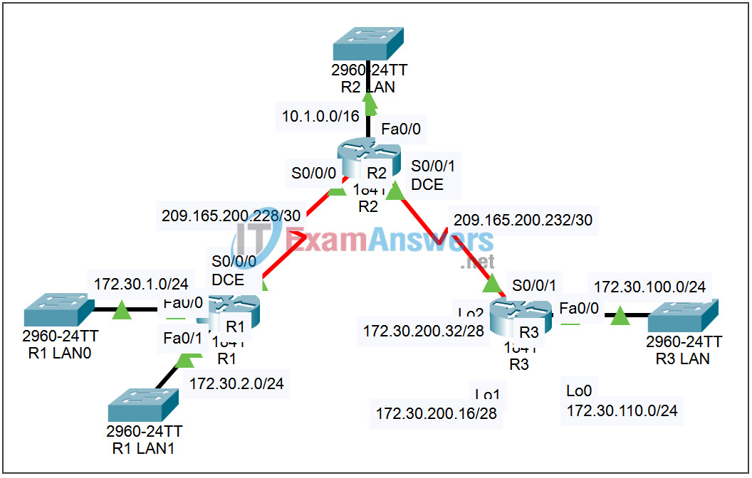
Topology

| Device | Interface | IP Address | Subnet Mask | Default Gateway |
|---|---|---|---|---|
| R1 | Fa0/0 | 172.30.1.1 | 255.255.255.0 | N/A |
| Fa0/1 | 172.30.2.1 | 255.255.255.0 | N/A | |
| S0/0/0 | 209.165.200.230 | 255.255.255.252 | N/A | |
| R2 | Fa0/0 | 10.1.0.1 | 255.255.0.0 | N/A |
| S0/0/0 | 209.165.200.229 | 255.255.255.252 | N/A | |
| S0/0/1 | 209.165.200.233 | 255.255.255.252 | N/A | |
| R3 | Fa0/0 | 172.30.100.1 | 255.255.255.0 | N/A |
| Lo0 | 172.30.110.1 | 255.255.255.0 | N/A | |
| Lo1 | 172.30.200.17 | 255.255.255.240 | N/A | |
| Lo2 | 172.30.200.33 | 255.255.255.240 | N/A | |
| S0/0/1 | 209.165.200.234 | 255.255.255.252 | N/A |
Introduction
In this activity we will review the basic configuration of RIP, Routing Information Protocol. We will configure RIP on the network introduced in this section containing discontiguous subnets. Since Packet Tracer does not support redistribution of static routes or null interfaces these configurations will not be included.
Learning Objectives:
- Configure RIP on routers.
- Verify the configuration.
- Examine RIP parameters.
- Examine the IP routing table.
- Check your configuration.
Task 1: Configure RIP on routers.
Step 1 – Access router R1 and enter global configuration mode.
From the CLI tab enter the privileged exec mode by issuing the enable command. Enter the global configuration mode by issuing the command config t.
Step 2 – Configure RIP.
Enter the router configuration mode by issuing the command router rip.
In router configuration mode, you need to specify the directly connected networks to start the routing process for those networks. There are three networks directly connected to router R1, 172.30.1.0/24, 172.30.2.0/24 and 209.165.200.228/30.
Because RIP accepts only classful networks in its network statements, we can combine the first two networks in a single statement. Configure the first two networks by issuing the command network 172.30.0.0.
The third network is a subnet of a class C network. Configure the third network by issuing the command network 209.165.200.0.
There are no routers on either FastEthernet interface. Suppress sending updates out those interfaces by issuing the commands passive-interface fa0/0 and passive-interface fa0/1.
Step 3 – Save the configuration.
Exit the configuration mode by using Ctrl+z. Save the configuration by issuing the command copy run start.
Step 4 – Configure routers R2 and R3.
Repeat Steps 1 through 3 for the other two routers using the information in the table above.
Task 2: Verify the configuration.
Step 1 – Examine RIP parameters.
On each of the three routers, examine RIP parameters by issuing the command show ip protocols.
Step 2 – Examine the IP routing table.
On each of the three routers, examine the IP routing table by issuing the command show ip route.
