7.5.2 Packet Tracer – Challenge Wireless WRT300N Answers
Topology
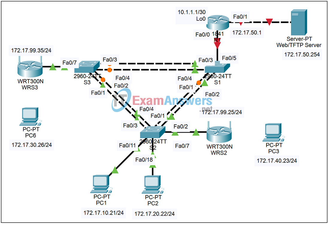
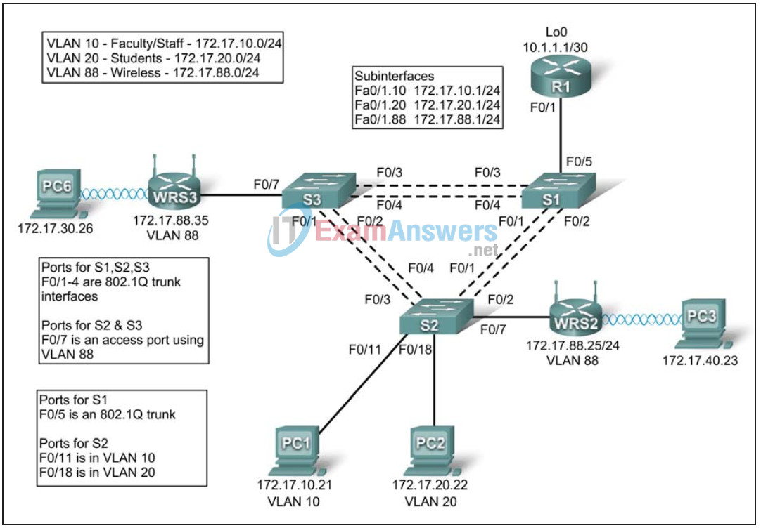
Addressing Table
| Device | Interface | IP Address | Subnet Mask | Default Gateway |
|---|---|---|---|---|
| R1 | Fa0/1.10 | 172.17.10.1 | 255.255.255.0 | N/A |
| Fa0/1.20 | 172.17.20.1 | 255.255.255.0 | N/A | |
| Fa0/1.88 | 172.17.88.1 | 255.255.255.0 | N/A | |
| Lo0 | 10.1.1.1 | 255.255.255.252 | N/A | |
| WRS2 | WAN | 172.17.88.25 | 255.255.255.0 | 172.17.88.1 |
| LAN/Wireless | 172.17.40.1 | 255.255.255.0 | N/A | |
| WRS3 | WAN | 172.17.88.35 | 255.255.255.0 | 172.17.88.1 |
| LAN/Wireless | 172.17.30.1 | 255.255.255.0 | N/A | |
| PC1 | NIC | 172.17.10.21 | 255.255.255.0 | 172.17.10.1 |
| PC2 | NIC | 172.17.20.22 | 255.255.255.0 | 172.17.20.1 |
Learning Objectives
Upon completion of this lab, you will be able to:
- Configure switch port VLAN information and port security
- Hard reset a Linksys WRT300N router
- Connect and verify connectivity to a wireless router
- Navigate to a Linksys WRT300N’s web utility page
- Configure the IP settings of a Linksys WRT300N
- Configure DHCP on a Linksys WRT300N
- Configure static routes on both standard Cisco routers and on a WRT300N
- Change the network mode and corresponding network channel on a WRT300N
- Learn how to enable WEP encryption and disable SSID broadcast
- Enable a wireless MAC filter
- Configure access restrictions on a WRT300N
- Configure router management password on a WRT300N
- Enable logging on a WRT300N
- Upgrade WRT300N firmware
- Learn diagnosis, backup, restore, and confirmation mechanisms on a WRT300N
Scenario
In this lab, you will configure a Linksys WRT300N, port security on a Cisco switch, and static routes on multiple devices. Make note of the procedures involved in connecting to a wireless network because some changes involve disconnecting clients, which may then have to reconnect after making changes to the configuration.
Task 1: Perform Basic Router Configurations
Configure R1 according to the following guidelines:
- Router hostname
- Disable DNS lookup
- EXEC mode password
- Fast Ethernet 0/1 and Fast Ethernet 0/0 and its subinterfaces
- Loopback0
- Synchronous logging, exec-timeout, and a login of cisco on the console port
enable
configure terminal
no ip domain-lookup
enable secret cisco
interface FastEthernet0/1.1
 encapsulation dot1 1
 ip address 172.17.1.1 255.255.255.0
!
interface FastEthernet0/1.10
 encapsulation dot1 10
 ip address 172.17.10.1 255.255.255.0
!
interface FastEthernet0/1.20
 encapsulation dot1 20
 ip address 172.17.20.1 255.255.255.0
!
interface FastEthernet0/1.88
 encapsulation dot1 88
 ip address 172.17.88.1 255.255.255.0
!
interface Loopback 0
 ip address 10.1.1.1 255.255.255.252
!
line con 0
 exec-timeout 0 0
 logging synchronous
 password cisco
 login
!
Task 2: Configure Switch Interfaces
Set the switches to transparent, clear the VLAN information, and create VLANs 10, 20, and 88.
<For all three switches>
 !
vtp mode transparent
no vlan 2-1001
vlan 10,20,88
!
Step 1: Configure switch port interfaces on S1, S2, and S3.
Configure the interfaces on the S1, S2, and S3 switches with the connections from topology diagram.
On connections between two switches configure trunks.
On connections to a wireless router configure them as access mode for vlan 88.
Configure S2’s connection to PC1 in vlan 10 and PC2’s connection in vlan 20.
Configure S1’s connection to R1 as a trunk.
Allow all VLANS across trunking interfaces.
S1
!
interface FastEthernet 0/1
 switchport trunk encapsulation dot1q
 switchport mode trunk
 no shutdown
!
interface FastEthernet 0/2
 switchport trunk encapsulation dot1q
 switchport mode trunk
 no shutdown
!
interface FastEthernet 0/3
 switchport trunk encapsulation dot1q
 switchport mode trunk
 no shutdown
!
interface FastEthernet 0/4
 switchport trunk encapsulation dot1q
 switchport mode trunk
 no shutdown
!
interface FastEthernet0/5
 switchport trunk encapsulation dot1q
 switchport mode trunk
 no shutdown
!
S2
!
interface FastEthernet 0/1
 switchport trunk encapsulation dot1q
 switchport mode trunk
 no shutdown
!
interface FastEthernet 0/2
 switchport trunk encapsulation dot1q
 switchport mode trunk
 no shutdown
!
interface FastEthernet 0/3
 switchport trunk encapsulation dot1q
 switchport mode trunk
 no shutdown
!
interface FastEthernet 0/4
 switchport trunk encapsulation dot1q
 switchport mode trunk
 no shutdown
!
interface FastEthernet0/7
 switchport mode access
 switchport access vlan 88
 no shutdown
!
S3
!
interface FastEthernet 0/1
 switchport trunk encapsulation dot1q
 switchport mode trunk
 no shutdown
!
interface FastEthernet 0/2
 switchport trunk encapsulation dot1q
 switchport mode trunk
 no shutdown
!
interface FastEthernet 0/3
 switchport trunk encapsulation dot1q
 switchport mode trunk
 no shutdown
!
interface FastEthernet 0/4
 switchport trunk encapsulation dot1q
 switchport mode trunk
 no shutdwn
!
interface FastEthernet 0/7
 switchport mode access
 switchport access vlan 88
 no shutdown
!
interface FastEthernet 0/11
 switchport mode access
 switchport access vlan 11
 no shutdown
!
interface FastEthernet 0/18
 switchport mode access
 switchport access vlan 20
 no shutdown
!
Step 2: Verify VLANs and trunking.
Use the show ip interface trunk command on S1 and the show vlan command on S2 to verify that the switches are trunking correctly and the proper VLANs exist.
S1#show interface trunk

Port        Mode           Encapsulation  Status        Native vlan
Fa0/1       on             802.1q         trunking      1
Fa0/2       on             802.1q         trunking      1
Fa0/3       on             802.1q         trunking      1
Fa0/4       on             802.1q         trunking      1
Fa0/5       on             802.1q         trunking      1

Port      Vlans allowed on trunk
Fa0/1       1-4094
Fa0/2       1-4094
Fa0/3      1-4094
Fa0/4      1-4094
Fa0/5      1-4094

Port       Vlans allowed and active in management domain
Fa0/1      1,10,20,88
Fa0/2      1,10,20,88
Fa0/3      1,10,20,88
Fa0/4      1,10,20,88
Fa0/5      1,10,20,88

Port       Vlans in spanning tree forwarding state and not pruned

Port       Vlans in spanning tree forwarding state and not pruned
Fa0/1      1,10,20,88
Fa0/2      none         <-- blocked due to spanning tree
Fa0/3      1,10,20,88
Fa0/4      1,10,20,88
Fa0/5      1,10,20,88>

S2#show vlan
VLAN Name                             Status    Ports
---- -------------------------------- --------- -----------------------------
1    default                          active    Fa0/5, Fa0/6, Fa0/8, Fa0/9
                                                Fa0/10, Fa0/12, Fa0/13,Fa0/14
                                                Fa0/15, Fa0/16, Fa0/17,Fa0/19
                                                Fa0/20, Fa0/21, Fa0/22,Fa0/23
                                                Fa0/24, Gi0/1, Gi0/2
10   VLAN0010                         active    Fa0/11
20   VLAN0020                         active    Fa0/18
88   VLAN0088                         active    Fa0/7
1002 fddi-default                     act/unsup
1003 token-ring-default               act/unsup
1004 fddinet-default                  act/unsup
1005 trnet-default                    act/unsup
When you have finished, be sure to save the running configuration to the NVRAM of the router and switches.
Step 3: Configure the Ethernet interfaces of PC1 and PC2.
Configure the Ethernet interfaces of PC1 and PC2 with the IP addresses and default gateways according to the addressing table at the beginning of the lab.
Step 4: Test the PC configuration.
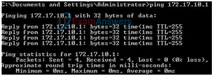
Ping the default gateway from the PC: 172.17.10.1 for PC1, and 172.17.20.1 from PC2.
Go to Start->Run->cmd and type ping 172.17.x.x
Task 3: Connect to the Linksys WRT300N Router
Check with your instructor that the wireless router has its factory default settings. If it does not, you must hard reset the router. To do so, find the reset button on the back of the router. Using a pen or other thin instrument, hold down the reset button for 5 seconds. The router should now be restored to its factory default settings.
Step 1: Use Windows XP to connect to the wireless router.
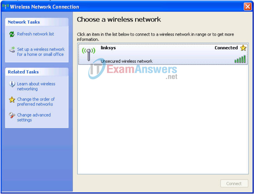
Locate the Wireless Network Connection icon in your taskbar, or go to Start > Control Panel > Network Connections. Right-click the icon and select View Available Wireless Networks.
You are prompted with the following display. Note that the factory default SSID of the router is simply “Linksys.”
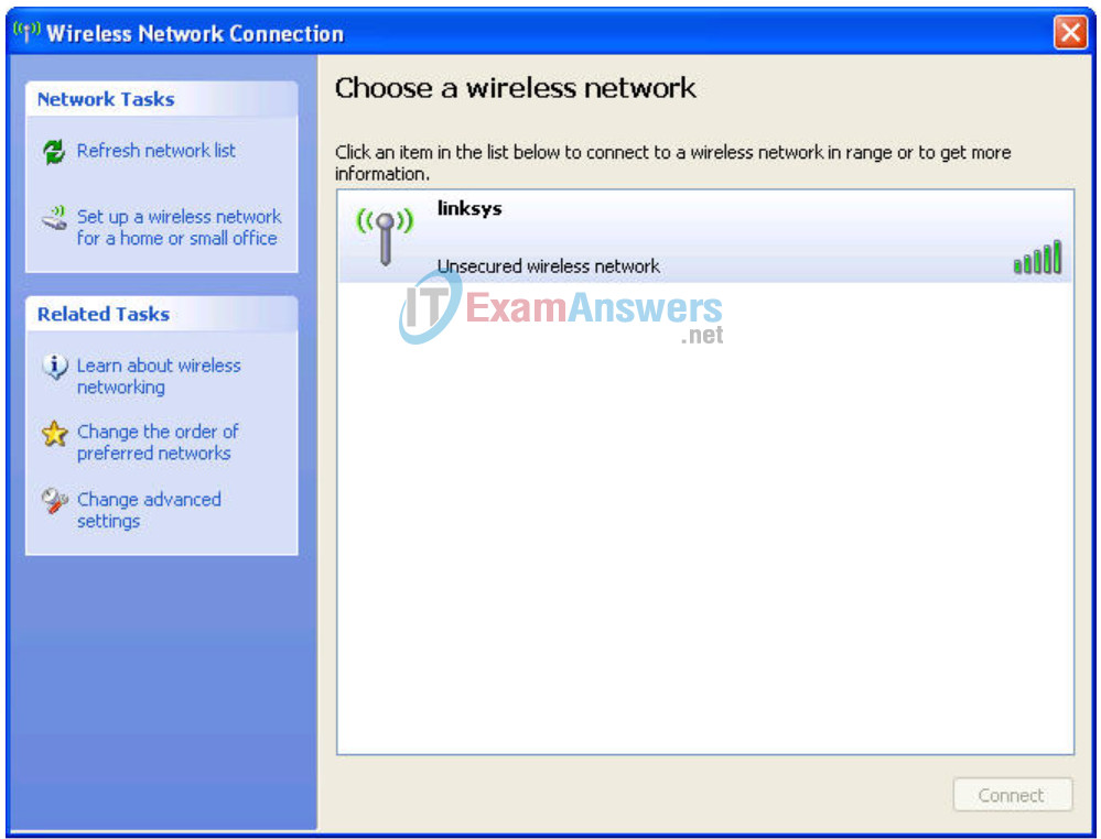
Select Linksys and click Connect.

After a period of time you will be connected.
Step 2: Verify connectivity settings.
Verify the connectivity settings by going to Start > Run and typing cmd. At the command prompt, type the command ipconfig to view your network device information. Notice which IP address is the default gateway. This is the default IP address of a Linksys WRT300N.

Task 4: Configure the WRT300N Using the Web Utility
Step 1: Go to the default URL.
In your favorite web browse, navigate to http://192.168.1.1 which is the default URL for the WRT300N.

Step 2: Enter authentication information.
You are prompted for a username and password. Enter the WRT300N factory default password of admin and leave the username field blank.
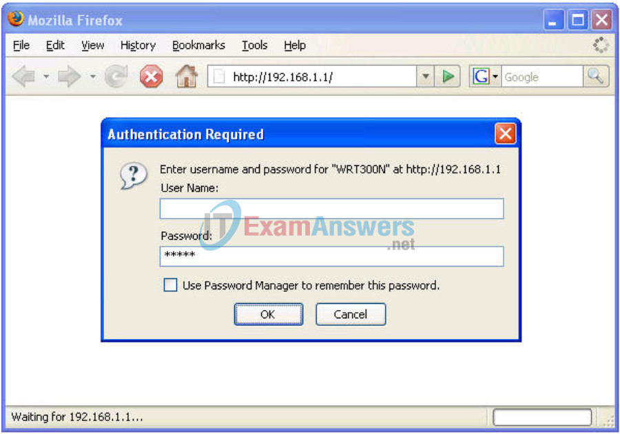
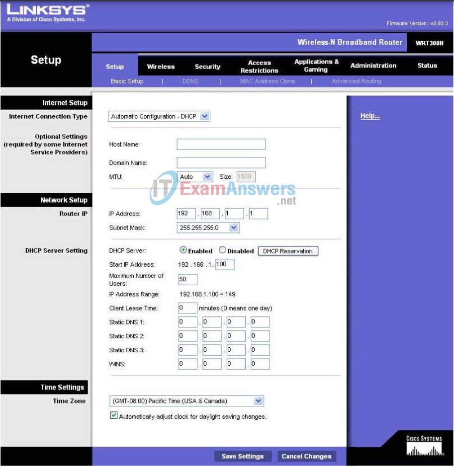
You should now be viewing the default page of the Linksys WRT300N web utility.
Task 5: Configure IP Settings for the Linksys WRT300N
The best way to understand the following settings is to think of the WRT300N as being similar to a Cisco IOS-based router with two separate interfaces. One of the interfaces, the one configured under Internet Setup, acts as the connection to the switches and the interior of the network. The other interface, configured under Network Setup, acts as the interface connecting to the wireless clients, PC6 and PC3.
Step 1: Set the Internet connection type to static IP.
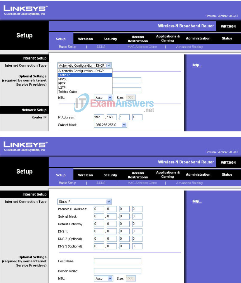
Step 2: Set the IP address settings for Internet Setup.
- Set the Internet IP address to 172.17.88.35.
- Set the subnet mask to 255.255.255.0.
- Set the default gateway to the Fa 0/1 VLAN 88 IP address of R1, 172.17.88.1.
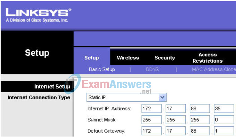
Step 3: Configure the Network Setup IP address to 172.17.30.1.

Step 4: Save the settings.
Click Save Settings. You are prompted with the following window. Click Continue. If you are not redirected to the new URL of the web utility (http://172.17.30.1), navigate your browser there as you did in Task 4, Step 1.

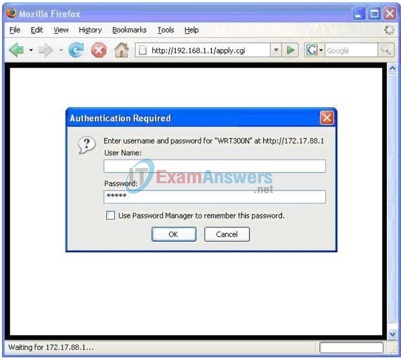
Step 5: Verify IP address changes.
Go back to the command prompt and notice the new IP addresses. Use the command ipconfig.

Task 6: Configure DHCP Settings and Router Time Zone Settings
Step 1: Give Pc6 a static DHCP binding.
Click DHCP Reservations and find Pc6 in the list of current DHCP clients. Click Add Clients.

This gives Pc6, the computer with a MAC address of 00:05:4E:49:64:F8, the same IP address, 172.17.30.100, whenever it requests an address through DHCP. This is only an example of a quick way to permanently bind a client to its current DHCP-given IP address. Now, you will assign Pc6 the IP address in the topology diagram, not the one it received initially. Click Remove to assign a new address.

Step 2: Assign Pc6 the 172.17.30.26 address.
By entering the Pc6 address under Manually Adding Client, whenever Pc6 connects to the wireless router, it receives the IP address 172.17.30.26 via DHCP. Save your changes.

Step 3: Verify the static IP address change.
Since we already have an IP address from DHCP we are not going to get the new address, 172.17.30.26, until we reconnect. We will wait and notice that later in Task 6, Step 5 and verify that this change has taken place.
Step 4: Configure the DHCP server.
Set the start address to 50, the maximum number of users to 25, and the lease time to 2 hours (or 120 minutes).

These settings give any PC that connects to this router wirelessly requesting an IP address through DHCP, an address between 172.17.30.50–74. Only 25 clients at a time are able to get an IP address and can only have the IP address for two hours, after which time they must request a new one.
Note: IP Address Range does not update until you click Save Settings.
Step 5: Configure the router for the appropriate time zone.
At the bottom of the Basic Setup page, change the time zone of the router to reflect your location.

Step 6: Save your settings!
Task 7: Basic Wireless Settings
Step 1: Set the network mode.
The Linksys WRT300N allows you to choose in which network mode to operate. Currently, the most used network mode for clients is Wireless-G and for routers is BG-Mixed. When a router is operating in BG-Mixed, it can accept both B and G clients. However, if a B client connects, the router must scale down to the slower level of B. For this lab, we are assuming all clients are running B only, so choose Wireless-B Only.
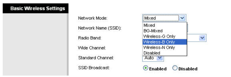
Step 2: Configure other settings.
Change the Network Name SSID to WRS3, Standard Channel to 6 – 2.437GHZ, and disable SSID Broadcast.
Why is it good to change the wireless channel to be different from the default channel?
To help prevent interference from other wireless routers
Why is it recommended to disable SSID broadcast?
This allows a measure of security. Someone attempting to connect to the router minimally needs to know the SSID before being able to connect to it.
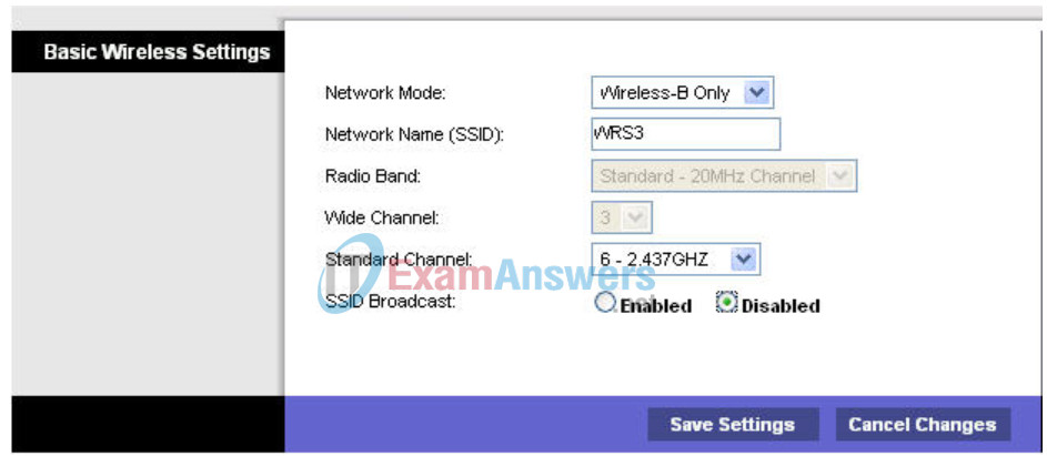
Step 3: Click Save Settings.
Step 4: Verify that the SSID of the router is no longer being broadcast.
Scan for wireless networks, as done in Task 3, Step 1. Does the SSID of the wireless router appear?
No
Step 5: Reconnect to the wireless network.
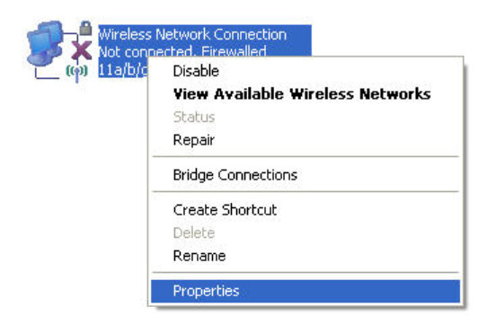
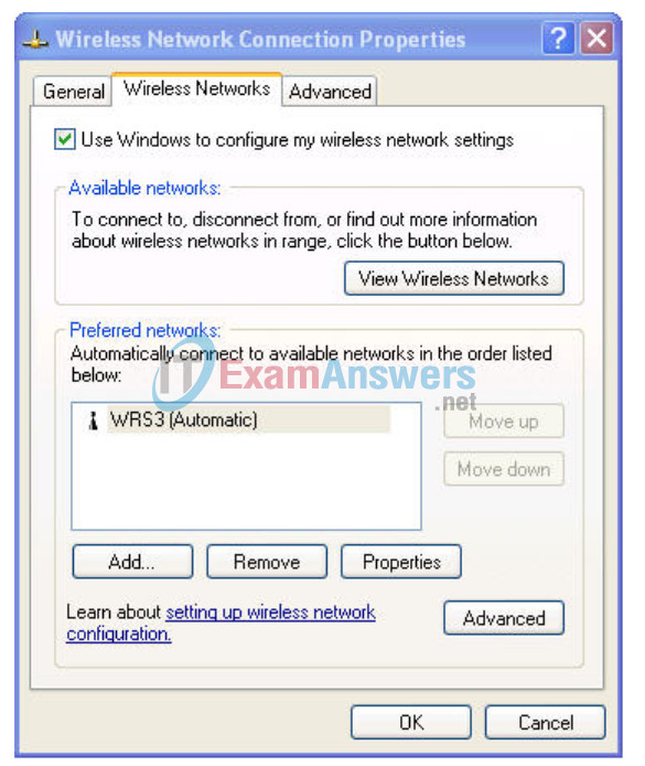
Navigate to Start > Control Panel > Network Connections, right-click the Wireless Network Connection icon, and select Properties.
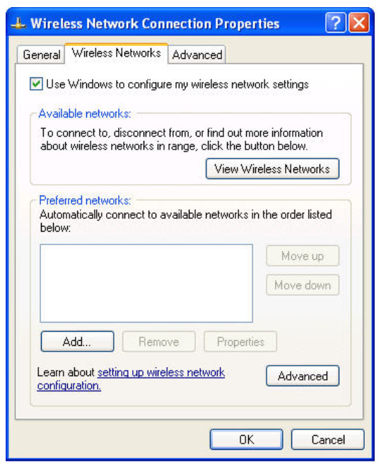
In the Wireless Networks tab, select Add.
In the Association Tab, enter WR33 as the SSID, and set the Data Encryption to Disabled. Select OK, and then select OK again. Windows should now try to reconnect to the wireless router.
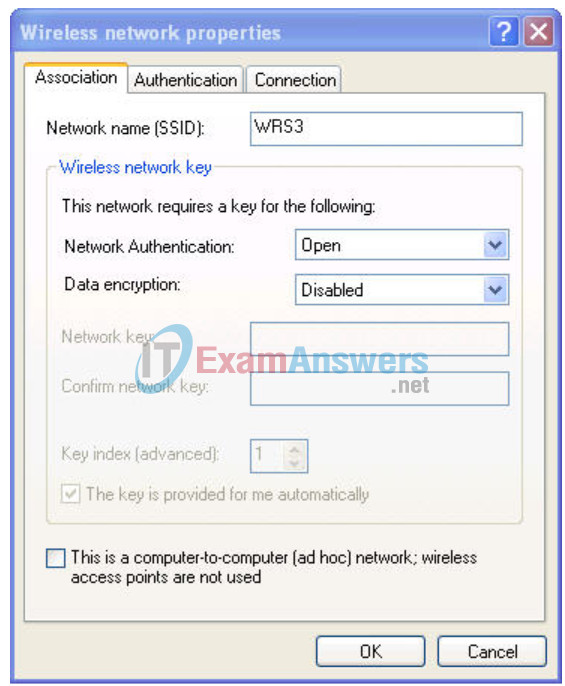
Step 6: Verify the settings.
Now that you have reconnected to the network, you have the new DHCP settings that you configured in Task 5, Step 3. Verify this at the command prompt with the ipconfig command.

Task 8: Enable Wireless Security
Step 1: Reconnect to the router setup page (http://172.17.30.1).
Step 2: Navigate to the Wireless page and then select the Wireless Security tab.
Step 3: Under Security Mode, select WEP.

Step 4: Enter a WEP key.
A network is only as secure as its weakest point, and a wireless router is a very convenient place to start if someone wants to damage your network. By not broadcasting the SSID and requiring a WEP key to connect to the router, you are adding a few levels of security.
Unfortunately, there are tools that can discover networks that are not even broadcasting their SSID, and there are even tools that can crack WEP key encryption. A more robust form of wireless security is WPA and WPA-2, which are currently not supported on this router. Wireless MAC filters is more secure but sometimes impractical means of securing your network. It is discussed in the next task.
Add the WEP key 1234567890.
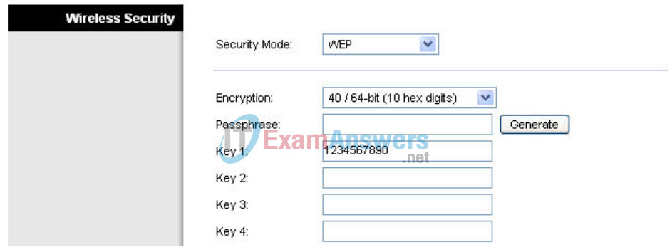
Step 5: Save your settings.
You will become disconnected from the network.
Step 6: Configure Windows to use WEP authentication.
Navigate to the Network Connections page again and right-click the Wireless Network Connection icon. In the Wireless Networks tab, locate the WRS3 network, and click Properties.
- Set Data Encryption to WEP.
- Uncheck This Key Is Provided For Me.
- Enter the network key of 1234567890, as configured before on the router.
- Click OK and OK.
Windows should now reconnect to the network.
Task 9: Configure a Wireless MAC Filter
Step 1: Add a Mac filter.
- Navigate back to the web utility page of the router (http://172.17.30.1).
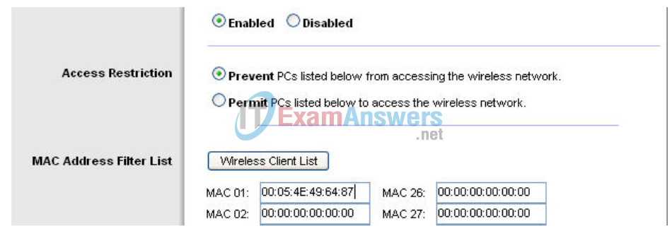
- Navigate to the Wireless section and then to the Wireless MAC Filter tab.
- Check Enabled.
- Select Prevent PCs listed below from accessing the wireless network.
- Enter the MAC address 00:05:4E:49:64:87.
This prevents any client with the MAC address 00:05:4E:49:64:87 from accessing the wireless network.
Step 2: Click Wireless Client List.
The Wireless Client List shows anyone currently connected to the router via a wireless connection. Also take note of the option Save to MAC filter list. Checking this option automatically adds the MAC address of that client to the list of MAC addresses to prevent or permit access to the wireless network.
What is an extremely robust way of only allowing clients of your choosing to connect to the wireless network?
You could set the Access Restriction to Permit, which only allows MAC addresses listed in the table to connect wirelessly.
Why does this become not feasible in large networks?
You have to manually enter each MAC address.
What is a convenient way of adding MAC addresses if everyone to whom you wanted to allow access was already connected to the wireless network?
You could simply go to the Wireless Client List and check Save to MAC filter list.
Task 10: Setting Access Restrictions
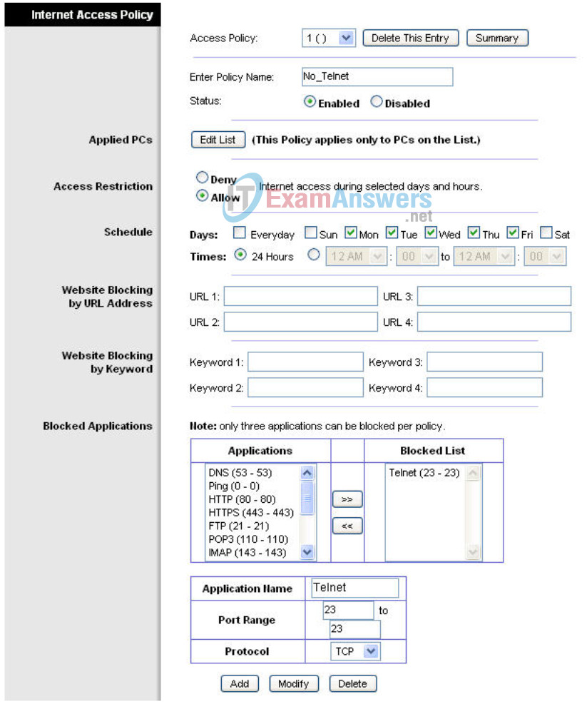
Configure an access restriction that prevents Telnet access Monday through Friday to users getting a DHCP address from the preset pool (172.17.30.50 – 74).
Step 1: Navigate to the Access Restrictions tab.
In the Access Restrictions tab, set the following:
- Policy Name – No_Telnet
- Status – Enabled
- Internet access – Allow
- Days – Check Monday through Friday
- Blocked List – Add Telnet
Step 2: Set the IP address range.
Apply this configuration to anyone that is using a default DHCP address in the range of 172.17.30.50 – 74.
Click the Edit List button at the top of the window and enter the IP address range. Save the settings.

Save the access restriction settings
Task 11: Managing and Securing the Web Utility of the Router
Step 1: Configure web access.
Navigate to the Administration section. Change the router password to cisco.
For Web Utility Access, select both HTTP and HTTPS. Selecting HTTPS access allows a network administrator to manage the router via https://172.17.30.1 with SSL, a more secure form of HTTP. If you choose to do this in the lab, you may have to accept certificates.

For Web Utility Access via Wireless, select Enabled. If you disabled this option, the Web Utility would not be available to clients connected wirelessly. Disabling access is another form of security, because it requires the user to be directly connected to the router before changing settings. However, in this lab scenario, you are configuring the router via wireless access, so disabling access would not be a good idea!
Now back up your configuration by clicking the Backup Configurations button. When prompted, save the file to your desktop.

Step 2: Restore your configuration.
If your settings are accidentally or intentionally changed or erased, you can restore them from a working configuration using the Restore Configurations option located in the Backup and Restore section.
Click the Restore Configuration button now. In the Restore Configurations window, browse to the previously saved configuration file. Click the Start to Restore button. Your previous settings should be successfully restored.

Step 3: Enable logging.
Navigate to the Log tab and enable logging. You are now able to view the log of the router.

Step 4: Save your settings and end your wireless connection to the router.
Step 5: Plug an Ethernet cable into one of the wireless router’s LAN ports and connect to it
Step 6: Navigate to the router’s Web GUI.
Step 7: Navigate to the Administration section
Step 8: Upgrade the firmware.
Go to
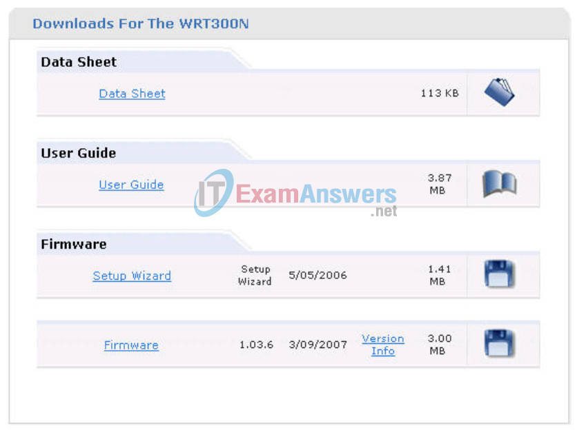
http://www.linksys.com/servlet/Satellite?c=L_CASupport_C2&childpagename=US%2FLayout&cid=1166859841746&pagename=Linksys%2FCommon%2FVisitorWrapper&lid=4174637314B274&displaypage=download
Select your router version. Instructions for identifying the version are located on the Linksys website.
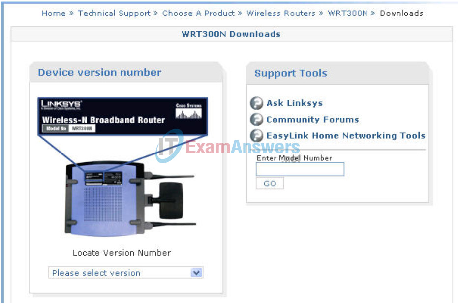
Either click Firmware or the save icon. If prompted, save the file to the disk.
Before upgrading, notice the current firmware version in the upper right corner.
Navigate to the Administration section. Click Upgrade Firmware. Browse to the file you just downloaded. Click Start to Upgrade. The upgrade should not be interrupted, so make sure to not power off the device.
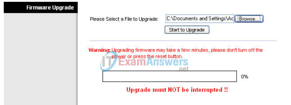

When completed, check the new version of firmware on your device.
Task 12: Creating and Verifying Full Connectivity
Step 1: Filter anonymous Internet requests.
In the Security section, uncheck Filter Anonymous Internet Requests. Disabling this option allows you to ping the WRS3 internal LAN/wireless IP address, 172.17.30.1, from places connected to its WAN port.

Step 2: Disable NAT.
In the Setup section, click the Advanced Routing tab. Disable NAT.

Step 3: Connect to WRS2.
Set the IP address settings for Internet Setup.
- Set the Internet IP address to 172.17.88.25.
- Set the subnet mask to 255.255.255.0.
Set the default gateway to the Fa 0/1 VLAN 88 IP address of R1, 172.17.88.1
Configure the Network Setup IP address to 172.17.30.1
Statically bind the MAC address of PC3 to the DHCP address 172.17.40.23 (hint: Task 6, Step 2).
Change the wireless SSID to WRS2 (hint: Task 7, Step 2).
Step 4: Give R1 static routes to the 172.17.30.0 and 172.17.40.0 networks.
R1config)#ip route 172.17.30.0 255.255.255.0 172.17.88.35
R1(config)#ip route 172.17.40.0 255.255.255.0 172.17.88.25
Step 5: Repeat steps 1 and 2 above for WRS2.
Step 6: Verify connectivity.
Verify that R1 has routes to PC3 and PC6 and that it can successfully ping them.
R1#sh ip route
<output deleted>

Gateway of last resort is not set

    172.17.0.0/24 is subnetted, 5 subnets
S      172.17.40.0 [1/0] via 172.17.88.25
S      172.17.30.0 [1/0] via 172.17.88.35
C      172.17.20.0 is directly connected, FastEthernet0/1.20
C      172.17.10.0 is directly connected, FastEthernet0/1.10
C      172.17.88.0 is directly connected, FastEthernet0/1.88
    10.0.0.0/24 is subnetted, 1 subnets
C      10.1.1.0 is directly connected, Loopback0

R1#ping 172.17.30.26

Type escape sequence to abort.
Sending 5, 100-byte ICMP Echos to 172.17.30.26, timeout is 2 seconds:
!!!!!
Success rate is 100 percent (5/5), round-trip min/avg/max = 1/1/4 ms

R1#ping 172.17.40.23

Type escape sequence to abort.
Sending 5, 100-byte ICMP Echos to 172.17.40.23, timeout is 2 seconds:
!!!!!
Success rate is 100 percent (5/5), round-trip min/avg/max = 1/2/4 ms
Verify that PC3 and PC6 can ping the loopback of R1.
Verify that PC3 and PC6 can ping each other.
Verify that PC3 and PC6 can ping PC1 and PC2.
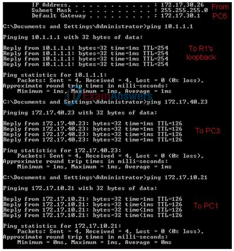
Task 13: Configuring Routing Efficiency
Step 1: Use Traceroute to view the network connection.
Because R1 is the default gateway, the Linksys router goes to R1 to get to a network it does not know how to get to, including the clients of the other Linksys routers.
A packet from PC3 to PC6 first reaches its default gateway of 172.17.40.1, then it is sent out the WRS2 WAN interface of 172.17.88.25 toward the WRS2 default gateway (172.17.88.1). From there, R1 send the packet to the WRS3 WAN interface, 172.17.88.35, where WRS3 handles it.
You can verify this in the Diagnostics tab in the Administration section. In the Traceroute Test field, enter the IP address of PC6 to PC6, 172.17.30.26

Now click Start to Traceroute, a pop-up will appear.

If WRS2 knew that it could get to the 172.17.30.0 network from 172.17.88.35 it would just directly send it to that IP address. So lets tell it!
Step 2: Configure a new route.
In the Setup section, click the Advanced Routing tab. For Static Routing, enter the following settings:
- In the Route Name field, enter To WRS2 Clients.
- For Destination LAN IP, enter the network behind WRS2: 172.17.40.0
- Enter a subnet mask of /24
- Enter a gateway of 172.17.88.35
- Set the interface to Internet (WAN)
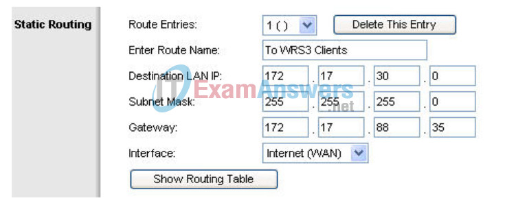
Step 3: Verify the new route.
In the Diagnostics tab in the Administration section, re-enter the IP address of PC3 in the Traceroute Test field. Click Start to Traceroute to see the route.

Notice WRS2 goes straight to WRS3 and saves us the extra hop to R1!
Do the same thing on WRS3 for the 172.17.40.0/24 network, pointing towards WRS2’s WAN interface, 172.17.88.25.

Task 14: Configuring Port Security
Step 1: Configure PC1 port security.
Log on to switch S2. Configure the PC1 switch port 11, enable port security, and enable dynamic sticky MAC addresses.
Step 2: Configure PC2 port security.
Repeat Step 1 for switch port 18.
S2
!
interface FastEthernet 0/11
 switchport mode access
 switchport access vlan 10
 switchport port-security
 switchport port-security mac-address sticky
 no shutdown
!
!
interface FastEthernet 0/18
 switchport mode access
 switchport access vlan 20
 switchport port-security
 switchport port-security mac-address sticky
 no shutdown
!
Step 3: Generate traffic across the ports by pinging PC2 from PC1.
Step 4: Verify port security.
S1#show port-security address
          Secure Mac Address Table
------------------------------------------------------------------------
Vlan    Mac Address       Type               Ports         Remaining Age
                                                              (mins)
----    -----------       ----               -----         -------------
  10    0006.5b1e.33fa    SecureSticky       Fa0/11              -
  20    0001.4ac2.22ca    SecureSticky       Fa0/18              -
------------------------------------------------------------------------
Total Addresses in System (excluding one mac per port) : 0
Max Addresses limit in System (excluding one mac per port) : 6272

S1#sh port-security int fa 0/11
Port Security              : Enabled
Port Status                : Secure-up
Violation Mode             : Shutdown
Aging Time                 : 0 mins
Aging Type                 : Absolute
SecureStatic Address Aging : Disabled
Maximum MAC Addresses      : 1
Total MAC Addresses        : 1
Configured MAC Addresses   : 0
Sticky MAC Addresses       : 1
Last Source Address:Vlan   : 0006.5b1e.33fa:10
Security Violation Count   : 0
Appendix
Configurations
Hostname R1
!
enable secret class
!
no ip domain lookup
!
interface Loopback0
 ip address 10.1.1.1 255.255.255.0
!
interface FastEthernet0/1
 no shutdown
!
interface FastEthernet0/1.10
 encapsulation dot1Q 10
 ip address 172.17.10.1 255.255.255.0
!
interface FastEthernet0/1.20
 encapsulation dot1Q 20
 ip address 172.17.20.1 255.255.255.0
!
interface FastEthernet0/1.88
 encapsulation dot1Q 88
 ip address 172.17.88.1 255.255.255.0
!
!
ip route 172.17.30.0 255.255.255.0 172.17.88.35
ip route 172.17.40.0 255.255.255.0 172.17.88.25
!
!
!
!
line con 0
 exec-timeout 0 0
 logging synchronous
 password cisco
line aux 0
line vty 0 4
!
!
end
Hostname S1
!
!
vtp mode transparent
!
!
vlan 10,20,88
!
!
interface FastEthernet0/1
 switchport trunk encapsulation dot1q
 switchport mode trunk
!
interface FastEthernet0/2
 switchport trunk encapsulation dot1q
 switchport mode trunk
!
interface FastEthernet0/3
 switchport trunk encapsulation dot1q
switchport mode trunk
!
interface FastEthernet0/4
 switchport trunk encapsulation dot1q
 switchport mode trunk
!
interface FastEthernet0/5
 switchport trunk encapsulation dot1q
 switchport mode trunk
!
line con 0
 exec-timeout 0 0
 logging synchronous
!
end
Hostname S2
!
!
vtp mode transparent
!
vlan 10,20,88
!
!
interface FastEthernet0/1
 switchport trunk encapsulation dot1q
 switchport mode trunk
!
interface FastEthernet0/2
 switchport trunk encapsulation dot1q
 switchport mode trunk
!
interface FastEthernet0/3
 switchport trunk encapsulation dot1q
 switchport mode trunk
!
interface FastEthernet0/4
 switchport trunk encapsulation dot1q
 switchport mode trunk
!
interface FastEthernet0/7
 switchport mode access
 switchport access vlan 88
!
!
! PC1 and PC2’s MAC address will appear after ‘sticky’ on ports 11
! and 18 respectively, after traffic traverses them
!
!
interface FastEthernet0/11
 switchport access vlan 10
 switchport mode access
 switchport port-security
 switchport port-security mac-address sticky
 switchport port-security mac-address sticky ffff.ffff.ffff
!
interface FastEthernet0/18
 switchport access vlan 20
 switchport mode access
 switchport port-security
 switchport port-security mac-address sticky
 switchport port-security mac-address sticky ffff.ffff.ffff
!
line con 0
 exec-timeout 0 0
 logging synchronous
!
end
Hostname S3
!
vtp mode transparent
!
vlan 10,20,88
!
interface FastEthernet0/1
 switchport trunk encapsulation dot1q
 switchport mode trunk
!
interface FastEthernet0/2
 switchport trunk encapsulation dot1q
 switchport mode trunk
!
interface FastEthernet0/3
 switchport trunk encapsulation dot1q
 switchport mode trunk
!
interface FastEthernet0/4
 switchport trunk encapsulation dot1q
 switchport mode trunk
!
interface FastEthernet0/7
 switchport mode access
 switchport access vlan 88
!
!
line con 0
 exec-timeout 0 0
 logging synchronous
!
!
end
