Instructor Planning Guide
Activities
What activities are associated with this chapter?
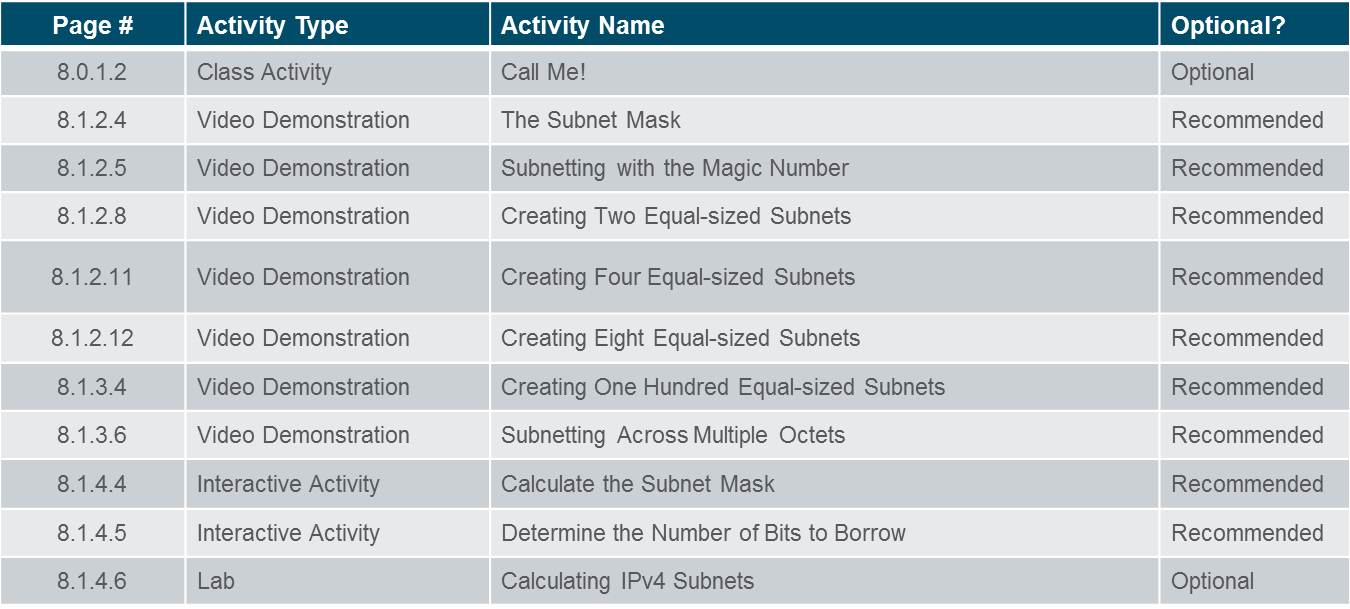
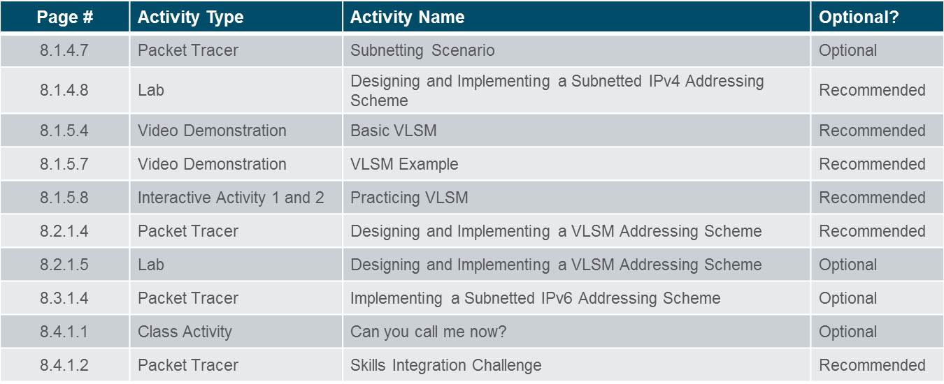
Assessment
Students should complete Chapter 8, “Assessment” after completing Chapter 8.
Quizzes, labs, Packet Tracers and other activities can be used to informally assess student progress.
Sections & Objectives
8.1 Subnetting an IPv4 Network
Implement an IPv4 addressing scheme to enable end-to-end connectivity in a small to medium-sized business network.
Explain how subnetting segments a network to enable better communication.
Explain how to calculate IPv4 subnets for a /24 prefix.
Explain how to calculate IPv4 subnets for a /16 and /8 prefix.
Given a set of requirements for subnetting, implement an IPv4 addressing scheme.
Explain how to create a flexible addressing scheme using variable length subnet masking (VLSM).
8.2 Addressing Schemes
Given a set of requirements, implement a VLSM addressing scheme to provide connectivity to end users in a small to medium-sized network.
Implement a VLSM addressing scheme.
8.3 Address Schemes
Explain design considerations for implementing IPv6 in a business network.
Explain how to implement IPv6 address assignments in a business network.
Chapter 8: Subnetting IP Networks
8.1 – Subnetting an IPv4 Network
8.1.1 – Network Segmentation
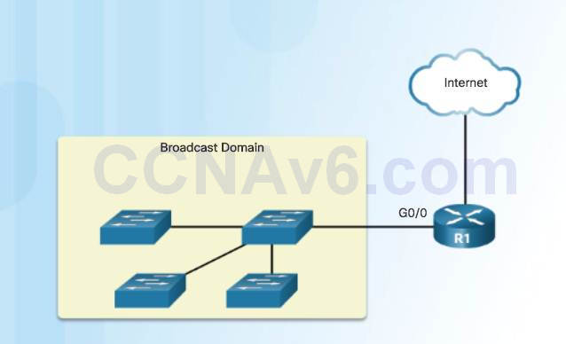
8.1.1.1 – Broadcast Domains
Devices use broadcasts in an Ethernet LAN to locate:
♦ Other devices– Address Resolution Protocol (ARP) which sends Layer 2 broadcasts to a known IPv4 address on the local network to discover the associated MAC address.
♦ Services – Dynamic Host Configuration Protocol (DHCP) which sends broadcasts on the local network to locate a DHCP server.
Switches propagate broadcasts out all interfaces except the interface on which it was received.
8.1.1.2 – Problems with Large Broadcast Domains
Hosts can generate excessive broadcasts and negatively affect the network.
♦ Slow network operations due to the significant amount of traffic it can cause.
♦ Slow device operations because a device must accept and process each broadcast packet.
Solution: Reduce the size of the network to create smaller broadcast domains. These smaller network spaces are called subnets.
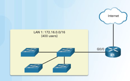
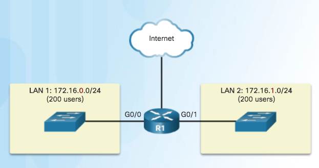
8.1.1.2 – Reasons for Subnetting
Reduces overall network traffic and improves network performance.
Enables an administrator to implement security policies such as which subnets are allowed or not allowed to communicate together.
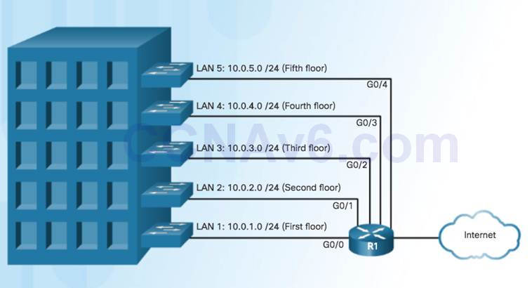
Subnetting by Location
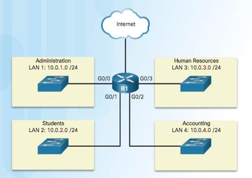
Communicating between
Networks
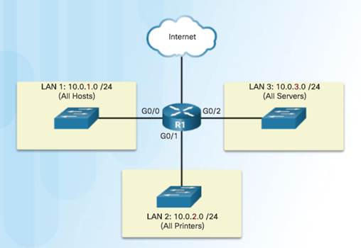
Subnetting by Device Type
8.1.2 – Subnetting an IPv4 Network
8.1.2.1 – Octet Boundaries
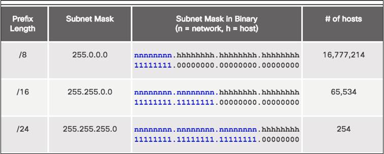
Prefix length and the subnet mask are different ways of identifying the network portion of an address.
Subnets are created by borrowing host bits for network bits.
More host bits borrowed, the more subnets that can be defined.
8.1.2.2 – Subnetting on the Octet Boundary
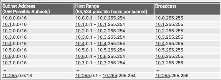
Subnetting Network 10.x.0.0/16
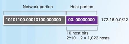
Define up to 256 subnets with each subnet capable of connecting 65,534 hosts.
First two octets identify the network portion while the last two octets are for host IP addresses.
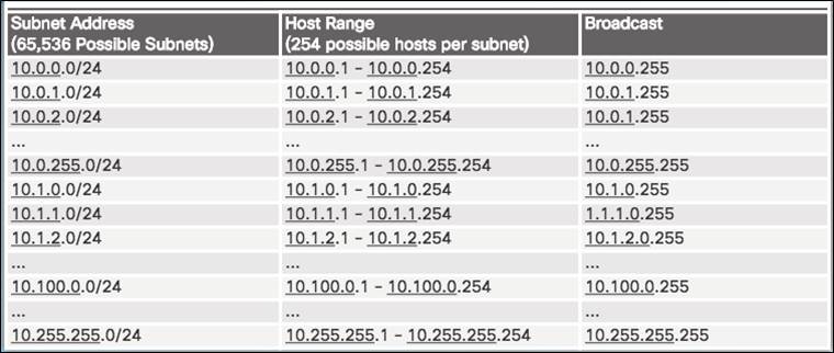
Subnetting Network 10.x.x.0/24
Define 65,536 subnets each capable of connecting 254 hosts.
/24 boundary is very popular in subnetting because of number of hosts.
8.1.2.3 – Classless Subnetting
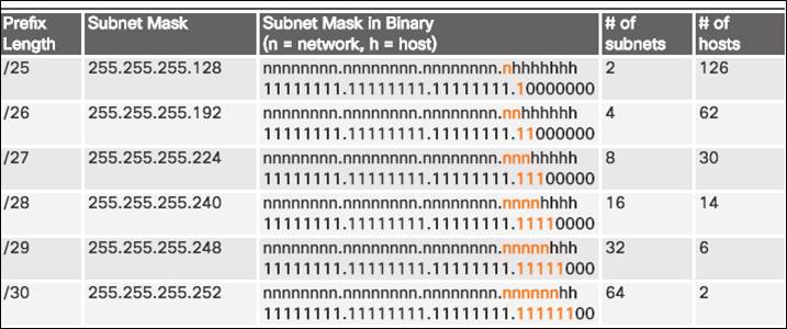
Subnets can borrow bits from any host bit position to create other masks.
8.1.2.4 – Video – The Subnet Mask
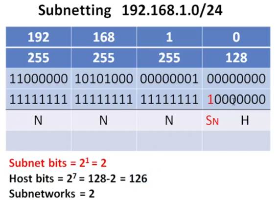
Subnetting in Binary
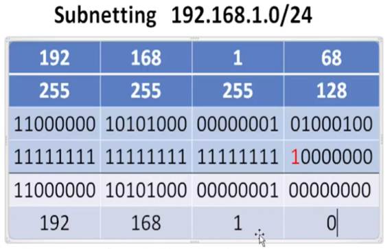
ANDING
♦ Convert IP address and Subnet Mask to Binary (line up vertically like an addition problem)
♦ Logically AND (1 and 1 = 1, all other combinations = 0)
♦ Result is network address for original IP address
Classful Subnetting
♦ Class A /8 255.0.0.0
♦ Class B /16 255.255.0.0
♦ Class C /24 255.255.255.0


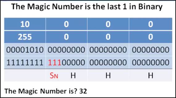
8.1.2.5 – Video – Subnetting with the Magic Number
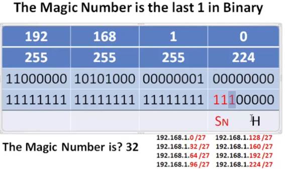
Magic number technique used to calculate subnets
Magic number is simply the place value of the last one in the subnet mask
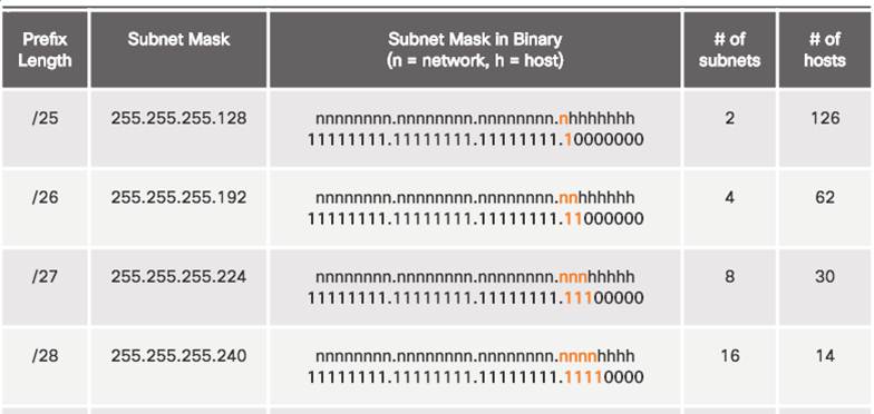
/25 11111111.11111111.11111111.10000000 magic number = 128
/26 11111111.11111111.11111111.11000000 magic number = 64
/27 11111111.11111111.11111111.11100000 magic number = 32

8.1.2.6 – Classless Subnetting Example
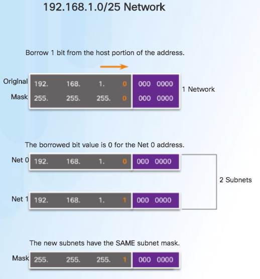
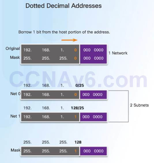
8.1.2.7 – Creating 2 Subnets
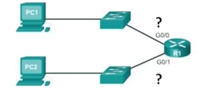
/25 Subnetting Topology
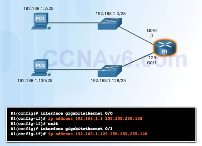
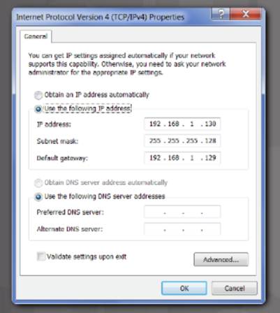
8.1.2.8 – Video Demonstration – Creating Two Equal-sized Subnets (/25)
Create 2 Equal-sized Subnets from 192.168.1.0 /24
Subnet Mask – 11111111.11111111.11111111.10000000

Create 2 Equal-sized Subnets from 192.168.1.0 /24
Subnet Mask – 11111111.11111111.11111111.10000000
Magic Number = 128
192.168.1.0 /25 (start at 0)
192.168.1.128 /25 (Add 128)

8.1.2.9 – Subnetting Formulas
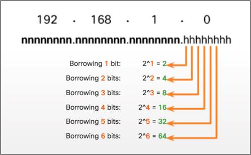
Calculate Number of Subnets Formula
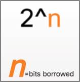
Subnetting a /24 Network
Calculate Number of Hosts Formula
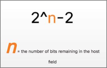
Calculating the Number of Hosts
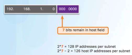
8.1.2.10 – Creating 4 Subnets
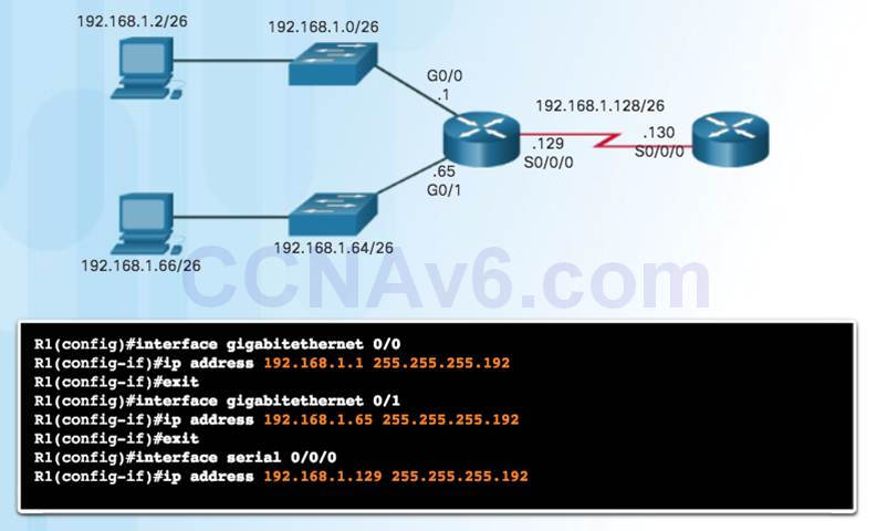
/26 Subnetting Topology
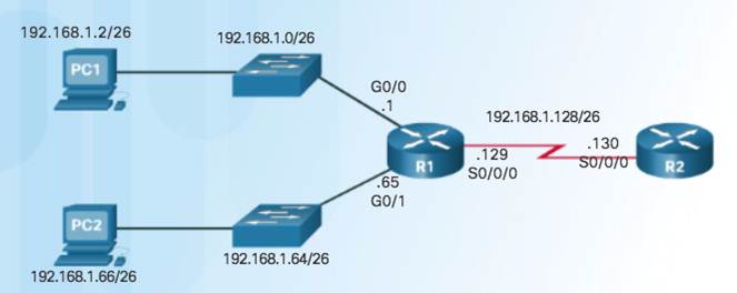
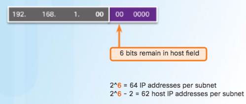
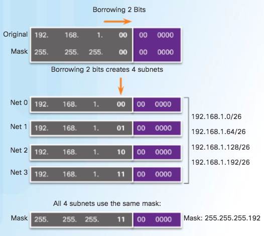
8.1.2.11 – Video Demonstration – Creating Four Equal-sized Subnets (/26)
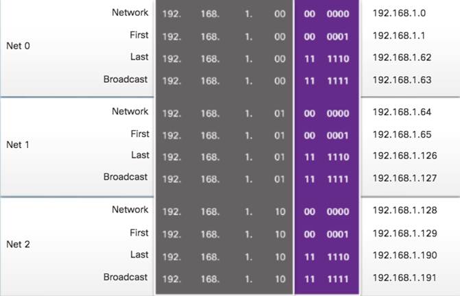
Create 4 Equal-sized Subnets from 192.168.1.0 /24
Subnet Mask in Binary – 11111111.11111111.11111111.11000000
2^2 = 4 Subnets
Magic Number = 64
192.168.1.0 /26
192.168.1.64 /26
192.168.1.128 /26
192.168.1.192 /26
8.1.2.12 – Video Demonstration – Creating Eight Equal-sized Subnets (/27)
Create 8 Equal-sized Subnets from 192.168.1.0 /24
Borrow 3 bits – 11111111.11111111.11111111.11100000
Magic Number = 32
192.168.1.0 /27 (Start at 0)
192.168.1.32 /27 (Add 32 to previous network)
192.168.1.64 /27 (Add 32)
192.168.1.96 /27 (Add 32)
192.168.1.128 /27 (Add 32)
192.168.1.160 /27 (Add 32)
192.168.1.192 /27 (Add 32)
192.168.1.224 /27 (Add 32)

8.1.3 – Subnetting a /16 and /8 Prefix
8.1.3.1 – Creating Subnets with a /16 prefix
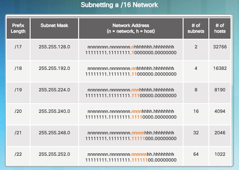
8.1.3.2 – Creating 100 Subnets with a /16 prefix
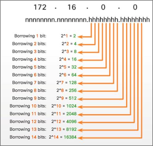
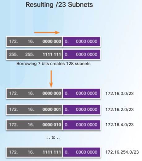
8.1.3.3 – Calculating the Hosts
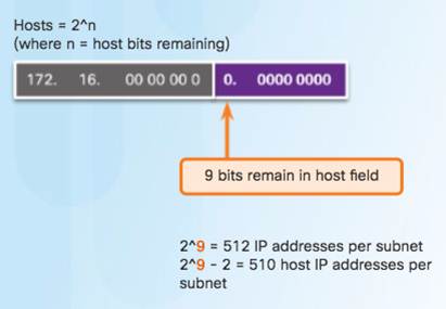
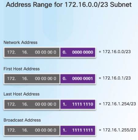
8.1.3.4 – Video Demonstration – Creating One Hundred Equal-sized Subnets
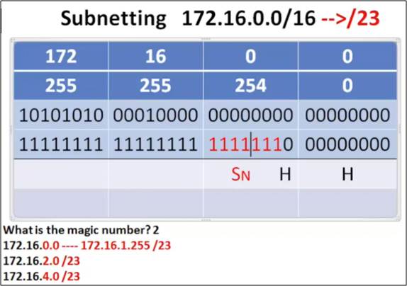
An enterprise network requires 100 equal-sized subnets starting from 172.16.0.0/16
New Subnet Mask
11111111.11111111.11111110.00000000
2^7 = 128 Subnets
2^9 = 512 hosts per subnet
Magic Number = 2
172.16.0.0 /23
172.16.2.0 /23
172.16.4.0 /23
172.16.6.0 /23
…
172.16.254.0 /23

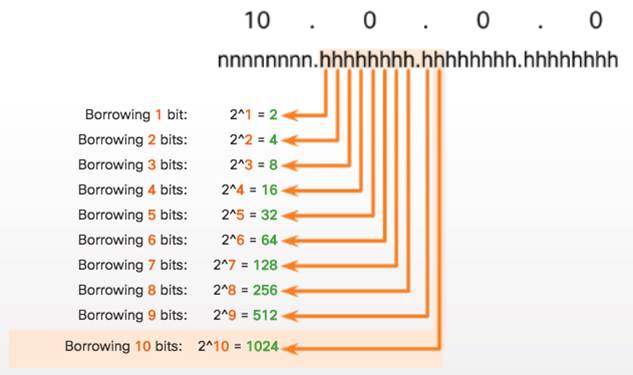
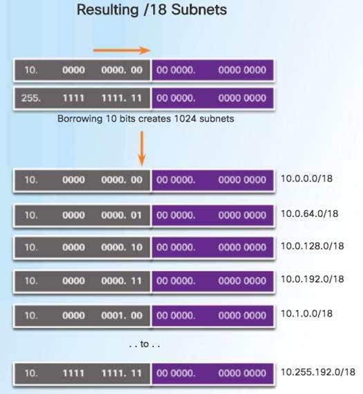
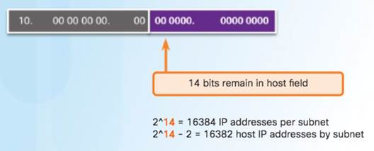
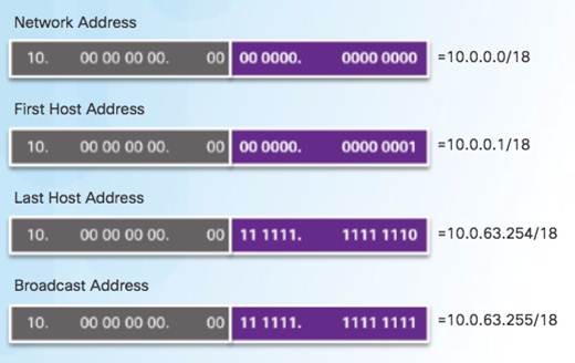
8.1.3.5 – Creating 1000 Subnets with a /8 Network
8.1.3.6 – Video Demonstration – Subnetting Across Multiple Octets


New Challenge Problem: Create over 300 Equal-sized Subnets of 20,000 Hosts each starting from 10.0.0.0/8
8.1.4 – Subnetting to Meet Requirements
8.1.4.1 – Subnetting Based on Host Requirements
8.1.4.2 – Subnetting Based On Network Requirements
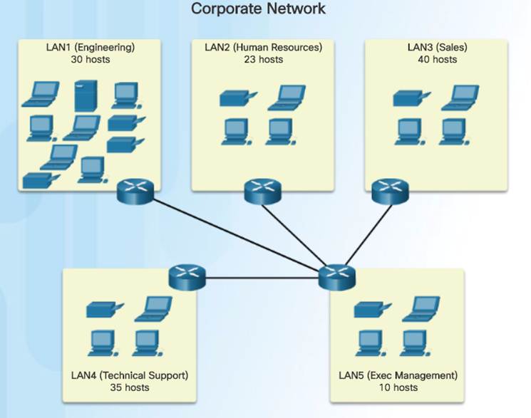
Host devices used by employees in the Engineering department in one network and Management in a separate network.

8.1.4.3 – Network Requirement Example
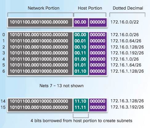
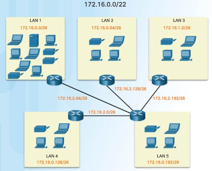
8.1.4.6 – Lab – Calculating IPv4 Subnets
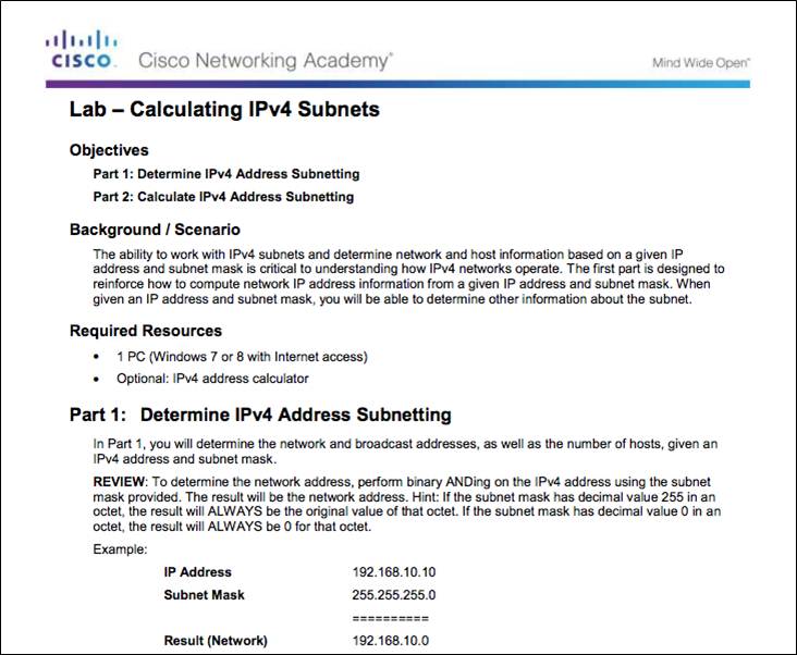
8.1.4.6 Lab – Calculating IPv4 Subnets
8.1.4.7 – Packet Tracer – Subnetting Scenario
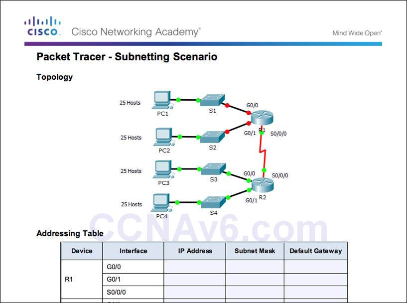
8.1.4.7 Packet Tracer – Subnetting Scenario 1
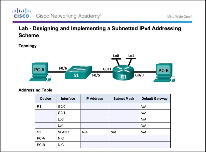
8.1.4.8 – Lab – Designing and Implementing a Subnetted IPv4 Addressing Scheme
8.1.4.8 Lab – Designing and Implementing a Subnetted IPv4 Addressing Scheme
8.1.5 – Benefits of Variable Length Subnet Masking
8.1.5.1– Traditional Subnetting Wastes Addresses
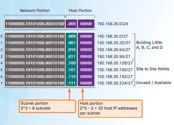

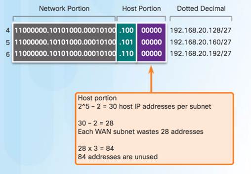
8.1.5.2 – Variable Length Subnet Masks (VLSM)
Traditional
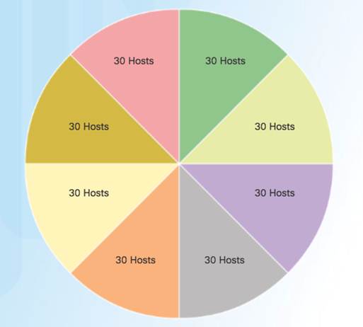
Subnets of Varying Sizes
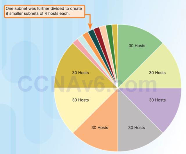
8.1.5.3 – Basic VLSM
Basic Subnetting
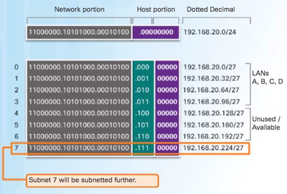
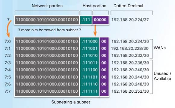
8.1.5.4 – Video Demonstration – VLSM Basics
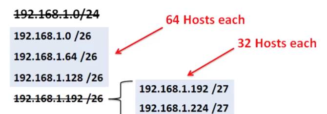
Basic VLSM
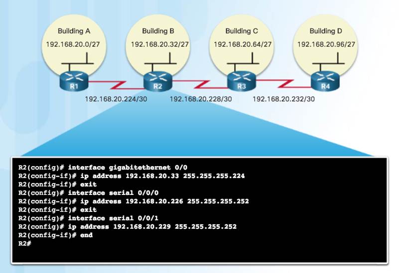
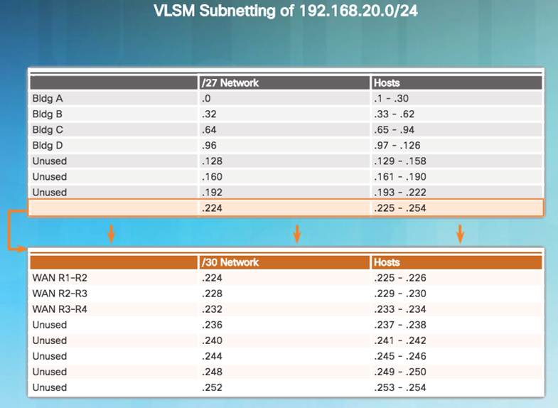
♦ Subnets do not have to be equal sizes, as long as their address ranges do not overlap.
♦ When creating subnets it is easier to work from larger to smaller.
8.1.5.5 – VLSM in Practice
8.1.5.6 – VLSM Chart
8.1.5.7 – Video Demonstration – VLSM Example
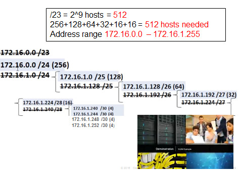
Given the network 172.16.0.0 /23 creates subnets:
1 network for 200 hosts – 256
1 network for 100 hosts – 128
1 network for 50 hosts – 64
1 network for 25 hosts – 32
1 network for 10 hosts – 16
4 point-to-point networks for 2 hosts each – 4×4 = 16
8.2 – Addressing Schemes
8.2.1 – Structured Design
8.2.1.1 – Network Address Planning
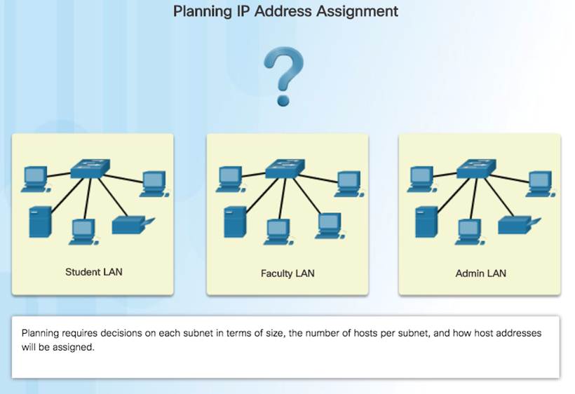
8.2.1.2 – Planning to Address the Network
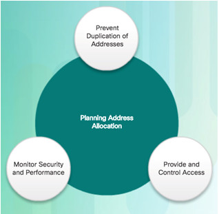
Each host in an internetwork must have a unique address.
Need proper planning & documentation.
Must provide & control access to servers from internal hosts and external hosts.
Layer 3 STATIC address assigned to a server can be used to control access to that server.
Monitoring security and performance of hosts means network traffic is examined for source IP addresses that are generating or receiving excessive packets.
8.2.1.3 – Assigning Addresses to Devices
Devices that require addresses:
End user clients
Can be set for DHCP to save time and manual errors.
A change in the subnetting scheme requires reconfiguration of DHCP server. IPv6 clients use DHCPv6/SLAAC.
Servers
Configured with static addresses.
Private addresses translated to public addresses if accessible from the Internet.
Intermediary devices
Set with static addresses for remote management.
Gateway
Router interface used to exit the network.

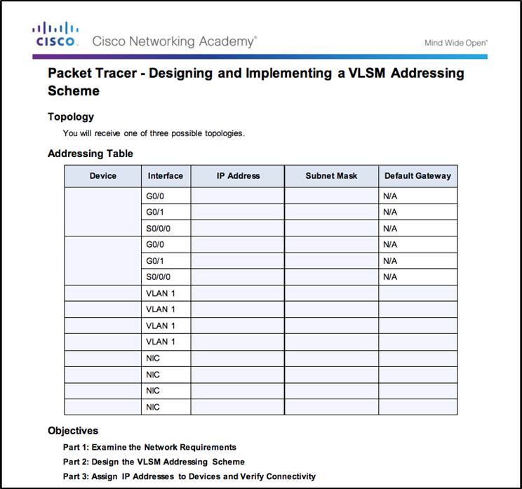
8.2.1.4 – Packet Tracer – Designing and Implementing a VLSM Addressing Scheme
8.2.1.4 Packet Tracer – Designing and Implementing a VLSM Addressing Scheme
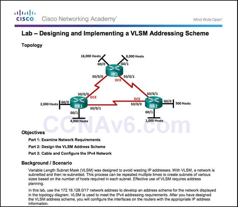
8.2.1.5 – Lab – Designing and Implementing a VLSM Addressing Scheme
8.2.1.5 Lab – Designing and Implementing a VLSM Addressing Scheme
8.3 – Design Considerations for IPv6
8.3.1 – Subnetting an IPv6 Network
8.3.1.1 – The IPv6 Global Unicast Address
IPv6 subnetting is not concerned with conserving address space.
IPv6 subnetting is about building an addressing hierarchy based on the number of subnetworks needed.
IPv6 link-local address is never subnetted.
IPv6 global unicast address can be subnetted.
IPv6 global unicast address normally consists of a /48 global routing prefix, a 16 bit subnet ID, and a 64 bit interface ID.
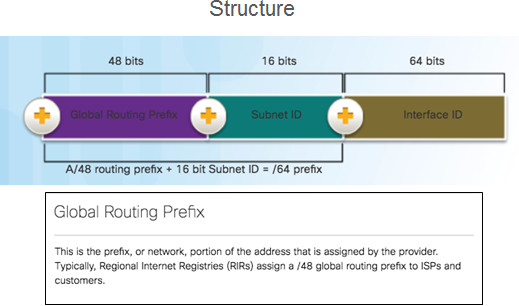
8.3.1.2 – Subnetting Using the Subnet ID
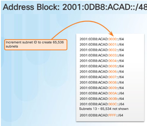
8.3.1.3 – IPv6 Subnet Allocation
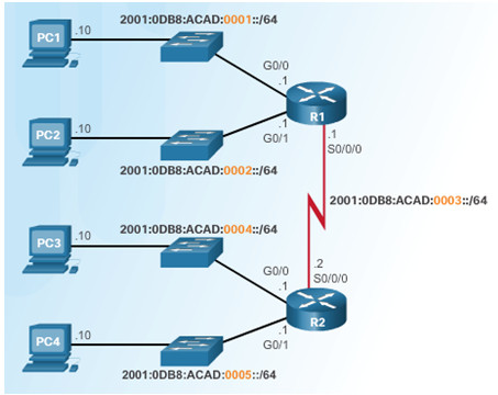
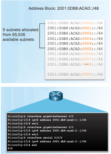
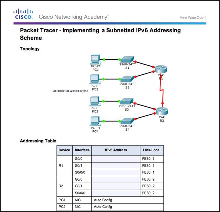
8.3.1.4 – Packet Tracer – Implementing a Subnetted IPv6 Addressing Scheme
8.3.1.4 Packet Tracer – Implementing a Subnetted IPv6 Addressing Scheme
8.4 – Summary
8.4.1 – Conclusion
8.4.1.1 Class Activity – Can You Call Me Now?
8.4.1.1 Class Activity – Can You Call Me Now?
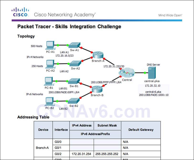
8.4.1.2 – Packet Tracer – Skils Integration Challenge
8.4.1.2 Packet Tracer – Skills Integration Challenge
8.4.1.3 – Subnetting IP Networks
Implement an IPv4 addressing scheme to enable end-to-end connectivity in a small to medium-sized business network.
Given a set of requirements, implement a VLSM addressing scheme to provide connectivity to end users in a small to medium-sized network.
Explain design considerations for implementing IPv6 in a business network.
New Terms and Commands
octet boundary
Variable Length Subnet Masking (VLSM)
