Instructor Planning Guide
Activities
What activities are associated with this chapter?
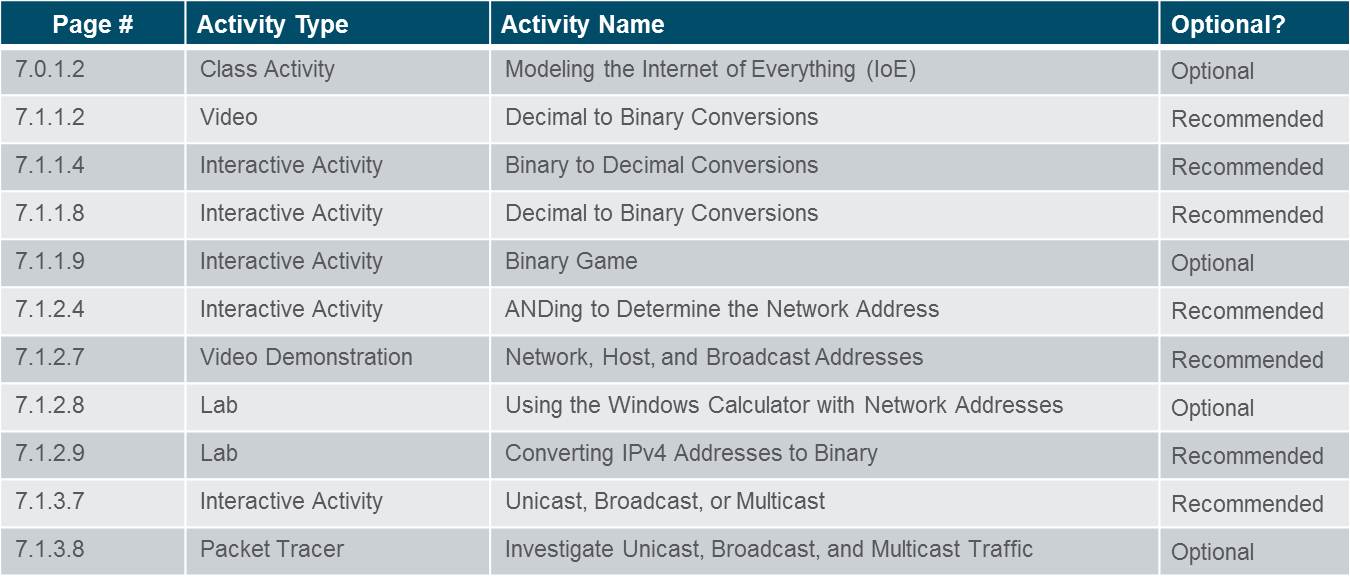
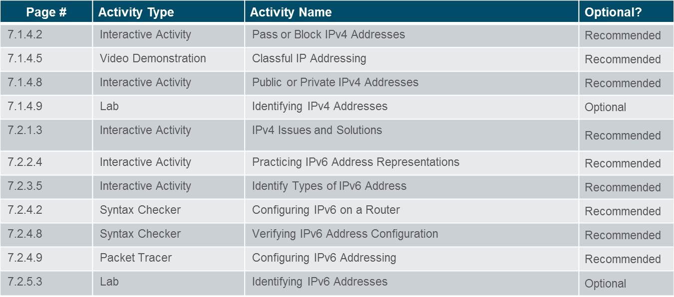
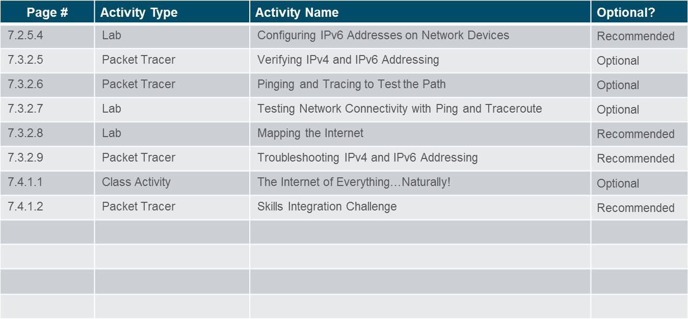
Assessment
Students should complete Chapter 7, “Assessment” after completing Chapter 7.
Quizzes, labs, Packet Tracers and other activities can be used to informally assess student progress.
Sections & Objectives
7.1 IPv4 Network Addresses
Explain the use of IPv4 addresses to provide connectivity in small to medium-sized business networks
Convert between binary and decimal numbering systems.
Describe the structure of an IPv4 address including the network portion, the host portion, and the subnet mask.
Compare the characteristics and uses of the unicast, broadcast and multicast IPv4 addresses.
Explain public, private, and reserved IPv4 addresses.
7.2 IPv6 Network Addresses
Configure IPv6 addresses to provide connectivity in small to medium-sized business networks.
Explain the need for IPv6 addressing.
Describe the representation of an IPv6 address.
Compare types of IPv6 network addresses.
Configure global unicast addresses.
Describe multicast addresses.
7.3 Connectivity Verification
Use common testing utilities to verify and test network connectivity.
Explain how ICMP is used to test network connectivity.
Use ping and traceroute utilities to test network connectivity.
Chapter 7: IP Addressing
7.1 – IPv4 Network Addresses
7.1.1 – Binary and Decimal Conversion
7.1.1.1 IPv4 Addresses
Binary numbering system consists of the numbers 0 and 1 called bits
IPv4 addresses are expressed in 32 binary bits divided into 4 8-bit octets
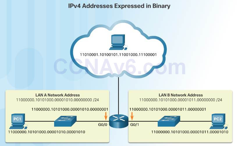
IPv4 addresses are commonly expressed in dotted decimal notation
7.1.1.2–Video Demonstration – Converting Between Binary and Decimal Numbering System
This video will cover the process of ANDing as it relates to discovering the network address, the host addresses, and the broadcast address in an IPv4 network.
7.1.1.3 Positional Notation
The first row identifies the number base or radix. Decimal is 10. Binary is based on 2, therefore radix will be 2
The 2nd row considers the position of the number starting with 0. These numbers also represent the exponential value that will be used to calculate the positional value (4th row).
The 3rd row calculates the positional value by taking the radix and raising it by the exponential value of its position. Note: n^0 is always = 1.
The positional value is listed in the fourth row.
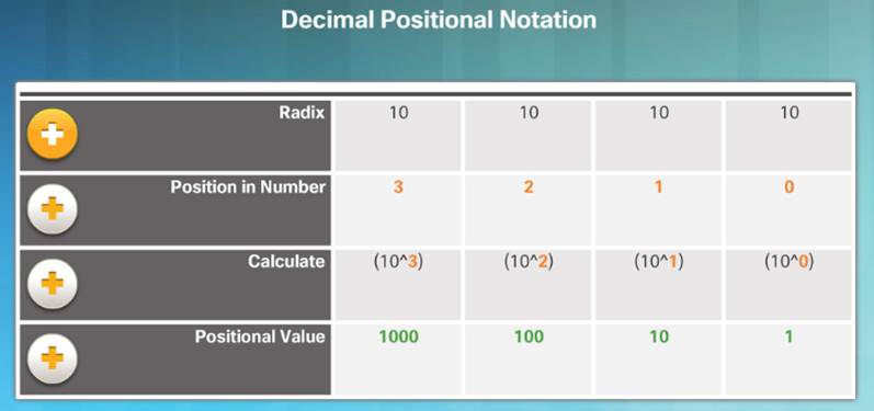
Applying decimal positional notation

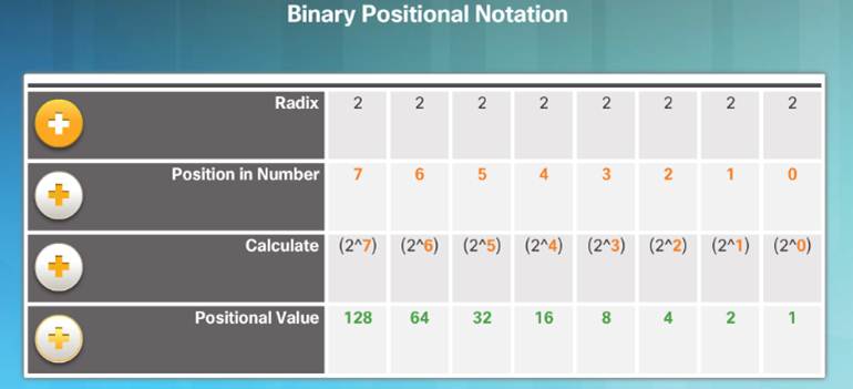
Applying binary positional notation.

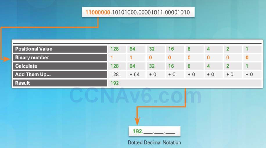
7.1.1.4 Binary to Decimal Conversion
To convert a binary IPv4 address to decimal enter the 8-bit binary number of each octet under the positional value of row 1 and then calculate to produce the decimal.
7.1.1.6 Decimal to Binary Conversion
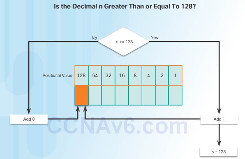
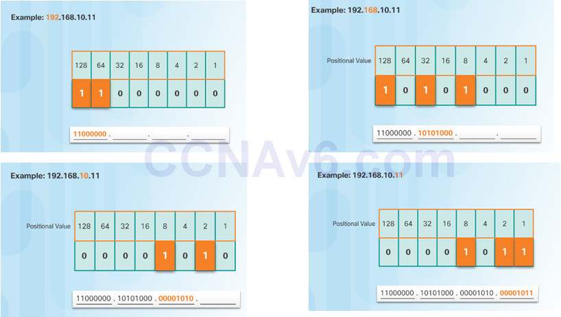
To convert a decimal IPv4address to binary use the positional chart and check first if the number is greater than the 128 bit. If no a 0 is placed in this position. If yes then a 1 is placed in this position.
128 is subtracted from the original number and the remainder is then checked against the next position (64) If it is less than 64 a 0 is placed in this position. If it is greater, a 1 is placed in this position and 64 is subtracted.
The process repeats until all positional values have been entered.
7.1.1.7 Decimal to Binary Conversion Examples
7.1.2 – IPv4 Address Structure
7.1.2.1 Network and Host Portions
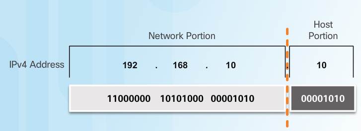
An IPv4 address is hierarchical.
♦ Composed of a Network portion and Host portion.
All devices on the same network must have the identical network portion.
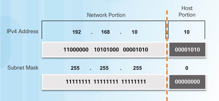
The Subnet Mask helps devices identify the network portion and host portion.
7.1.2.2 -The Subnet Mask
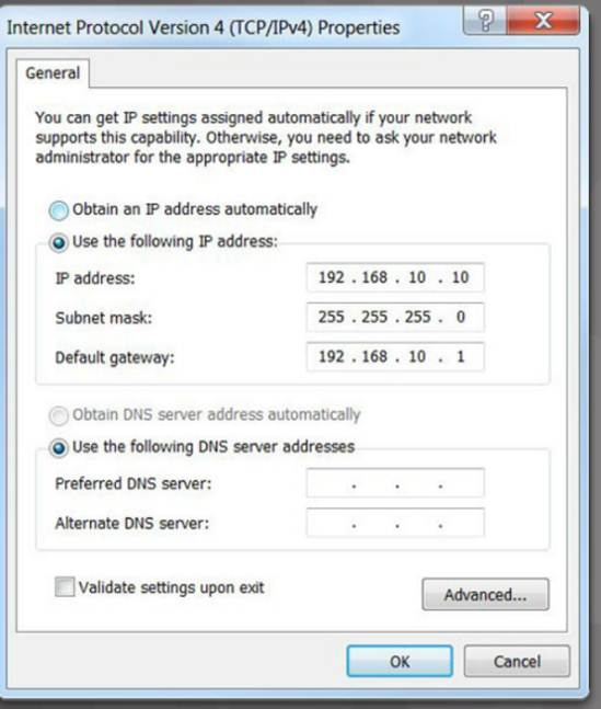
Three IPv4 addresses must be configured on a host:
♦ Unique IPv4 address of the host.
♦ Subnet mask – identifies the network/host portion of the IPv4 address.
♦ Default gateway -IP address of the local router interface.
The IPv4 address is compared to the subnet mask bit by bit, from left to right.
A 1 in the subnet mask indicates that the corresponding bit in the IPv4 address is a network bit.
7.1.2.3 -Logical AND
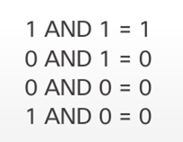
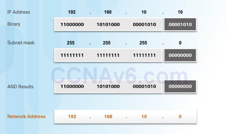
A logical AND is one of three basic binary operations used in digital logic.
Used to determine the Network Address
The Logical AND of two bits yields the following results:
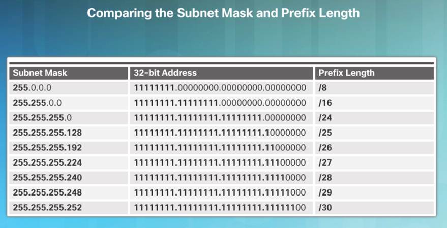
7.1.2.5 – The Prefix Length
The Prefix Length:
♦ Shorthand method of expressing the subnet mask.
♦ Equals the number of bits in the subnet mask set to 1.
♦ Written in slash notation, / followed by the number of network bits.
7.1.2.6 – Network, Host, and Broadcast Addresses
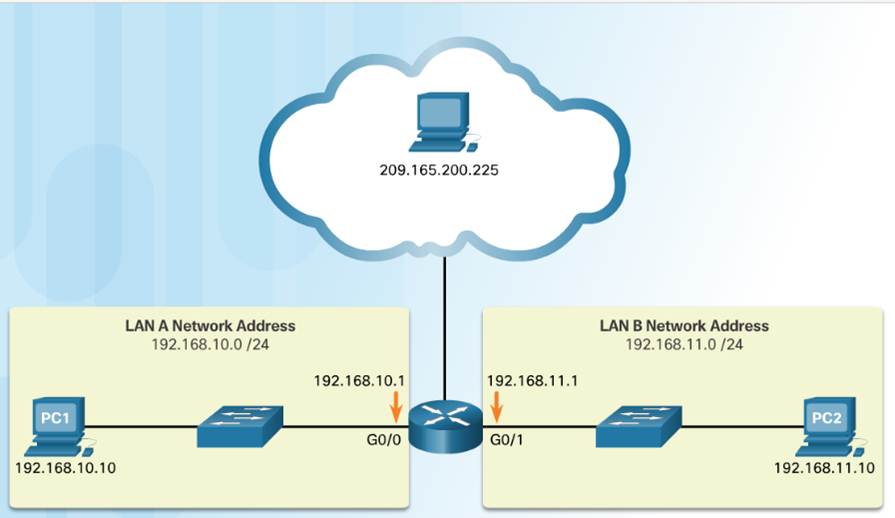
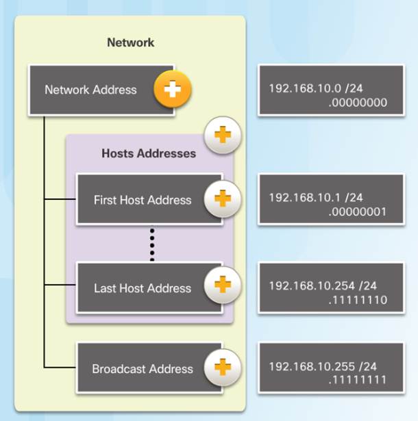
Types of Addresses in Network 192.168.10.0/24
♦ Network Address – host portion is all 0s (.00000000)
♦ First Host address – host portion is all 0s and ends with a 1 (.00000001)
♦ Last Host address – host portion is all 1s and ends with a 0 (.11111110)
♦ Broadcast Address – host portion is all 1s (.11111111)
7.1.2.7 – Video Demonstration – Network, Host, and Broadcast Addresses
This video will cover the process of ANDing as it relates to discovering the network address, the host addresses, and the broadcast address in an IPv4 network.
7.1.2.8 – Lab – Using the Windows Calculator with Network Addresses
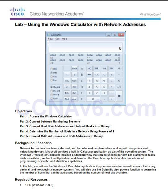
7.1.2.8 Lab – Using the Windows Calculator with Network Addresses
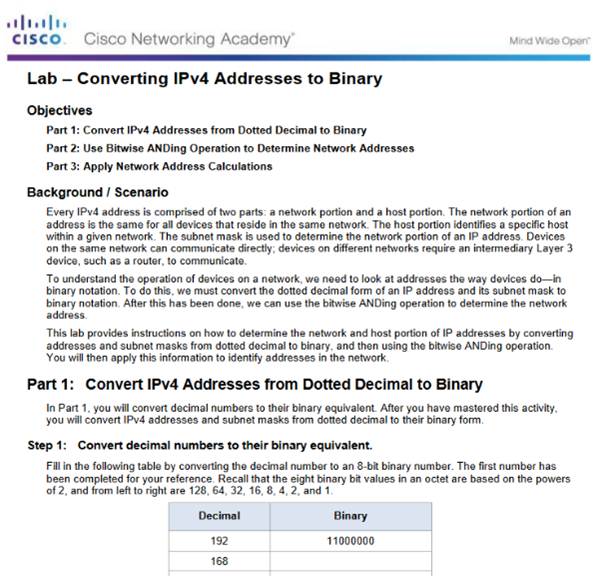
7.1.2.9 – Lab – Converting IPv4 Addresses to Binary
7.1.2.9 Lab – Converting IPv4 Addresses to Binary
7.1.3 – IPv4 Unicast, Broadcast, and Multicast
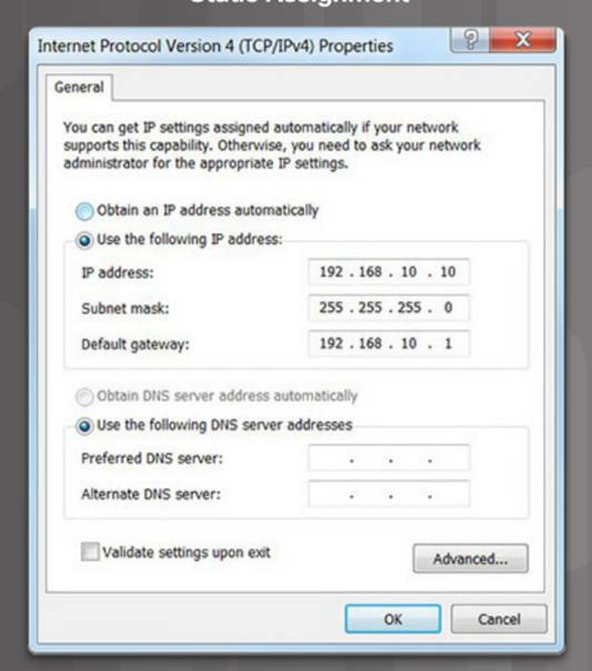
7.1.3.1 – Static IPv4 Address Assignment to a Host
Some devices like printers, servers and network devices require a fixed IP address.
Hosts in a small network can also be configured with static addresses.
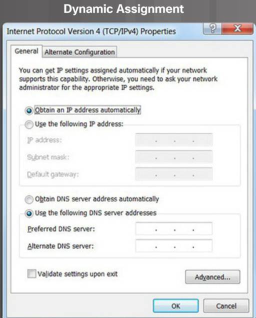
7.1.3.2 – Dynamic IPv4 Address Assignment to a Host
Most networks use Dynamic Host Configuration Protocol (DHCP) to assign IPv4 addresses dynamically.
The DHCP server provides an IPv4 address, subnet mask, default gateway, and other configuration information.
DHCP leases the addresses to hosts for a certain length of time.
If the host is powered down or taken off the network, the address is returned to the pool for reuse.
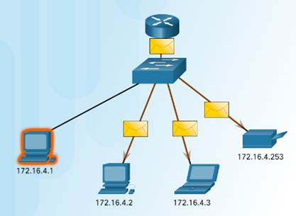
7.1.3.3 – IPv4 Communication
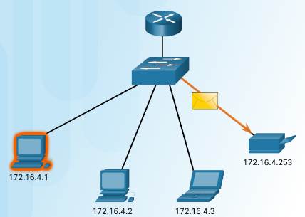
Unicast – one to one communication.
Broadcast– one to all.
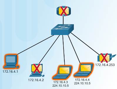
Multicast – one to a select group.
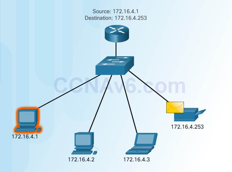
7.1.3.4 – Unicast Transmission
Unicast – one to one communication.
♦ Use the address of the destination device as the destination address.
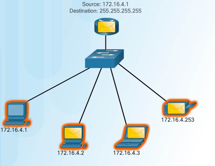
7.1.3.5 – Broadcast Transmission
Broadcast– one to all
♦ Message sent to everyone in the LAN (broadcast domain.)
♦ destination IPv4 address has all ones (1s) in the host portion.
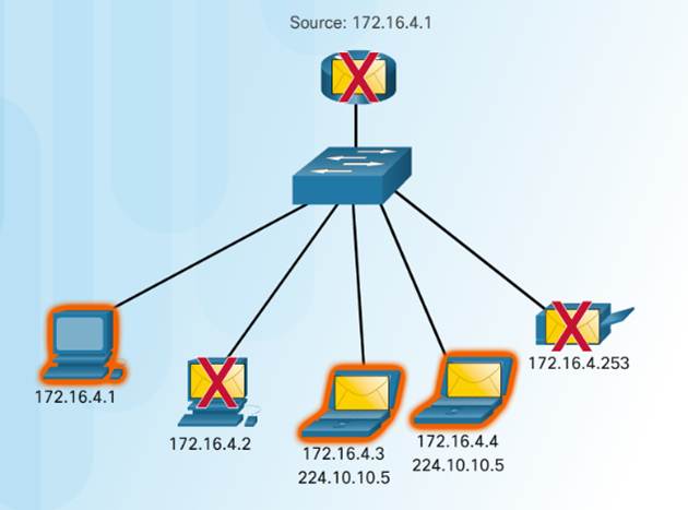
7.1.3.6 – Multicast Transmission
Multicast– one to a select group.
♦ 224.0.0.0 to 239.255.255.255 addresses reserved for multicast.
♦ routing protocols use multicast transmission to exchange routing information.
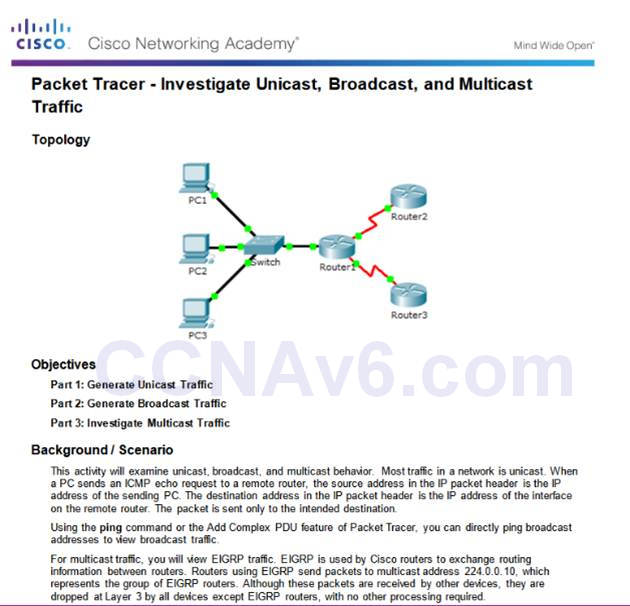
7.1.3.8 – Packet Tracer – Investigate Unicast, Broadcast, and Multicast Traffic
7.1.3.8 Packet Tracer – Investigate Unicast, Broadcast, and Multicast Traffic
7.1.4 – Types of IPv4 Addresses
7.1.4.1 – Public and Private IPv4 Addresses
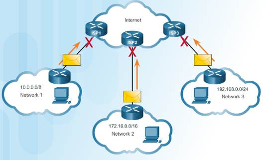
Private Addresses:
Not routable
Introduced in mid 1990s due to depletion of IPv4 addresses
Used only in internal networks.
Must be translated to a public IPv4 to be routable.
Defined by RFC 1918
Private Address Blocks:
10.0.0.0 /8 or 10.0.0.0 to 10.255.255.255
172.16.0.0 /12 or 172.16.0.0 to 172.31.255.255192.168.0.0 /16
192.168.0.0 to 192.168.255.255
7.1.4.3 – Special User IPv4 Addresses
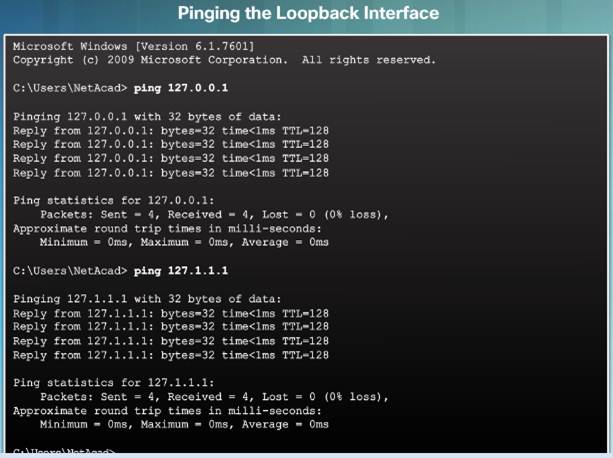
Loopback addresses (127.0.0.0 /8 or 127.0.0.1)
♦ Used on a host to test if the TCP/IP configuration is operational.
Link-Local addresses (169.254.0.0 /16 or 169.254.0.1)
♦ Commonly known as Automatic Private IP Addressing (APIPA) addresses.
♦ Used by Windows client to self configure if no DHCP server available.
TEST-NET addresses (192.0.2.0/24 or 192.0.2.0 to 192.0.2.255)
♦ Used for teaching and learning.
7.1.4.4 – Legacy Classful Addressing
In 1981, Internet IPv4 addresses were assigned using classful addressing (RFC 790)
Network addresses were based on 3 classes:
♦ Class A (0.0.0.0/8 to 127.0.0.0/8) – Designed to support extremely large networks with more than 16 million host addresses.
♦ Class B (128.0.0.0 /16 – 191.255.0.0 /16) – Designed to support the needs of moderate to large size networks up to approximately 65,000 host addresses.
♦ Class C (192.0.0.0 /24 – 223.255.255.0 /24) – Designed to support small networks with a maximum of 254 hosts.
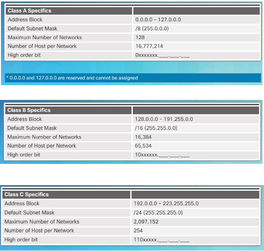
7.1.4.5 – Video Demonstration – Classful IPv4 Addressing
Discussion of Classful Addressing
♦ Identifying a Classful address by the IP address and the subnet mask

7.1.4.6 – Classless Addressing
Classful Addressing wasted addresses and exhausted the availability of IPv4 addresses.
Classless Addressing Introduced in the 1990s
♦ Classless Inter-Domain Routing (CIDR, pronounced “cider”)
♦ Allowed service providers to allocate IPv4 addresses on any address bit boundary (prefix length) instead of only by a class A, B, or C.
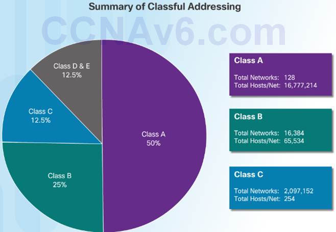
7.1.4.7 – Assignment of IP Addresses
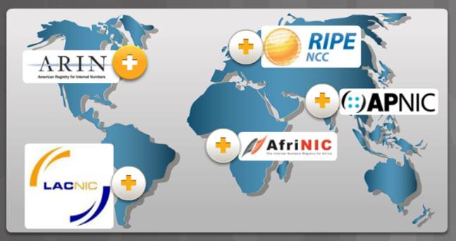
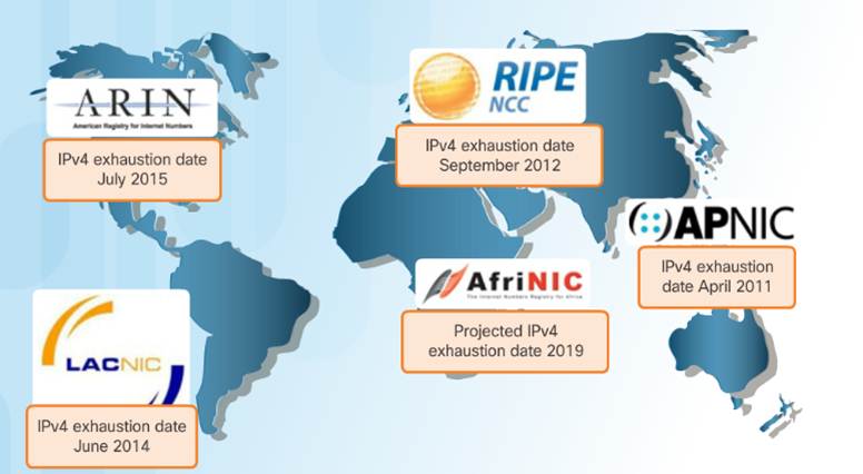
The following organizations manage and maintain IPv4 and IPv6 addresses for the various regions.
American Registry for Internet Numbers (ARIN)- North America.
Réseaux IP Europeans (RIPE) – Europe, the Middle East, and Central Asia
Asia Pacific Network Information Centre (APNIC) – Asia and Pacific regions
African Network Information Centre (AfriNIC) – Africa
Regional Latin-American and Caribbean IP Address Registry (LACNIC) – Latin America and some Caribbean islands
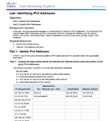
7.1.4.9 – Lab – Identifying IPv4 Addresses
7.1.4.9 Lab – Identifying IPv4 Addresses
7.2 – IPv6 Network Addresses
7.2.1– IPv4 Issues
7.2.1.1 – The Need for IPv6
IPv6 versus IPv4:
♦ Has a larger 128-bit address space
♦ 340 undecillion addresses
♦ Solves limitations with IPv4
♦ Adds enhancement like address auto-configuration.
Why IPv6 is needed:
♦ Rapidly increasing Internet population
♦ Depletion of IPv4
♦ Issues with NAT
♦ Internet of Things
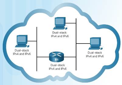
7.2.1.2 – IPv4 and IPv6 Coexistence
Dual stack – Devices run both IPv4 and IPv6 protocol stacks simultaneously.
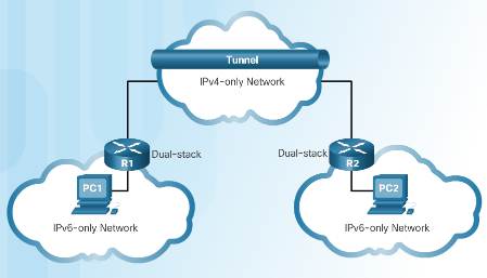
Tunneling – The IPv6 packet is encapsulated inside an IPv4 packet.
Translation – Network Address Translation 64 (NAT64) allows IPv6-enabled devices to communicate with IPv4 devices.
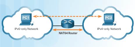
7.2.2– IPv6 Addressing
7.2.2.1 – IPv6 Address Representation
IPv6 Addresses:
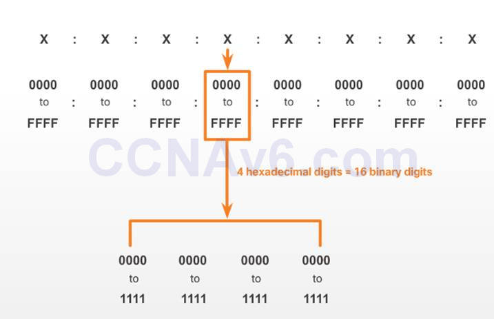
♦ 128 bits in length
♦ Every 4 bits is represented by a single hexadecimal digit
♦ Hextet – unofficial term referring to a segment of 16 bits or four hexadecimal values.
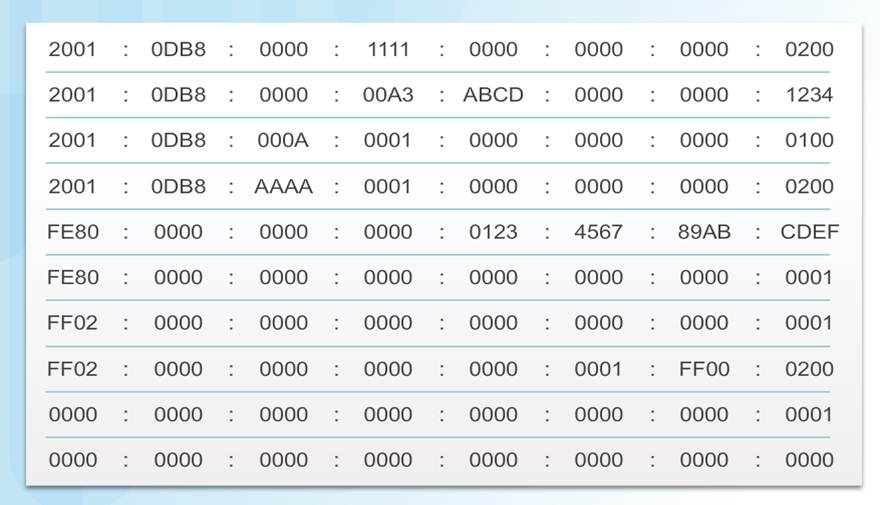
Preferred format for IPv6 representation
7.2.2.2 – Rule 1 – Omit Leading 0s
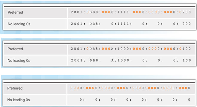
In order to reduce or compress IPv6
♦ First rule is to omit leading zeros in any hextet.
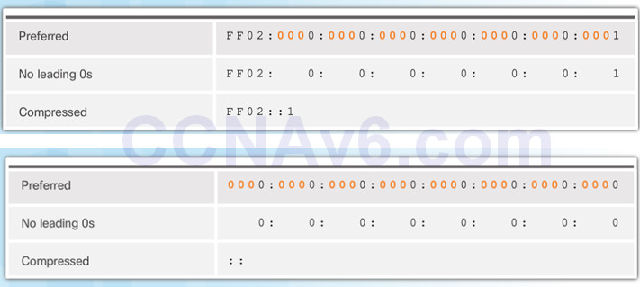
7.2.2.3 – Rule 2 – Omit All 0 Segments
Rule 2 – Omit All 0 Segments
♦ A double colon (::) can replace any single, contiguous string of one or more 16-bit segments (hextets) consisting of all 0s.
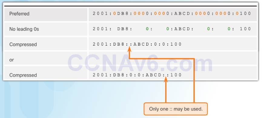
Rule 2 – Omit All 0 Segments
♦ A double colon (::) can replace any single, contiguous string of one or more 16-bit segments (hextets) consisting of all 0s.
7.2.3 – Types of IPv6 Addresses
7.2.3.1 – IPv6 Address Types
Three types of IPv6 addresses:
♦ Unicast– Single source IPv6 address.
♦ Multicast – An IPv6 multicast address is used to send a single IPv6 packet to multiple destinations.
♦ Anycast – An IPv6 anycast address is any IPv6 unicast address that can be assigned to multiple devices.
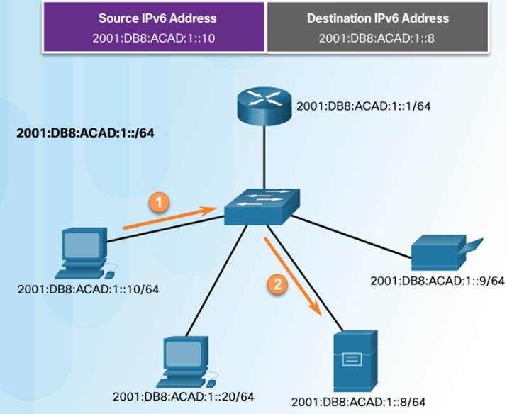
7.2.3.2 – IPv6 Prefix Length
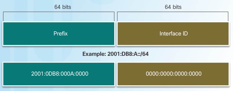
The IPv6 prefix length is used to indicate the network portion of an IPv6 address:
♦ The prefix length can range from 0 to 128.
♦ Typical IPv6 prefix length for most LANs is /64
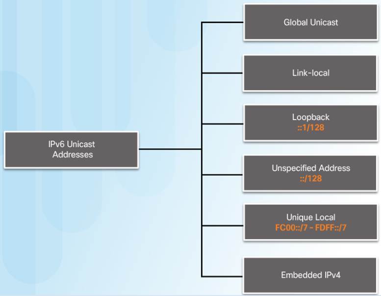
7.2.3.3 – IPv6 Unicast Addresses
Global Unicast – These are globally unique, Internet routable addresses.
Link-local – used to communicate with other devices on the same local link. Confined to a single link.
Unique Local – used for local addressing within a site or between a limited number of sites.
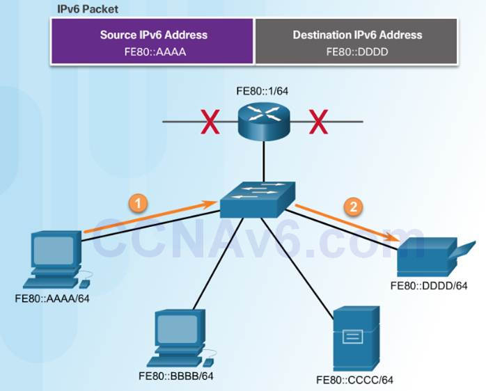
7.2.3.4 – IPv6 Link-Local Unicast Addresses
IPv6 link-local addresses:
♦ Enable a device to communicate with other IPv6-enabled devices on the same link only.
♦ Are created even if the device has not been assigned a global unicast IPv6 address.
♦ Are in the FE80::/10 range.
Note: Typically, it is the link-local address of the router that is used as the default gateway for other devices on the link.
7.2.4 – IPv6 Unicast Addresses
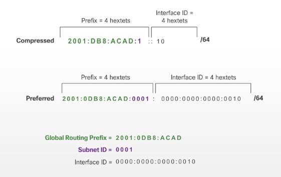
7.2.4.1 – Structure of an IPv6 Global Unicast Address
Currently, only global unicast addresses with the first three bits of 001 or 2000::/3 are being assigned

A global unicast address has three parts:
♦ Global routing prefix – network, portion of the address that is assigned by the provider. Typically /48.
♦ Subnet ID – Used to subnet within an organization.
♦ Interface ID – equivalent to the host portion of an IPv4 address.
7.2.4.2 – Static Configuration of a Global Unicast Address
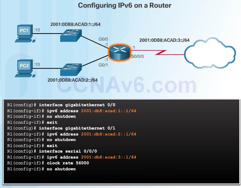
Router Configuration:
♦ Similar commands to IPv4, replace IPv4 with IPv6
♦ Command to configure andIPv6 global unicast on an interface is ipv6 address ipv6-address/prefix-length
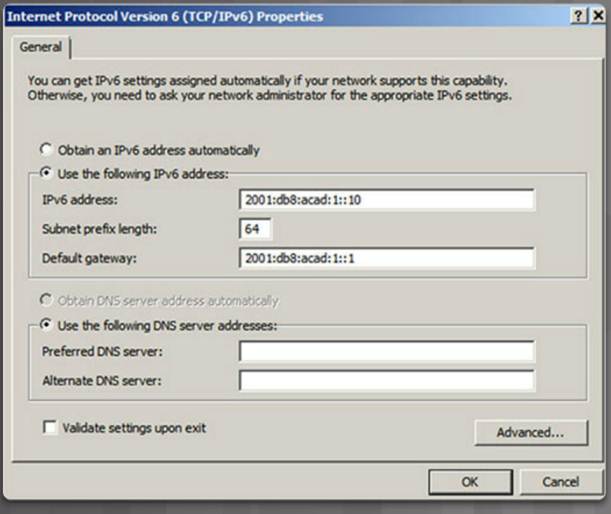
Host Configuration:
♦ Manually configuring the IPv6 address on a host is similar to configuring an IPv4 address
♦ Default gateway address can be configured to match the link-local or global unicast address of the Gigabit Ethernet interface.
Dynamic assignment of IPv6 addresses:
♦ Stateless Address Autoconfiguration (SLAAC)
♦ Stateful DHCPv6
7.2.4.3 – Dynamic Configuration – SLAAC
Stateless Address Autoconfiguration (SLAAC):
♦ A device can obtain its prefix, prefix length, default gateway address, and other information from an IPv6 router.
♦ Uses the local router’s ICMPv6 Router Advertisement (RA) messages
ICMPv6 RA messages sent every 200 seconds to all IPv6-enabled devices on the network.
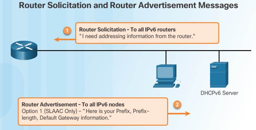
Option 1 (SLAAC Only) – “I’m everything you need (Prefix, Prefix-length, Default Gateway)”
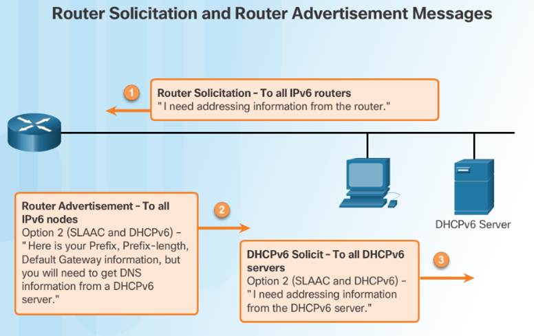
Option 2 (SLAAC and DHCPv6) – “Here is my information but you need to get other information such as DNS addresses from a DHCPv6 server.”
Option 3 (DHCPv6 Only) – “I can’t help you. Ask a DHCPv6 server for all your information.”
7.2.4.4 – Dynamic Configuration – DHCPv6
The RA Option 1: SLAAC only (this is the default)
RA Option 2: SLAAC and Stateless DHCPv6:
♦ Uses SLAAC for IPv6 global unicast address and default gateway.
♦ Uses a stateless DHCPv6 server for other information.
RA Option 3: Stateful DHCPv6
♦ Uses the Routers link-local address for the default gateway.
♦ Uses DHCPv6 for all other information.
7.2.4.5 – EUI-64 Process and Randomly Generated
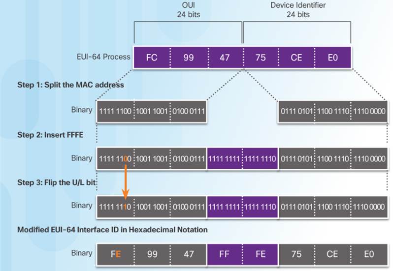
When the RA message is SLAAC or SLAAC with stateless DHCPv6, the client must generate its own Interface ID
♦ The Interface ID can be created using the EUI-64 process or a randomly generated 64-bit number
An EUI-64 Interface ID is represented in binary and is made up of three parts:
♦ 24-bit OUI from the client MAC address, but the 7th bit (the Universally/Locally (U/L) bit) is reversed.
♦ The inserted 16-bit value FFFE (in hexadecimal).
♦ 24-bit Device Identifier from the client MAC address.
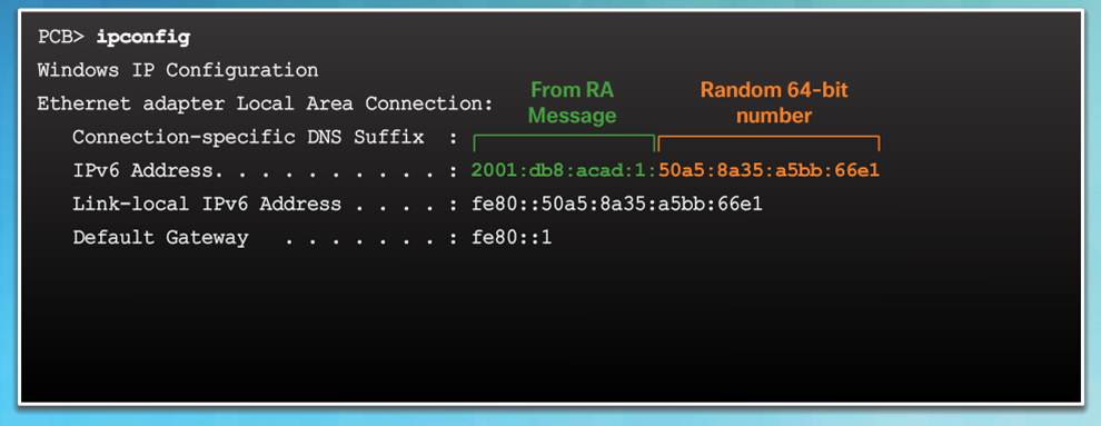
Randomly Generated Interface IDs
♦ Windows uses a randomly generated Interface ID
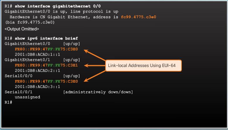
7.2.4.6 – Dynamic Link-Local Addresses
Link-local address can be established dynamically or configured manually.
Cisco IOS routers use EUI-64 to generate the Interface ID for all link-local address on IPv6 interfaces.
Drawback to using the dynamically assigned link-local address is the long interface ID, therefore they are often configured statically.
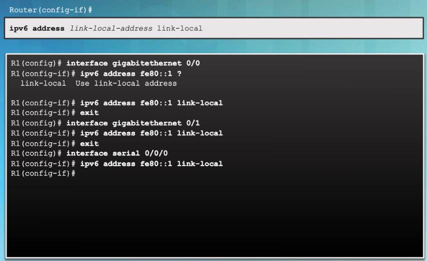
7.2.4.7 – Static Link-Local Addresses
Manual Configuration of the link-local address allows the creation of a simple, easy to remember address.
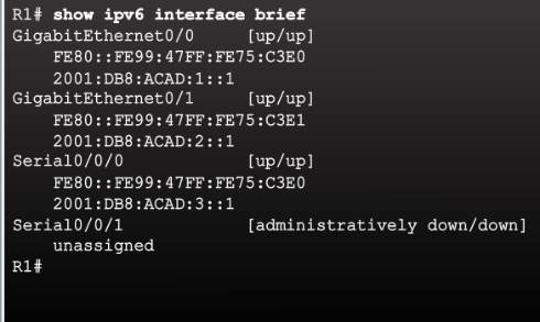
7.2.4.8 – Verifying IPv6 Address Configuration
The commands to verify IPv6 configuration are similar to IPv4
♦ show ipv6 interface brief
♦ show ipv6 route
The ping command for IPv6 is identical to the command used with IPv4, except that an IPv6 address is used.


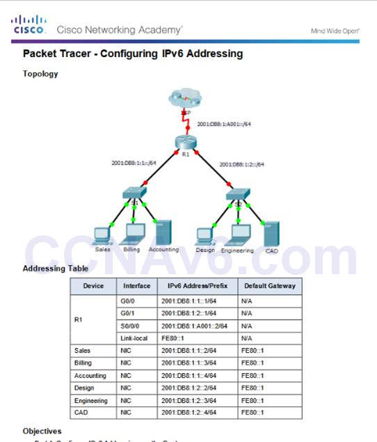
7.2.4.9 – Packet Tracer – Configuring IPv6 Addressing
7.2.4.9 Packet Tracer – Configuring IPv6 Addressing
7.2.5 – IPv6 Multicast Addresses
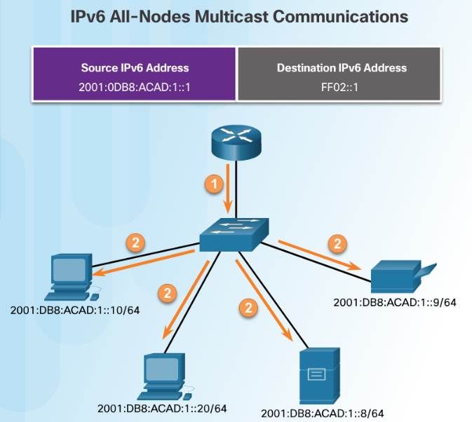
7.2.5.1 – Assigned IPv6 Multicast Addresses
There are two types of IPv6 multicast addresses:
♦ Assigned multicast – reserved multicast addresses for predefined groups of devices
♦ Solicited node multicast
Two common IPv6 assigned multicast groups:
♦ FF02::1 All-nodes multicast group – This is a multicast group that all IPv6-enabled devices join. Similar to a broadcast in IPv4
♦ FF02::2 All-routers multicast group – This is a multicast group that all IPv6 routers join.
7.2.5.2 – Solicited-Node IPv6 Multicast Addresses
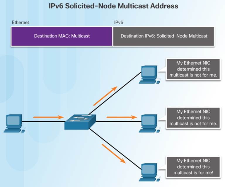
Solicited-node multicast address:
Mapped to .a special Ethernet multicast address
Allows Ethernet NIC to filter frame on destination MAC.
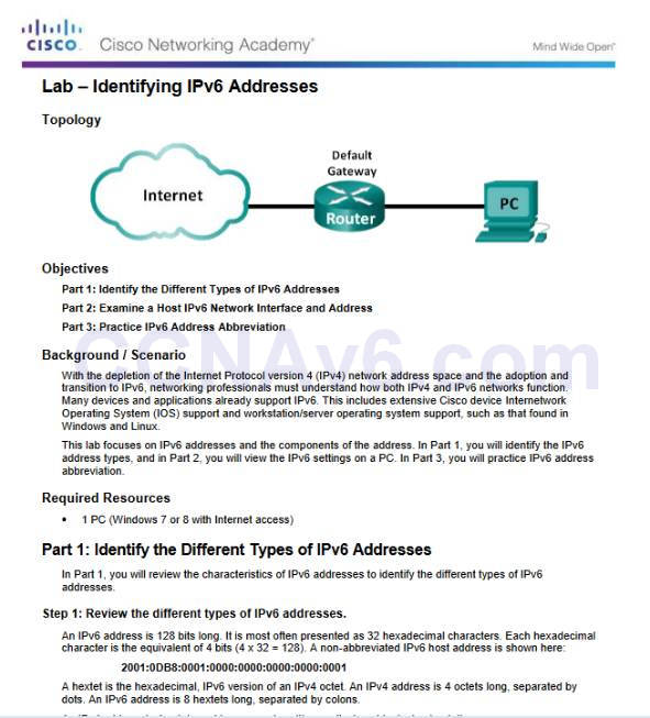
7.2.5.3 – Lab – Identifying IPv6 Addresses
7.2.5.3 Lab – Identifying IPv6 Addresses
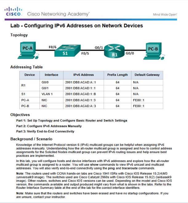
7.2.5.4- Lab – Configuring IPv6 Addresses on Network Devices
7.2.5.4 Lab – Configuring IPv6 Addresses on Network Devices
7.3 – Connectivity Verification
7.3.1 – ICMP
7.3.1.1 – ICMPv4 and ICMPv6
ICMPv4 is the messaging protocol for IPv4. ICMPv6 provides the same services for IPv6
ICMP messages common to both include:
♦ Host confirmation
♦ Destination or Service Unreachable
♦ Time exceeded
♦ Route redirection
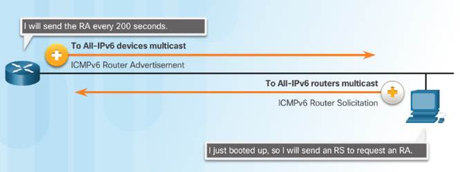
7.3.1.2 – ICMPv6 Router Solicitation and Router Advertisement Messages
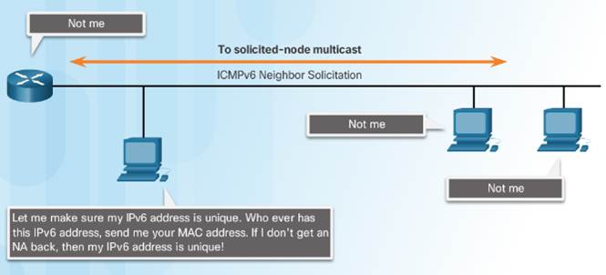
ICMPv6 includes four new protocols as part of the Neighbor Discovery Protocol (ND or NDP)
♦ Router Solicitation (RS) message
♦ Router Advertisement (RA) message
RA messages used to provide addressing information to hosts
♦ Neighbor Solicitation (NS) message
♦ Neighbor Advertisement (NA) message
Neighbor Solicitation and Neighbor Advertisement messages are used for Address resolution and Duplicate Address Detection (DAD).
7.3.2 – Testing and Verification
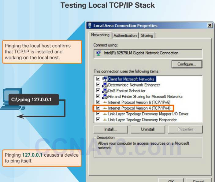
7.3.2.1 – Ping – Testing the Local Stack
Ping the local loopback address of 127.0.0.1 for IPv4 or ::1 for IPv6 to verify that IP is properly installed on the host.
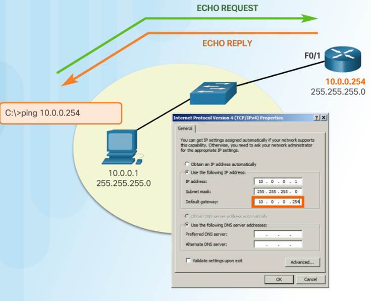
7.3.2.2 – Ping – Testing Connectivity to the Local LAN
Use ping to test the ability of a host to communicate on the local network.
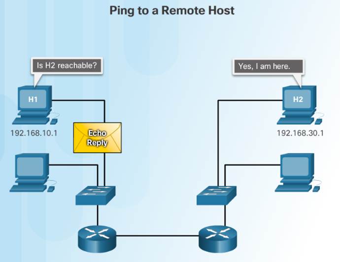
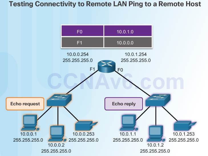
7.3.2.3 – Ping – Testing Connectivity to a Remote Host
Use ping to test the ability of a host to communicate across an internetwork.
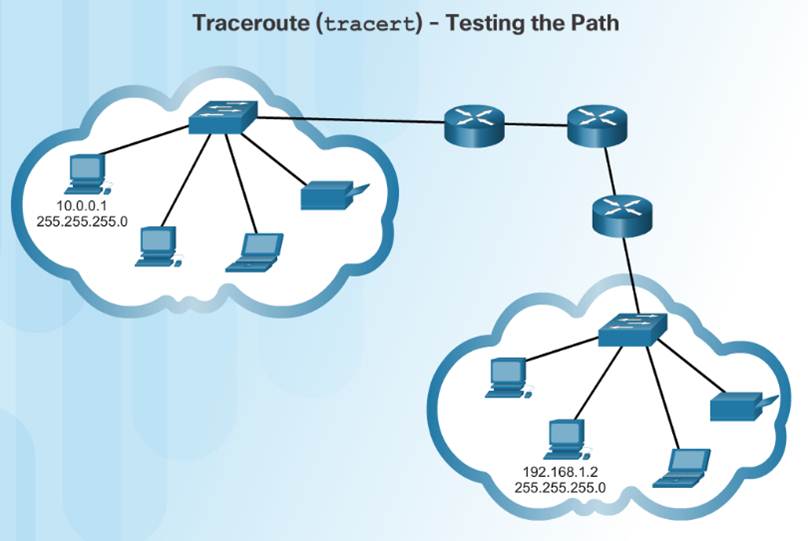
7.3.2.4 – Traceroute – Testing the Path
Traceroute (tracert) is a utility that generates a list of hops that were successfully reached along the path.
Round Trip Time (RTT) – Time it takes the packet to reach the remote host and for the response from the host to return.
Asterisk (*) is used to indicate a lost packet.
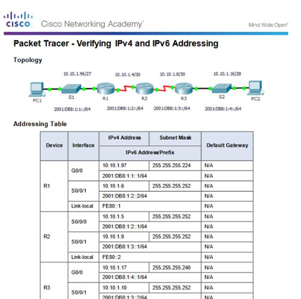
7.3.2.5 – Packet Tracer – Verifying IPv4 and IPv6 Addressing
7.3.2.5 Packet Tracer – Verifying IPv4 and IPv6 Addressing
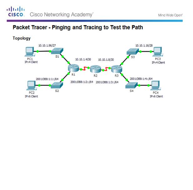
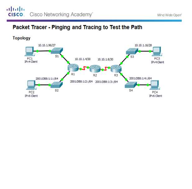
7.3.2.6 – Packet Tracer – Pinging and Tracing to Test the Path
7.3.2.6 Packet Tracer – Pinging and Tracing to Test the Path
7.3.2.7 – Lab – Testing Network Connectivity with Ping and Traceroute
7.3.2.7 Lab – Testing Network Connectivity with Ping and Traceroute
7.3.2.8 – Lab – Mapping the Internet
7.3.2.8 Lab – Mapping the Internet
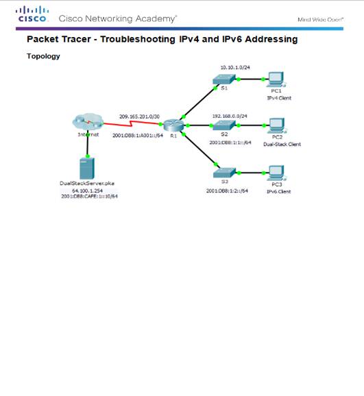
7.3.2.9 – Packet Tracer – Troubleshooting IPv4 and IPv6 Addressing
7.3.2.9 Packet Tracer – Troubleshooting IPv4 and IPv6 Addressing
7.4 – Summary
7.4.1 – Conclusion
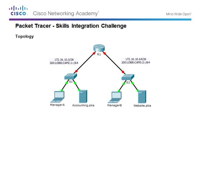
7.4.1.2 – Packet Tracer – Skills Integration Challenge
7.4.1.2 Packet Tracer – Skills Integration Challenge
7.4.1.3 – Chapter 7: IP Addressing
Explain the use of IPv4 addresses to provide connectivity in small to medium-sized business networks
Configure IPv6 addresses to provide connectivity in small to medium-sized business networks.
Use common testing utilities to verify and test network connectivity.
