Section 10 Tasks
- Read today’s lesson notes (below)
- Review yesterday’s lesson notes
- Complete today’s lab
- Read the ICND1 cram guide
- Spend 15 minutes on the subnetting.org website
The ICND1 exam requires you to have an understanding of basic routing and packet flow across a network. We will also take a look at the technology behind routing protocols.
Today you will learn about the following:
- Basic routing
- Classful and classless protocols
- Routing protocol classes
This module maps to the following CCNA syllabus requirements:
- Describe basic routing concepts
- CEF
- Packet forwarding
- Router lookup process
- Differentiate methods of routing and routing protocols
- Link State vs. Distance Vector
- Next hop
- IP routing table
- Passive interfaces (how they work)
Basic Routing
The role of routing protocols is to learn about other networks dynamically, exchange routing information with other devices, and connect internal and/or external networks.
It is important to note that routing protocols DO NOT send packets across the network. Their role is to determine the best path for routing. Routed protocols actually send the data, and the most common example of a routed protocol is IP.
Different routing protocols use different means of determining the best or most optimal path to a network or network node. Some types of routing protocols work best in static environments or environments with few or no changes, but it might take a long time to converge when changes to those environments are made. Other routing protocols, however, respond very quickly to changes in the network and can converge rapidly.
Network convergence occurs when all routers in the network have the same view and agree on optimal routes. When convergence takes a long time to occur, intermittent packet loss and loss of connectivity may be experienced between remote networks. In addition to these problems, slow convergence can result in network routing loops and outright network outages. Convergence is determined by the routing protocol algorithm used.
Because routing protocols have different characteristics, they differ in their scalability and performance. Some routing protocols are suitable only for small networks, while others may be used in small, medium, and large networks.
Packet Forwarding
Packet forwarding involves two processes:
- Determining the best path
- Sending the packet (switching)
When the router receives a packet for a directly connected network, the router checks the routing table and then the packet is forwarded to that network, as shown in Figure 10.1 below:
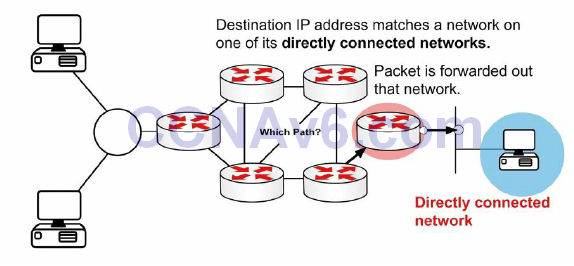
Figure 10.1 – Directly Connected Networks
If the packet is destined for a remote network, the routing table is checked and if there is a route or default route, the packet is forwarded to the next-hop router, as shown in Figure 10.2 below:
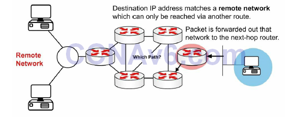
Figure 10.2 – Remote Networks
If the packet is destined for a network not in the routing table and no default route exists then it is dropped, as shown in Figure 10.3 below:
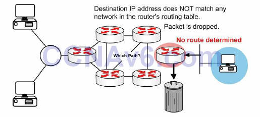
Figure 10.3 – No Route
The switching process allows the router to accept the packet via one interface and send it out of another. The router will also encapsulate the packet in the appropriate Data Link frame for the outgoing link.
You may be asked to explain what happens with a packet received from one network and destined for another network. Firstly, the router decapsulates the Layer 3 packet by removing the Layer 2 frame header and trailer. Next, it examines the destination IP address of the IP packet to find the best path in the routing table. Finally, it encapsulates the Layer 3 packet into a new Layer 2 frame and forwards the frame out of the exit interface, so the encapsulation could change from Ethernet to HDLC. This is illustrated in Figure 10.4 below:
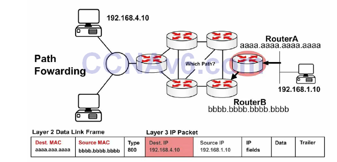
Figure 10.4 – Layer 3 Address in a Packet
Remember in an earlier module that the source and destination IP address will never change as the packet traverses towards its final destination. The MAC address, however, will change to permit transport between intermediary devices. This is illustrated in Figure 10.5 below:
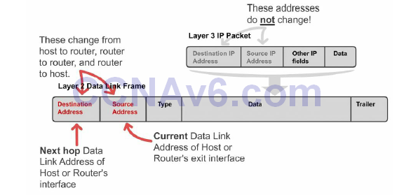
Figure 10.5 – Layer 2 Address Changes
Figure 10.6 shows a packet leaving Host X destined for Host Y. Note that the next-hop MAC address belongs to Router A (using proxy ARP); however, the IP address belongs to Host Y. When the frame reaches Router B, the Ethernet header and trailer will be exchanged for the WAN protocol, which you can presume is HDLC here.

Figure 10.6 – Packet Leaving Host X
Figure 10.7 shows the same packet leaving Router A for Router B. There is a route lookup and then the packet is switched out of interface E1. Type 800 indicates that the packet is IPv4.

Figure 10.7 – Packet Leaving Router A
Figure 10.8 shows that the frame eventually reaches Router C and is forwarded to Host Y:
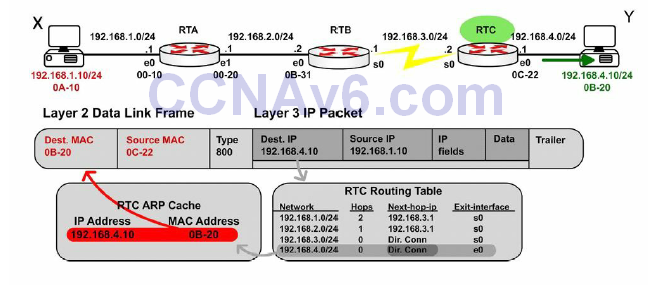
Figure 10.8 – Packet Leaving Router C
Internet Protocol Routing Fundamentals
A routing protocol allows a router to learn dynamically how to reach other networks. A routing protocol also allows the router to exchange learned network information with other routers or hosts. Routing protocols may be used for connecting interior (internal) campus networks, as well as for connecting different enterprises or routing domains. Therefore, in addition to understanding the intricacies of routing protocols, it is also important to have a solid understanding of when and in what situation one routing protocol would be used versus another.
Flat and Hierarchical Routing Algorithms
Routing protocol algorithms operate using either a flat routing system or a hierarchical routing system. A hierarchical routing system uses a layered approach wherein routers are placed in logical groupings referred to as domains, areas, or autonomous systems. This allows different routers within the network to perform specific tasks, optimising the functionality performed at those layers. Some routers in the hierarchical system can communicate with other routers in other domains or areas, while other routers can communicate only with routers in the same domain or area. This reduces the amount of information that routers in the domain or area must process, which allows for faster convergence within the network.
A flat routing system has no hierarchy. In such systems, routers must typically be connected to every other router in the network and each router essentially has the same function. Such algorithms work well in very small networks; however, they are not scalable. In addition, as the network grows, troubleshooting becomes much more difficult because instead of just focusing your efforts on certain areas, for example, you now have to look at the entire network.
The primary advantage afforded by hierarchical routing systems is their scalability. Hierarchical routing systems also allow for easier changes to the network, in much the same way afforded by the traditional hierarchical design comprised of the Core, Distribution, and Access Layers. In addition, hierarchical algorithms can be used to reduce routing update traffic, as well as routing table size, in certain areas of the network while still allowing full network connectivity.
IP Addressing and Address Summarisation
An IP address is divided into two parts. The first part designates the network address, while the second part designates the host address. When designing a network, an IP addressing scheme is used to uniquely identify hosts and devices within the network. The IP addressing scheme should be hierarchical and should build on the traditional logical hierarchical model. This allows the addressing scheme to provide designated points in the network where effective route summarisation can be performed.
Summarisation reduces the amount of information that routers must process, which allows for faster convergence within the network. Summarisation also restricts the size of the area that is affected by network changes by hiding detailed topology information from certain areas within the network. This concept is illustrated in Figure 10.9 below:
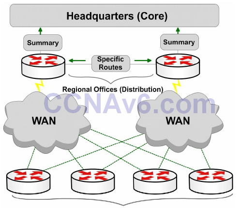
Figure 10.9 – Route Summarisation Using Cisco Design Model
Referencing Figure 10.9, the branch offices (Access Layer) are dual-homed to the regional office routers (Distribution Layer). Layers are defined using Cisco design models. Using a hierarchical addressing scheme allows the Distribution Layer routers to advertise a summary route for the branch office subnets to the Core Layer. This protects the Core Layer from the effects of any route flapping between the Distribution and the Access Layer routers, because a summary route will not flap until every last one of the more specific prefixes from which it is derived is removed from the routing table. This increases stability within the area. In addition, the routing table size at the Core Layer is further reduced.
Administrative Distance
Administrative distance is used to determine the reliability of one source of routing information from another. Some sources are considered more reliable than others are; therefore, administrative distance can be used to determine the best or preferred path to a destination network or network node when there are two or more different paths to the same destination from two or more different routing protocols.
In Cisco IOS software, all sources of routing information are assigned a default administrative distance value. This default value is an integer between 0 and 255, with a value of 0 assigned to the most reliable source of information and a value of 255 assigned to the least reliable source of information. Any routes that are assigned an administrative distance value of 255 are considered untrusted and will not be placed into the routing table.
The administrative distance is a locally significant value that affects only the local router. This value is not propagated throughout the routing domain. Therefore, manually adjusting the default administrative distance for a routing source or routing sources on a router affects the preference of routing information sources only on that router. Table 10.1 below shows the default administrative values used in Cisco IOS software (you need to learn these for the exam):
Table 10.1 – Router Administrative Distances (ADs)
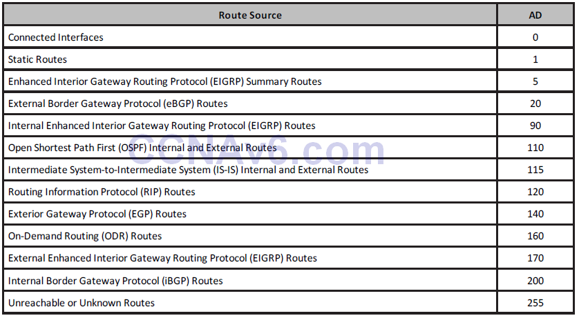
The default route source administrative distance is displayed in the output of the show ip protocols command. This is illustrated in the following output:
R1#show ip protocols
Routing Protocol is “isis”
Invalid after 0 seconds, hold down 0, flushed after 0
Outgoing update filter list for all interfaces is not set
Incoming update filter list for all interfaces is not set
Redistributing: isis
Address Summarization:
None
Maximum path: 4
Routing for Networks:
Serial0/0
Routing Information Sources:
Gateway         Distance      Last Update
10.0.0.2             115      00:06:53
Distance: (default is 115)
Routing Metrics
Routing protocol algorithms use metrics, which are numerical values that are associated with specific routes. These values are used to prioritise or prefer routes learned by the routing protocol, from the most preferred to the least preferred. In essence, the lower the route metric, the more preferred the route by the routing protocol. The route with the lowest metric is typically the route with the least cost or the best route to the destination network. This route will be placed into the routing table and will be used to forward packets to the destination network.
Different routing algorithms use different variables to compute the route metric. Some routing algorithms use only a single variable, while other advanced routing protocols may use more than one variable to determine the metric for a particular route. In most cases, the metrics that are computed by one routing protocol are incompatible with those used by other routing protocols. The different routing protocol metrics may be based on one or more of the following:
- Bandwidth
- Cost
- Delay
- Load
- Path length
- Reliability
Bandwidth
The term bandwidth refers to the amount of data that can be carried from one point to another in a given period. Routing algorithms may use bandwidth to determine which link type is preferred over another. For example, a routing algorithm might prefer a GigabitEthernet link to a FastEthernet link because of the increased capacity of the GigabitEthernet link over the FastEthernet link.
In Cisco IOS software, the bandwidth interface configuration command can be used to adjust the default bandwidth value for an interface, effectively manipulating the selection of one interface against another by a routing algorithm. For example, if the FastEthernet interface was configured with the bandwidth 1000000 interface configuration command, both the FastEthernet and the GigabitEthernet links would appear to have the same capacity to the routing algorithm and would be assigned the same metric value. The fact that one of the links is actually a FastEthernet link while the other is actually a GigabitEthernet link is irrelevant to the routing protocol.
From a network administrator’s point of view, it is important to understand that the bandwidth command does not affect the physical capability of the interface (so it is sometimes referred to as a cosmetic command). In other words, configuring the higher bandwidth on the FastEthernet interface does not mean that it is capable of supporting GigabitEthernet speeds. Open Shortest Path First (OSPF) and Enhanced Interior Gateway Routing Protocol (EIGRP) use bandwidth in metric calculations.
Cost
The cost, as it pertains to routing algorithms, refers to communication cost. The cost may be used when, for example, a company prefers to route across private links rather than public links that include monetary charges for sending data across them or for the usage time. Intermediate System-to-Intermediate System (IS-IS) supports an optional expense metric that measures the monetary cost of link utilisation. Configuring cost varies depending upon the protocol.
Delay
There are many types of delay, all of which affect different types of traffic. In general, delay refers to the length of time required to move a packet from its source to its destination through the internetwork. In Cisco IOS software, the interface delay value is in microseconds (μs).
The interface value is configured using the delay interface configuration command. When you configure the interface delay value, it is important to remember that this does not affect traffic (another cosmetic command). For example, configuring a delay value of 5000 does not mean that traffic sent out of that interface will have an additional delay of 5000 μs. Table 10.2 below shows the default delay values for common interfaces in Cisco IOS software:
Table 10.2 – Interface Delay Values
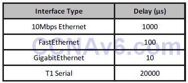
EIGRP uses the interface delay value as part of its metric calculation. Manually adjusting the interface delay value results in the re-computation of the EIGRP metric.
Load
The term load means different things to different people. For example, in general computing terminology, load refers to the amount of work a resource, such as the CPU, is performing. Load, as it applies in this context, refers to the degree of use for a particular router interface. The load on the interface is a fraction of 255. For example, a load of 255/255 indicates that the interface is completely saturated, while a load of 128/255 indicates that the interface is 50% saturated. By default, the load is calculated as an average over a period of five minutes (in the real world this is often changed to a minimum of 30 seconds using the load-interval 30 command). The interface load value can be used by EIGRP in its metric calculation.
Path Length
The path length metric is the total length of the path that is traversed from the local router to the destination network. Different routing algorithms represent this in different forms. For example, Routing Information Protocol (RIP) counts all intermediate routers (hops) between the local router and the destination network and uses the hop count as the metric, while Border Gateway Protocol (BGP) counts the number of traversed autonomous systems between the local router and the destination network and uses the autonomous system count to select the best path.
Reliability
Like load, the term reliability means different things depending upon the context in which it is used. Here, unless stated otherwise, it should always be assumed that reliability refers to the dependability of network links or interfaces. In Cisco IOS software, the reliability of a link or interface is represented as a fraction of 255. For example, a reliability value of 255/255 indicates that the interface is 100% reliable. Similar to the interface load, by default the reliability of an interface is calculated as an average over a period of five minutes.
Prefix Matching
Cisco routers use the longest prefix match rule when determining which of the routes placed into the routing table should be used to forward traffic to a destination network or node. Longer, or more specific, routing table entries are preferred over less specific entries, such as summary addresses, when determining which entry to use to route traffic to the intended destination network or node.
The longest prefix or the most specific route will be used to route traffic to the destination network or node, regardless of the administrative distance of the route source, or even the routing protocol metric assigned to the prefix if multiple overlapping prefixes are learned via the same routing protocol. Table 10.3 below illustrates the order of route selection on a router sending packets to the address 1.1.1.1. This order is based on the longest prefix match lookup:
Table 10.3 – Matching the Longest Prefix
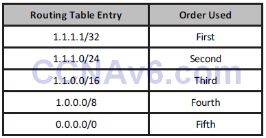
NOTE: Although the default route is listed last in the route selection order in Table 10.3, keep in mind that a default route is not always present in the routing table. If that is the case, and no other entries to the address 1.1.1.1 exist, packets to that destination are simply discarded by the router. In most cases, the router will send the source host an ICMP message indicting that the destination is unreachable. A default route is used to direct packets addressed to networks not explicitly listed in the routing table.
Building the IP Routing Table
Without a populated routing table, or Routing Information Base (RIB), that contains entries for remote networks, routers will not be able to forward packets to those remote networks. The routing table may include specific network entries or simply a single default route. The information in the routing table is used by the forwarding process to forward traffic to the destination network or host. The routing table itself does not actually forward traffic.
Cisco routers use the administrative distance, the routing protocol metric, and the prefix length to determine which routes will actually be placed into the routing table, which allows the router to build the routing table. The routing table is built via the following general steps:
1. If the route entry does not currently exist in the routing table, add it to the routing table.
2. If the route entry is more specific than an existing route, add it to the routing table. It
should also be noted that the less specific entry is still retained in the routing table.
3. If the route entry is the same as an existing one, but it is received from a more preferred
route source, replace the old entry with the new entry.
4. If the route entry is the same as an existing one, and it is received from the same
protocol, then:
i. Discard the new route if the metric is higher than the existing route; or
ii. Replace the existing route if the metric of the new route is lower; or
iii. Use both routes for load balancing if the metric for both routes is the same.
When building the RIB by default, the routing protocol with the lowest administrative distance value will always be chosen when the router is determining which routes to place into the routing table. For example, if a router receives the 10.0.0.0/8 prefix via external EIGRP, OSPF, and internal BGP, the OSPF route will be placed into the routing table. If that route is removed or is no longer received, the external EIGRP route will be placed into the routing table. Finally, if both the OSPF and the external EIGRP routes are no longer present, the internal BGP route is used.
Once routes have been placed into the routing table, by default the most specific or longest match prefix will always be preferred over less specific routes. This is illustrated in the following example, which shows a routing table that contains entries for the 80.0.0.0/8, 80.1.0.0/16, and 80.1.1.0/24 prefixes. These three route prefixes are received via the EIGRP, OSPF, and RIP routing protocols, respectively.
R1#show ip route
Codes: C - connected, S - static, R - RIP, M - mobile, B - BGP
D - EIGRP, EX - EIGRP external, O - OSPF, IA - OSPF inter area
N1 - OSPF NSSA external type 1, N2 - OSPF NSSA external type 2
E1 - OSPF external type 1, E2 - OSPF external type 2
i - IS-IS, L1 - IS-IS level-1, L2 - IS-IS level-2, ia - IS-IS inter area
* - candidate default, U - per-user static route, o - ODR
P - periodic downloaded static route
Gateway of last resort is not set
R       80.1.1.0/24 [120/1] via 10.1.1.2, 00:00:04, Ethernet0/0.1
D       80.0.0.0/8 [90/281600] via 10.1.1.2, 00:02:02, Ethernet0/0.1
O E2    80.1.0.0/16 [110/20] via 10.1.1.2, 00:00:14, Ethernet0/0.1
Referencing the output shown above, the first route is 80.1.1.0/24. This route is learned via RIP and therefore has a default administrative distance value of 120. The second route is 80.0.0.0/8. This route is learned via internal EIGRP and therefore has a default administrative distance value of 90. The third route is 80.1.0.0/16. This route is learned via OSPF and is an external OSPF route that has an administrative distance of 110.
NOTE: Because the routing protocol metrics are different, they are a non-factor in determining the best route to use when routes from multiple protocols are installed into the routing table. The following section will describe how Cisco IOS routers build the routing table.
Based on the contents of this routing table, if the router received a packet destined to 80.1.1.1, it would use the RIP route because this is the most specific entry, even though both EIGRP and OSPF have better administrative distance values and are therefore more preferred route sources. The show ip route 80.1.1.1 command illustrated below can be used to verify this statement:
R1#show ip route 80.1.1.1
Routing entry for 80.1.1.0/24
Known via “rip”, distance 120, metric 1
Redistributing via rip
Last update from 10.1.1.2 on Ethernet0/0.1, 00:00:15 ago
Routing Descriptor Blocks:
* 10.1.1.2, from 10.1.1.2, 00:00:15 ago, via Ethernet0/0.1
Route metric is 1, traffic share count is 1
Classful and Classless Protocols
Classful protocols can’t use VLSM (i.e., RIPv1 and IGRP, which are no longer in the CCNA syllabus). This is because they don’t recognise anything other than default network masks:
Router#debug ip rip
RIP protocol debugging is on
01:26:59: RIP: sending v1 update to 255.255.255.255 via Loopback0
192.168.1.1
Classless protocols use VLSM (i.e., RIPv2 and EIGRP):
Router#debug ip rip
RIP protocol debugging is on
01:29:15: RIP: received v2 update from 172.16.1.2 on Serial0
01:29:15:192.168.2.0/24 via 0.0.0.0
Passive Interfaces
An important routing protocol design and configuration consideration is to limit unnecessary peerings, as shown in Figure 10.10 below. This is done using passive interfaces, which prevents the router from forming routing adjacencies on the specific interface. This functions differently based on the specific routing protocol used but the behaviour usually falls within the following two categories:
- The router does not send routing updates on the passive interface
- The router does not send Hello packets on the interface, so neighbour relationships are
not formed
Passive interfaces are usually able to receive routing updates or Hello packets but are not allowed to send any kind of routing protocol information outbound.
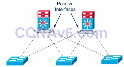
Figure 10.10 – Limit Unnecessary Peerings
A use case example for passive interfaces is avoiding routing protocol peerings from the Distribution Layer to the Access Layer, as presented in Figure 10.10 above. By having Layer 3 peering across the different Access Layer switches (i.e., having multiple hosts on different switches across switch blocks) you are basically adding memory load, routing protocol update overhead, and more complexity. Also, if there is a link failure, the traffic may transit through a neighbouring Access Layer switch to get to another VLAN member.
Basically, you want to eliminate unnecessary routing peering adjacencies, so you would configure the ports towards the Layer 2 switches as passive interfaces in order to suppress routing updates advertisements. If a Distribution Layer switch does not receive a routing update from a potential peer on one of these interfaces, it will not have to process the updates and will not form a neighbour adjacency across that interface. The command for accomplishing this is usually passive-interface [interface number] in the Routing Process Configuration mode. Please read a CCDA guide for more information on the Cisco design model.
Routing Protocol Classes
There are two major classes of routing protocols – Distance Vector and Link State. Distance Vector routing protocols traditionally use a one-dimensional vector when determining the most optimal path(s) through the network, while Link State routing protocols use the Shortest Path First (SPF) when determining the most optimal path(s) through the network. Before delving into the specifics of these two classes of routing protocols, we will first take a look at vectors, as well as at the elusive SPF algorithm.
Understanding Vectors
A one-dimensional vector is a directed quantity. It is simply a quantity (number) in a particular direction or course. The vector concept is illustrated in Figure 10.11 below:

Figure 10.11 – Understanding Vectors
Referencing Figure 10.11, the first line starts at 0 and ends at 8, and the second line begins at 8 and ends at 13. The vector for the first line is 8, while the vector for the second line is 5. Using basic math, we know that 8 + 5 = 13. The starting and ending points of the vector are not relevant. Instead, the only thing that actually matters is how long the vector is and how far it travels.
NOTE: Vectors can also travel in the opposite direction (i.e., they represent negative numbers).
The Shortest Path First Algorithm
The SPF algorithm creates a shortest-path tree to all hosts in an area or in the network backbone with the router that is performing the calculation at the root of that tree. In order for the SPF algorithm to work in the correct manner, all routers in the area should have the same database information. In OSPF, this is performed via the database exchange process.
Distance Vector Routing Protocols
Distance Vector is a routing protocol that uses distance or hop count as its primary metric for determining the best forwarding path. Distance Vector routing protocols are primarily based on the Bellman-Ford algorithm. Distance Vector routing protocols periodically send their neighbour routers copies of their entire routing tables to keep them up to date on the state of the network. While this may be acceptable in a small network, it increases the amount of traffic that is sent across networks as the size of the network grows. All Distance Vector routing protocols share the following characteristics:
- Counting to infinity
- Split horizon
- Poison reverse
- Hold-down timers
Utilising the counting to infinity characteristic, if a destination network is farther than the maximum number of hops allowed for that routing protocol, the network would be considered unreachable. The network entry would therefore not be installed into the IP routing table.
Split horizon mandates that routing information cannot be sent back out of the same interface through which it was received. This prevents the re-advertising of information back to the source from which it was learned. While this characteristic is a great loop prevention mechanism, it is also a significant drawback, especially in hub-and-spoke networks.
Poison reverse (or route poisoning) expands on split horizon. When used in conjunction with split horizon, poison reverse allows the networks to be advertised back out of the same interface on which they were received. However, poison reverse causes the router to advertise these networks back to the sending router with a metric of “unreachable” so that the router that receives those entries will not add them back into its routing table.
Hold-down timers are used to prevent networks that were previously advertised as down from being placed back into the routing table. When a router receives an update that a network is down, it begins its hold-down timer. This timer tells the router to wait for a specific amount of time before accepting any changes to the status of that network.
During the hold-down period, the router suppresses the network and prevents advertising false information. The router also does not route to the unreachable network, even if it receives information from another router (that may not have received the triggered update) that the network is reachable. This mechanism is designed to prevent black-holing traffic.
The two most common Distance Vector routing protocols are RIP and IGRP. EIGRP is an advanced Distance Vector routing protocol, using features from both Distance Vector and Link State (i.e., it’s a hybrid protocol).
Link State Routing Protocols
Link State routing protocols are hierarchical routing protocols that use the concept of areas to logically group routers within a network. This allows Link State protocols to scale better and operate in a more efficient manner than Distance Vector routing protocols. Routers running Link State routing protocols create a database that comprises the complete topology of the network. This allows all routers within the same area to have the same view of the network.
Because all routers in the network have the same view of the network, the most optimal paths are used for forwarding packets between networks and the possibility of routing loops is eliminated. Therefore, techniques such as split horizon and route poisoning do not apply to Link State routing protocols as they do to Distance Vector routing protocols.
Link State routing protocols operate by sending Link State Advertisements or Link State Packets to all other routers within the same area. These packets include information on attached interfaces, metrics, and other variables. As the routers accumulate this information, they run the SPF algorithm and calculate the shortest (best) path to each router and destination network. Using the received Link State information, routers build the Link State Database (LSDB). When the LSDBs of two neighbouring routers are synchronised, the routers are said to be adjacent.
Unlike Distance Vector routing protocols, which send their neighbours their entire routing table, Link State routing protocols send incremental updates when a change in the network topology is detected, which makes them more efficient in larger networks. The use of incremental updates also allows Link State routing protocols to respond much faster to network changes and thus converge in a shorter amount of time than Distance Vector routing protocols. Table 10.4 below lists the different Interior Gateway Protocols (IGPs) and their classification:
Table 10.4 – IGP Classification

The Objectives of Routing Protocols
Routing algorithms, while different in nature, all have the same basic objectives. While some algorithms are better than others are, all routing protocols have their advantages and disadvantages. Routing algorithms are designed with the following objectives and goals:
- Optimal routing
- Stability
- Ease of use
- Flexibility
- Rapid convergence
Optimal Routing
One of the primary goals of all routing protocols is to select the most optimal path through the network from the source subnet or host to the destination subnet or host. The most optimal route depends upon the metrics used by the routing protocols. A route that may be considered the best by one protocol may not necessarily be the most optimal route from the perspective of another protocol. For example, RIP might consider a path that is only two hops long as the most optimal path to a destination network, even though the links were 64Kbps links, while advanced protocols such as OSPF and EIGRP might determine that the most optimal path to that same destination is the one traversing four routers but using 10Gbps links.
Stability
Network stability, or a lack thereof, is another major objective for routing algorithms. Routing algorithms should be stable enough to accommodate unforeseen network events, such as hardware failures and even incorrect implementations. While this is typically a characteristic of all routing algorithms, the manner and time in which they respond to such events makes some better than others and thus more preferred in modern-day networks.
Ease of Use
Routing algorithms are designed to be as simple as possible. In addition to providing the capability to support complex internetwork deployments, routing protocols should take into consideration the resources required to run the algorithm. Some routing algorithms require more hardware or software resources (e.g., CPU and memory) to run than others do; however, they are capable of providing more functionality than alternative simple algorithms.
Flexibility
In addition to providing routing functionality, routing algorithms should also be feature-rich, allowing them to support the different requirements encountered in different networks. It should be noted that this capability typically comes at the expense of other features, such as convergence, which is described next.
Rapid Convergence
Rapid convergence is another primary objective of all routing algorithms. As stated earlier, convergence occurs when all routers in the network have the same view of and agree on optimal routes. When convergence takes a long time to occur, intermittent packet loss and loss of connectivity may be experienced between remote networks. In addition to these problems, slow convergence can result in network routing loops and outright network outages.
Routing Problems Avoidance Mechanisms
It is a known fact that Distance Vector routing protocols are prone to major problems as a result of their simplistic “routing by rumor” approach. Distance Vector and Link State protocols use different techniques to prevent routing problems. The most important mechanisms include the following:
- Invalidation timers: These are used to mark routes as unreachable when updates for those routes are not received for a long time.
- Hop count limit: This parameter marks routes as unreachable when they are more than a predefined number of hops away. The hop count limit for RIP is 15, as it is not usually used in large networks. Unreachable routes are not installed in the routing table as best routes. The hop count limit prevents updates from looping in the network, just like the TTL field in the IP header.
- Triggered updates: This feature allows the update timer to be bypassed in the case of important updates. For example, the RIP 30-second timer can be ignored if a critical routing update must be propagated through the network.
- Hold-down timers: If a metric for a particular route keeps getting worse, updates for that route are not accepted for a delayed period.
- Asynchronous updates: Asynchronous updates represent another safety mechanism that prevents the routers from flooding the entire routing information at the same time. As mentioned before, OSPF does this every 30 minutes. The asynchronous updates mechanism generates a small delay for every device so they do not flood the information exactly at the same time. This improves bandwidth utilisation and processing capabilities.
- Route poisoning: This feature prevents routers from sending packets through a route that has become invalid. Distance Vector protocols use this to indicate that a route is no longer reachable. This is accomplished by setting the route metric to a maximum value.
- Split horizon: Split horizon prevents updates from being sent out of the same interface they came from because routers in that area should already know about that specific update.
- Poison reverse: This mechanism is an exception to the split horizon rule for the poisoned routes.
Topology-Based (CEF) Switching
Matching a packet’s intended destination address with the IP routing table requires router CPU cycles. Enterprise routers can contain tens of thousands of entries and can match the same number of incoming packets against these entries. In an attempt to make this process as efficient as possible, Cisco has created various switching methods. The first is called process switching and it uses the route lookup and best match method already outlined. This method was improved upon with fast switching. A list of IP addresses of recently forwarded packets is generated by the router as well as the Data Link Layer headers that were copied if the IP address matched. Cisco Express Forwarding (CEF) was created as an improvement on fast switching. CEF runs on current models of Cisco routers by default.
Cisco Express Forwarding (CEF)
CEF operates at the data plane and is a topology-driven proprietary switching mechanism that creates a forwarding table that is tied to the routing table (i.e., the control plane). CEF was developed to eliminate the performance penalty experienced due to the first-packet processswitched lookup method used by flow-based switching. CEF eliminates this by allowing the route cache used by the hardware-based Layer 3 routing engine to contain all the necessary information to the Layer 3 switch in the hardware before any packets associated with a flow are even received. Information that is conventionally stored in a route cache is stored in two data structures for CEF switching. These data structures provide optimised lookup for efficient packet forwarding and are referred to as the FIB and the adjacency table.
NOTE: It is important to remember that even with CEF, whenever there are routing table changes, the CEF forwarding table is also updated. While new CEF entries are being created, packets are switched in a slower switching path, using process switching, for example. All current models of Cisco routers and current IOS use CEF.
Forwarding Information Base (FIB)
CEF uses a FIB to make IP destination prefix-based switching decisions. The FIB is conceptually similar to a routing table or information base. It maintains a mirror image of the forwarding information contained in the IP routing table. In other words, the FIB contains all IP prefixes from the routing table.
When routing or topology changes occur in the network, the IP routing table is updated, and those changes are also reflected in the FIB. The FIB maintains next-hop address information based on the information in the IP routing table. Because there is a one-to-one correlation between FIB entries and routing table entries, the FIB contains all known routes and eliminates the need for route cache maintenance that is associated with switching paths, such as fast switching and optimum switching.
Additionally, because the FIB lookup table contains all known routes that exist in the routing table, it eliminates route cache maintenance and the fast-switching and process-switching forwarding scenarios. This allows CEF to switch traffic more efficiently than typical demandcaching schemes.
The Adjacency Table
The adjacency table was created to contain all connected next hops. An adjacent node is a node that is one hop away (i.e., directly connected). The adjacency table is populated as adjacencies are discovered. As soon as a neighbour becomes adjacent, a Data Link Layer header, called a MAC string or a MAC rewrite, which will be used to reach that neighbour, is created and stored in the table. On Ethernet segments, this header information is the destination MAC address, the source MAC address, and the EtherType, in that specific order.
As soon as a route is resolved, it points to an adjacent next hop. If an adjacency is found in the adjacency table, a pointer to the appropriate adjacency is cached in the FIB element. If multiple paths exist for the same destination, a pointer to each adjacency is added to the load-sharing structure, which allows for load balancing. When prefixes are added to the FIB, prefixes that require exception handling are cached with special adjacencies.
Accelerated and Distributed CEF
By default, all CEF-based Cisco Catalyst switches use a central Layer 3 switching engine where a single processor makes all Layer 3 switching decisions for traffic received on all ports in the switch. Even though the Layer 3 switching engines used in Cisco Catalyst switches provide high performance, in some networks, having a single Layer 3 switching engine do all the Layer 3 switching does not provide sufficient performance. To address this issue, Cisco Catalyst 6500 series switches allow for CEF optimisation through the use of specialised forwarding hardware. This is performed using either Accelerated CEF (aCEF) or Distributed CEF (dCEF).
Accelerated CEF allows a portion of the FIB to be distributed to capable line card modules in the Catalyst 6500 switch. This allows the forwarding decision to be made on the local line card using the locally stored scaled-down CEF table. In the event that FIB entries are not found in the cache, requests are sent to the Layer 3 engine for more FIB information.
Distributed CEF refers to the use of multiple CEF tables distributed across multiple line cards installed in the chassis. When using dCEF, the Layer 3 engine (MSFC) maintains the routing table and generates the FIB, which is then dynamically downloaded in full to each of the line cards, allowing for multiple Layer 3 data plane operations to be performed simultaneously.
In summation, dCEF and aCEF are technologies that implement multiple Layer 3 switching engines so that simultaneous Layer 3 switching operations can occur in parallel, boosting overall system performance. CEF technology offers the following benefits:
- Improved performance – CEF is less CPU-intensive than fast-switching route caching. More CPU processing power can be dedicated to Layer 3 services, such as Quality of Service (QoS) and encryption, for example.
- Scalability – CEF offers full switching capacity at each line card in high-end platforms, such as the Catalyst 6500 series switches, when dCEF mode is active.
- Resilience – CEF offers an unprecedented level of switching consistency and stability in large dynamic networks. In dynamic networks, fast-switching cache entries are frequently invalidated due to routing changes. These changes can cause traffic to be processswitched using the routing table rather than fast-switched using the route cache.
Configuring Cisco Express Forwarding
Enabling CEF requires the use of a single command, which is the ip cef [distributed] global configuration command. The [distributed] keyword is only applicable to high-end switches, such as the Catalyst 6500 series switches, that support dCEF. The following output shows how to configure CEF on a lower-end platform, such as the Catalyst 3750 series switch:
VTP-Server-1(config)#ip cef
VTP-Server-1(config)#exit
The following output illustrates how to enable dCEF on the Catalyst 6500 series switches:
VTP-Server-1(config)#ip cef distributed
VTP-Server-1(config)#exit
NOTE: There is no explicit command to configure or enable aCEF.
Troubleshooting Routing Issues
When configuring routing on your network devices, you have to carefully configure static or dynamic routing based on the design. If you have a problem and are not able to send/receive traffic across the network, then you probably have some kind of configuration issue. When you initially set up a router there will most likely be some type of configuration problem that you will have to troubleshoot. If the router has been running for a while and you suddenly have a complete failure of traffic (no communication), you should analyse the situation and figure out whether the routing protocol functions as expected.
Sometimes certain routes might intermittently disappear and appear from the routing table, causing intermittent connectivity to specific destinations. This may be because a certain network area has some kind of communication problem and routers along the path propagate new routing information every time that area becomes accessible. This process is called “route flapping,” and the specific routes can be blocked so the entire network is not affected using a feature called “route dampening.”
NOTE: When using static routing, the routing table never changes so you will have no idea about problems that occur in different network areas.
When troubleshooting routing issues the standard approach is to follow the routing table for every route along the path. You might perform a traceroute to find out exactly where the packets are going and to see the routers along the path. This way you would know exactly which device might be causing the issues and you can start investigating the routing tables of the specific routers.
A common mistake when performing such a troubleshooting process is investigating the issue in a single direction (for example, source to destination). Instead, you should perform the troubleshooting in both directions because you might come across situations in which packets are blocked in a single direction and you have no return traffic from the destination to the source. The routing tables on devices along the path between two points should correctly point in both directions in order to ensure an optimal traffic flow.
Often you will be using connections provided by third parties, so when you want to troubleshoot issues in a certain area you should communicate with the provider and synchronise the troubleshooting effort. This includes sharing routing table information.
Using dynamic routing protocols makes the troubleshooting process easier because you can inspect the routing updates as they are sent and received by the router. This can be done via packet capture or internal device mechanisms and will help you to see how and when the routing table is populated. Having a topology map and other documentation that lists where every prefix is located in the network would further help your understanding of the routing updates and would shorten the troubleshooting process. The general idea in such a troubleshooting process is deciding which path a specific packet should take, based on the network design, and investigating where exactly it is deviating from this path.
Different tools can be used to monitor network devices. A common network management protocol used by these tools is Simple Network Management Protocol (SNMP), which was designed to query network devices for different parameters from a management station (SNMP is covered in ICND2). Besides the standard “health” parameters checked (e.g., CPU, memory, disk space, etc.), SNMP can also query the router for things like:
- Interface packet counters
- Used bandwidth and throughput
- CRC or other types of errors on device interfaces
- Routing table information
Other types of tools you can use are standard ping and traceroute utilities in order to verify end-to-end connectivity. They can also show relevant output that might help you determine the point in the network where problems occur.
The steps to troubleshooting almost all routing issues include the following:
- Verifying that routing is enabled
- Verifying that the routing table is valid
- Verifying the correct path selection
Verifying That Routing Is Enabled
The first step in troubleshooting routing is verifying that the routing protocol is enabled and properly configured. This can be done either by inspecting the current running configuration (i.e., the show run command) or by using show commands associated with each particular routing protocol. Some of these options are listed below:
Router#show ip ospf ?
<1-65535>            Process ID number
border-routers       Border and boundary router information
database             Database summary
flood-list            Link state flood list
interface            Interface information
max-metric           Max-metric origination information
mpls                 MPLS related information
neighbor             Neighbor list
request-list         Link state request list
retransmission-list  Link state retransmission list
rib                  Routing information base (RIB)
sham-links           Sham link information
statistics           Various OSPF Statistics
summary-address      Summary-address redistribution information
timers               OSPF timers information
traffic               Traffic related statistics
virtual-links        Virtual link information
|                    Output modifiers
<cr>
Router#show ip eigrp ?
<1-65535>   Autonomous System
accounting  IP-EIGRP accounting
interfaces  IP-EIGRP interfaces
neighbors   IP-EIGRP neighbors
topology    IP-EIGRP topology table
traffic      IP-EIGRP traffic statistics
vrf         Select a VPN routing/forwarding instance
Router#show ip bgp ?
A.B.C.D            Network in the BGP routing table to display
A.B.C.D/nn         IP prefix <network>/<length>, e.g., 35.0.0.0/8
all                All address families
cidr-only          Display only routes with non-natural netmasks
community          Display routes matching the communities
community-list     Display routes matching the community-list
dampening          Display detailed information about dampening
extcommunity-list  Display routes matching the extcommunity-list
filter-list         Display routes conforming to the filter-list
inconsistent-as    Display only routes with inconsistent origin ASs
injected-paths     Display all injected paths
ipv4               Address family
ipv6               Address family
labels             Display labels for IPv4 NLRI specific information
neighbors          Detailed information on TCP and BGP neighbor connections
nsap               Address family
oer-paths          Display all oer controlled paths
paths              Path information
peer-group         Display information on peer-groups
pending-prefixes    Display prefixes pending deletion
prefix-list         Display routes matching the prefix-list
quote-regexp       Display routes matching the AS path “regular expression”
regexp             Display routes matching the AS path regular expression
replication        Display replication status of update-group(s)
rib-failure        Display bgp routes that failed to install in the routing table (RIB)
route-map          Display routes matching the route-map
summary            Summary of BGP neighbor status
template           Display peer-policy/peer-session templates
update-group       Display information on update-groups
vpnv4              Address family
|                  Output modifiers
<cr>
Verifying That the Routing Table Is Valid
After successfully determining that the routing process is enabled, the next step is to analyse the routing table and see whether the information listed there is valid. Some of the points you should focus on include:
- Verifying that the correct prefixes are being learned via the correct routing protocol
- Verifying the number of learned prefixes
- Verifying route metrics and next-hop information
Depending on the routing protocol, you should also verify that the correct prefixes are being advertised outbound from your device.
Verifying the Correct Path Selection
After verifying that the relevant prefixes are indeed present in the routing table, you should carefully analyse their attributes and the path selection method for each of them. This might include:
- Verifying all the routing protocols that advertise that specific prefix (including static
routing) - Comparing and manipulating the AD in order to prefer it over the correct routing protocol
- Verifying and adjusting protocol metrics
By properly configuring the router in your network, documenting each step along the way, and constantly monitoring the path between different points in the network, you will have a solid understanding of exactly how the traffic should traverse all the devices in the network.
Section 10 Questions
1. What is a routing protocol?
2. _______ is used to determine the reliability of one source of routing information from another.
3. If a router learns a route from both EIGRP (internal) and OSPF, which one would it prefer?
4. What is the RIP AD?
5. What is the eBGP AD?
6. Name at least four routing metrics.
7. Once routes have been placed into the routing table, by default the most specific or longest match prefix will always be preferred over less specific routes. True or false?
8. _______ operates at the data plane and is a topology-driven proprietary switching mechanism that creates a forwarding table that is tied to the routing table (i.e., the control plane).
9. CEF uses a _______ to make IP destination prefix-based switching decisions.
10. Link State routing protocols are those that use distance or hop count as its primary metric for determining the best forwarding path. True or false?
Section 10 Answers
1. A protocol that allows a router to learn dynamically how to reach other networks.
2. Administrative distance.
3. EIGRP.
4. 120.
5. 20.
6. Bandwidth, cost, delay, load, reliability, and hop count.
7. True.
8. CEF.
9. FIB.
10. False.
Section 10 Lab
Routing Concepts Lab
Use two directly connected routers and test the basic commands depicted in this module. RIP is no longer in the CCNA exam but it’s a very easy protocol to use for a simple lab.
- Assign an IPv4 address to the directy connected interfaces (10.10.10.1/24 and 10.10.10.2/24)
- Test direct connectivity using ping
- Configure a Loopback interface on each router and assign addresses from two different ranges (11.11.11.1/32 and 12.12.12.2/32)
- Configure standard RIP and advertise all the local networks
R1:
router rip
version 2
no auto
network 10.10.10.0
network 11.11.11.0
R2:
router rip
version 2
no auto
network 10.10.10.0
network 12.12.12.0
- Ping R2 Loopback from R1 to test connectivity
- Issue a show ip route command to verify that routes are being received via RIP
- Issue a show ip protocols command to verify that RIP is configured and active on the devices
