Section 34 Tasks
- Read today’s lesson notes (below)
- Review yesterday’s lesson notes
- Complete today’s lab
- Read the ICND2 cram guide
- Spend 15 minutes on the subnetting.org website
High Availability (HA) is an integral component when designing and implementing switched networks. HA is technology delivered in Cisco IOS software that enables networkwide resilience to increase IP network availability. All network segments must be resilient to recover quickly enough for faults to be transparent to users and network applications. First Hop Redundancy Protocols (FHRPs) provide redundancy in switched LAN environments.
Today you will learn about the following:
- Hot Standby Router Protocol
- Virtual Router Redundancy Protocol
- Gateway Load Balancing Protocol
This lesson maps to the following ICND2 syllabus requirements:
- Recognise High Availability (FHRP)
- HSRP
- VRRP
- GLBP
Hot Standby Router Protocol
Hot Standby Router Protocol (HSRP) is a Cisco-proprietary First Hop Redundancy Protocol (FHRP). HSRP allows two physical gateways that are configured as part of the same HSRP group to share the same virtual gateway address. Network hosts residing on the same subnet as the gateways are configured with the virtual gateway IP address as their default gateway.
While operational, the primary gateway forwards packets destined to the virtual gateway IP address of the HSRP group. In the event that the primary gateway fails, the secondary gateway assumes the role of primary gateway and forwards all packets sent to the virtual gateway IP address. Figure 34.1 below illustrates the operation of HSRP in a network:
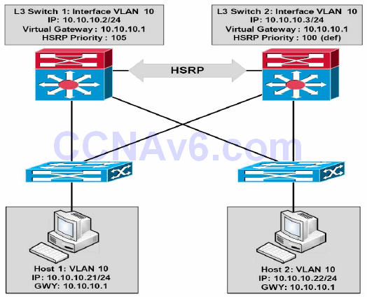
Figure 34.1 – Hot Standby Router Protocol (HSRP) Operation
Referencing Figure 34.1, HSRP is configured between the Layer 3 (Distribution Layer) switches,providing gateway redundancy for VLAN 10. The IP address assigned to the Switch Virtual Interface (SVI) on Layer 3 Switch 1 is 10.10.10.2/24, and the IP address assigned to the SVI on Layer 3 Switch 2 is 10.10.10.3/24. Both switches are configured as part of the same HSRP group and share the IP address of the virtual gateway, which is 10.10.10.1.
Switch 1 has been configured with a priority of 105, while Switch 2 is using the default priority of 100. Because of the higher priority, Layer 3 Switch 1 is elected as the primary switch and Layer 3 Switch 2 is elected as the secondary switch. All hosts on VLAN 10 are configured with a default gateway address of 10.10.10.1. Based on this solution, Switch 1 will forward all packets sent to the 10.10.10.1 address. However, in the event that Switch 1 fails, then Switch 2 will assume this responsibility. This process is entirely transparent to the network hosts.
Real-World Implementation
In production networks, when configuring FHRPs, it is considered good practice to ensure that the active (primary) gateway is also the Spanning Tree Root Bridge for the particular VLAN. Referencing the diagram in Figure 34.1, for example, Switch 1 would be configured as the Root Bridge for VLAN 10 in tandem with being the HSRP primary gateway for the same VLAN.
This results in a deterministic network and avoids suboptimal forwarding at Layer 2 or Layer 3. For example, if Switch 2 was the Root Bridge for VLAN 10, while Switch 1 was the primary gateway for VLAN 10, packets from the network hosts to the default gateway IP address would be forwarded as shown in Figure 34.2 below:
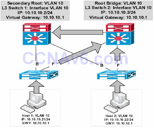
Figure 34.2 – Synchronising the STP Topology with HSRP
In the network above, packets from Host 1 to 10.10.10.1 are forwarded as follows:
- The Access Layer switch receives a frame destined to the MAC address of the virtual gateway IP address from Host 1. This frame is received in VLAN 10 and the MAC address for the virtual gateway has been learned by the switch via its Root Port.
- Because the Root Bridge for VLAN 10 is Switch 2, the uplink towards Switch 1 (the HSRP primary router) is placed into a Blocking state. The Access Layer switch forwards the frame via the uplink to Switch 2.
- Switch 2 forwards the frame via the Designated Port connected to Switch 1. The same suboptimal forwarding path is used for frames received from Host 2.
Currently, two versions of HSRP are supported in Cisco IOS software: versions 1 and 2. The similarities and differences between the versions will be described in the sections that follow.
HSRP Version 1
By default, when Hot Standby Router Protocol is enabled in Cisco IOS software, version 1 is enabled. HSRP version 1 restricts the number of configurable HSRP groups to 255. HSRP version 1 routers communicate by sending messages to Multicast group address 224.0.0.2 using UDP port 1985. This is shown in Figure 34.3 below:
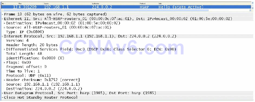
Figure 34.3 – HSRP Version 1 Multicast Group Address
While going into detail on the HSRP packet format is beyond the scope of the CCNA exam requirements, Figure 34.4 below illustrates the information contained in the HSRP version 1 packet:
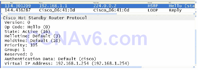
Figure 34.4 – The HSRP Version 1 Packet Fields
In Figure 34.4, notice that the Version field shows a value of 0. This is the default value for this field when version 1 is enabled; however, remember that this implies HSRP version 1.
HSRP Version 2
HSRP version 2 uses the new Multicast address 224.0.0.102 to send Hello packets instead of the Multicast address of 224.0.0.2, which is used by version 1. The UDP port number, however, remains the same. This new address is also encoded in both the IP packet and the Ethernet frame, as shown below in Figure 34.5:
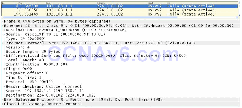
Figure 34.5 – HSRP Version 2 Multicast Group Address
While going into detail on the HSRP version 2 packet format is beyond the scope of the CCNA exam requirements, it is important to remember that HSRP version 2 does not use the same packet format as HSRP version 1.
The version 2 packet format uses a Type/Length/Value (TLV) format. HSRP version 2 packets received by an HSRP version 1 router will have the Type field mapped to the Version field by HSRP version 1 and will be subsequently ignored. Figure 34.6 illustrates the information contained in the HSRP version 2 packet:
HSRP Version 1 and Version 2 Comparison
HSRP version 2 includes enhancements to HSRP version 1. The version 2 enhancements and differences from version 1 will be described in this section.
Although HSRP version 1 advertises timer values, these values are always to the whole second, as it is not capable of advertising or learning millisecond timer values. Version 2 is capable of both advertising and learning millisecond timer values. Figures 34.7 and 34.8 below highlight the differences between the Timer fields for both HSRP version 1 and HSRP version 2, respectively:
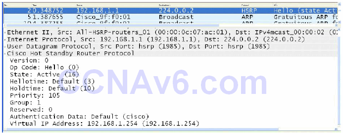
Figure 34.7 – HSRP Version 1 Timer Fields
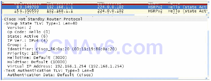
Figure 34.8 – HSRP Version 2 Timer Fields
HSRP version 1 group numbers are restricted to the range of 0 to 255, whereas the version 2 group numbers have been extended from 0 to 4095. This difference will be illustrated in the HSRP configuration examples that will be provided later in this module.
Version 2 provides improved management and troubleshooting by including a 6-byte Identifier field that is populated with the physical router interface MAC address and is used to uniquely identify the source of HSRP active Hello messages. In version 1, these messages contain the virtual MAC address as the source MAC, which means it is not possible to determine which HSRP router actually sent the HSRP Hello message. Figure 34.9 below shows the Identifier field that is present in the version 2 packet but not in the HSRP version 1 packet:
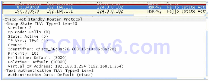
Figure 34.9 – HSRP Version 2 Identifier Field
In HSRP version 1, the Layer 2 address that is used by the virtual IP address will be a virtual MAC address composed of 0000.0C07.ACxx, where “xx” is the HSRP group number in hexadecimal value and is based on the respective interface. HSRP version 2, however, uses a new MAC address range of 0000.0C9F.F000 to 0000.0C9F.FFFF for the virtual gateway IP address. These differences are illustrated below in Figure 34.10, which shows the version 1 virtual MAC address for HSRP Group 1, as well as in Figure 34.11, which shows the version 2 virtual MAC address, also for HSRP Group 1:
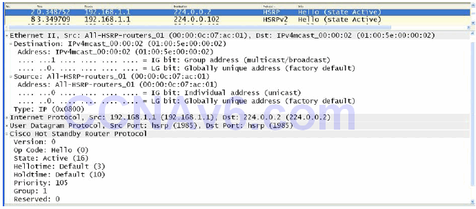
Figure 34.10 – HSRP Version 1 Virtual MAC Address Format
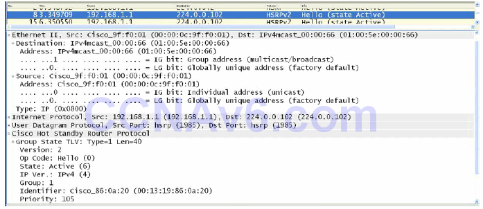
Figure 34.11 – HSRP Version 2 Virtual MAC Address Format
HSRP Primary Gateway Election
HSRP primary gateway election can be influenced by adjusting the default HSRP priority of 100 to any value between 1 and 255. The router with the highest priority will be elected as the primary gateway for the HSRP group.
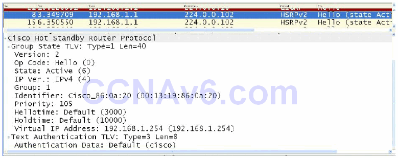
If two gateways are using the default priority values, or if the priority values on two gateways are manually configured as equal, the router with the highest IP address will be elected as the primary gateway. The HSRP priority value is carried in the HSRP frame, as is the current state of the router (e.g., primary or standby). Figure 34.12 below illustrates the Priority and State fields of a gateway configured with a non-default priority value of 105, which resulted in it being elected as the active gateway for the HSRP group:
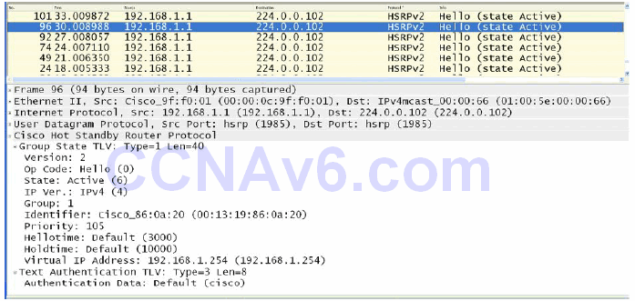
Figure 34.12 – HSRP Priority and State Fields
HSRP Messages
HSRP routers exchange the following three types of messages:
- Hello messages
- Coup messages
- Resign messages
Hello messages are exchanged via Multicast and they tell the other gateway the HSRP state and priority values of the local router. Hello messages also include the Group ID, HSRP timer values, version, and authentication information. All of the messages shown in the previous screenshots are HSRP Hello messages.
HSRP Coup messages are sent when the current standby router wants to assume the role of active gateway for the HSRP group. This is similar to a coup d’état in real life.
HSRP Resign messages are sent by the active router when it is about to shut down or when a gateway that has a higher priority sends a Hello or Coup message. In other words, this message is sent when the active gateway concedes its role as primary gateway.
HSRP Preemption
If a gateway has been elected as the active gateway and another gateway that is part of the HSRP group is reconfigured with a higher priority value, the current active gateway retains the primary forwarding role. This is the default behaviour of HSRP.
In order for a gateway with a higher priority to assume active gateway functionality when a primary gateway is already present for an HSRP group, the router must be configured for preemption. This allows the gateway to initiate a coup and assume the role of the active gateway for the HSRP group. HSRP preemption is illustrated in the configuration examples to follow.
NOTE: Preemption does not necessarily mean that the Spanning Tree topology changes also.
HSRP States
In a manner similar to Open Shortest Path First (OSPF), when HSRP is enabled on an interface, the gateway interface goes through the following series of states:
- Disabled
- Init
- Listen
- Speak
- Standby
- Active
NOTE: There are no set time values for these interface transitions.
In either the Disabled or the Init states, the gateway is not yet ready or is unable to participate in HSRP, possibly because the associated interface is not up.
The Listen state is applicable to the standby gateway. Only the standby gateway monitors Hello messages from the active gateway. If the standby gateway does not receive Hellos within 10 seconds, it assumes that the active gateway is down and takes on this role itself. If other gateways exist on the same segment, they also listen to Hellos and will be elected as the group active gateway if they have the next highest priority value or IP address.
During the Speak phase, the standby gateway exchanges messages with the active gateway. Upon completion of this phase, the primary gateway transitions to the Active state and the backup gateway transitions to the Standby state. The Standby state indicates that the gateway is ready to assume the role of active gateway if the primary gateway fails, and the Active state indicates that the gateway is ready to actively forward packets.
The following output shows the state transitions displayed in the debug standby command on a gateway for which HSRP has just been enabled:
R2#debug standby
HSRP debugging is on
R2#
R2#conf t
Configuring from terminal, memory, or network [terminal]?
Enter configuration commands, one per line. End with CNTL/Z.
R2(config)#logging con
R2(config)#int f0/0
R2(config-if)#stand 1 ip 192.168.1.254
R2(config-if)#
*Mar 1 01:21:55.471: HSRP: Fa0/0 API 192.168.1.254 is not an HSRP address
*Mar 1 01:21:55.471: HSRP: Fa0/0 Grp 1 Disabled -> Init
*Mar 1 01:21:55.471: HSRP: Fa0/0 Grp 1 Redundancy “hsrp-Fa0/0-1” state Disabled -> Init
*Mar 1 01:22:05.475: HSRP: Fa0/0 Interface up
...
[Truncated Output]
...
*Mar 1 01:22:06.477: HSRP: Fa0/0 Interface min delay expired
*Mar 1 01:22:06.477: HSRP: Fa0/0 Grp 1 Init: a/HSRP enabled
*Mar 1 01:22:06.477: HSRP: Fa0/0 Grp 1 Init -> Listen
*Mar 1 01:22:06.477: HSRP: Fa0/0 Redirect adv out, Passive, active 0 passive 1
...
[Truncated Output]
...
*Mar 1 01:22:16.477: HSRP: Fa0/0 Grp 1 Listen: d/Standby timer expired (unknown)
*Mar 1 01:22:16.477: HSRP: Fa0/0 Grp 1 Listen -> Speak
...
[Truncated Output]
...
*Mar 1 01:22:26.478: HSRP: Fa0/0 Grp 1 Standby router is local
*Mar 1 01:22:26.478: HSRP: Fa0/0 Grp 1 Speak -> Standby
*Mar 1 01:22:26.478: %HSRP-5-STATECHANGE: FastEthernet0/0 Grp 1 state Speak -> Standby
*Mar 1 01:22:26.478: HSRP: Fa0/0 Grp 1 Redundancy “hsrp-Fa0/0-1” state Speak -> Standby
HSRP Addressing
Earlier in this module, you learned that in HSRP version 1, the Layer 2 address that is used by the virtual IP address will be a virtual MAC address composed of 0000.0C07.ACxx, where “xx” is the HSRP group number in hexadecimal value and is based on the respective interface. HSRP version 2, however, uses a new MAC address range of 0000.0C9F.F000 to 0000.0C9F.FFFF for the virtual gateway IP address.
In some cases, it may not be desirable to use these default address ranges. An example would be a situation where several HSRP groups were configured on a router interface connected to a switch port that was configured for port security. In such a case, the router would use a different MAC address for each HSRP group, the result being multiple MAC addresses that would all need to be accommodated in the port security configuration. This configuration would have to be modified each time an HSRP group was added to the interface; otherwise, a port security violation would occur.
To address this issue, Cisco IOS software allows administrators to configure HSRP to use the actual MAC address of the physical interface on which it is configured. The result is that a single MAC address is used by all groups (i.e., the MAC address of the active gateway is used) and the port security configuration need not be modified each time an HSRP group is configured between the routers connected to the switches. This is performed via the standby use-bia interface configuration command. The following output illustrates the show standby command, which shows a gateway interface that is configured with two different HSRP groups:
Gateway-1#show standby
FastEthernet0/0 - Group 1
  State is Active
    8 state changes, last state change 00:13:07
  Virtual IP address is 192.168.1.254
  Active virtual MAC address is 0000.0c07.ac01
    Local virtual MAC address is 0000.0c07.ac01 (v1 default)
  Hello time 3 sec, hold time 10 sec
    Next hello sent in 2.002 secs
  Preemption disabled
  Active router is local
  Standby router is 192.168.1.2, priority 100 (expires in 9.019 sec)
  Priority 105 (configured 105)
  IP redundancy name is “hsrp-Fa0/0-1” (default)
FastEthernet0/0 - Group 2
  State is Active
    2 state changes, last state change 00:09:45
  Virtual IP address is 172.16.1.254
  Active virtual MAC address is 0000.0c07.ac02
    Local virtual MAC address is 0000.0c07.ac02 (v1 default)
  Hello time 3 sec, hold time 10 sec
    Next hello sent in 2.423 secs
  Preemption disabled
  Active router is local
In the output above, based on the default HSRP version, the virtual MAC address for HSRP Group 1 is 0000.0c07.ac01, while that for HSRP Group 2 is 0000.0c07.ac02. This means that the switch port that this gateway is connected to learns three different addresses: the actual or burnt-in MAC address assigned to the actual physical FastEthernet0/0 interface, the virtual MAC address for HSRP Group 1, and the virtual MAC address for HSRP Group 2.
The following output illustrates how to configure HSRP to use the actual MAC address of the gateway interface as the virtual MAC address of the different HSRP groups:
Gateway-1#conf
Configuring from terminal, memory, or network [terminal]?
Enter configuration commands, one per line. End with CNTL/Z.
Gateway-1(config)#int f0/0
Gateway-1(config-if)#standby use-bia
Gateway-1(config-if)#exit
Based on the configuration in the output above, the show standby command reflects the new MAC address for the HSRP group, as illustrated in the following output:
Gateway-1#show standby
FastEthernet0/0 - Group 1
  State is Active
    8 state changes, last state change 00:13:30
  Virtual IP address is 192.168.1.254
  Active virtual MAC address is 0013.1986.0a20
    Local virtual MAC address is 0013.1986.0a20 (bia)
  Hello time 3 sec, hold time 10 sec
    Next hello sent in 2.756 secs
  Preemption disabled
  Active router is local
  Standby router is 192.168.1.2, priority 100 (expires in 9.796 sec)
  Priority 105 (configured 105)
  IP redundancy name is “hsrp-Fa0/0-1” (default)
FastEthernet0/0 - Group 2
  State is Active
    2 state changes, last state change 00:10:09
  Virtual IP address is 172.16.1.254
  Active virtual MAC address is 0013.1986.0a20
    Local virtual MAC address is 0013.1986.0a20 (bia)
  Hello time 3 sec, hold time 10 sec
    Next hello sent in 0.188 secs
  Preemption disabled
  Active router is local
  Standby router is unknown
  Priority 105 (configured 105)
  IP redundancy name is “hsrp-Fa0/0-2” (default)
The MAC address used by both groups, 0013.1986.0a20, is the MAC address assigned to the physical gateway interface. This is illustrated in the following output:
Gateway-1#show interface FastEthernet0/0
FastEthernet0/0 is up, line protocol is up
  Hardware is AmdFE, address is 0013.1986.0a20 (bia 0013.1986.0a20)
  Internet address is 192.168.1.1/24
  MTU 1500 bytes, BW 100000 Kbit/sec, DLY 100 usec,
     reliability 255/255, txload 1/255, rxload 1/255
  Encapsulation ARPA, loopback not set
...
[Truncated Output]
NOTE: In addition to configuring HSRP to use the burnt-in address (BIA), administrators also have the option of statically specifying the MAC address that the virtual gateway should use via the standby [number] mac-address [mac] interface configuration command. This option is typically avoided, as it can result in duplicate MAC addresses in the switched network, which can cause severe network issues and possibly even an outage.
HSRP Plain Text Authentication
By default, HSRP messages are sent with the plain text key string “cisco” as a simple method to authenticate HSRP peers. If the key string in a message matches the key configured on an HSRP peer, the message is accepted. If not, HSRP ignores the unauthenticated message(s).
Plain text keys provide very little security because they can be “captured on the wire” using simple packet capture tools, such as Wireshark and Ethereal. Figure 34.13 below shows the default plain text authentication key used in HSRP messages:
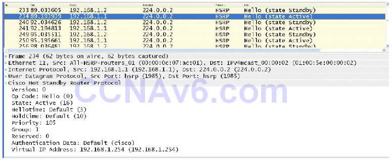
Figure 34.13 – Viewing the Default HSRP Plain Text Key
Because plain text authentication provides very little security, Message Digest 5 (MD5) authentication, which is described in the following section, is the recommended authentication method for HSRP.
HSRP MD5 Authentication
This isn’t a CCNA subject but it’s included here for completeness and for those of you who will be applying these lessons in your job on a live network.
Message Digest 5 authentication provides greater security for HSRP than that provided by plain text authentication by generating an MD5 digest for the HSRP portion of the Multicast HSRP protocol packet. Using MD5 authentication allows each HSRP group member to use a secret key to generate a keyed MD5 hash that is part of the outgoing packet. A keyed hash of the incoming HSRP packet is generated and if the hash within the incoming packet does not match the MD5-generated hash, the packet is simply ignored by the receiving router.
The key for the MD5 hash can be either given directly in the configuration using a key string or supplied indirectly through a key chain. Both configuration options will be described in detail later in this module. When using plain-text or MD5 authentication, the gateway will reject HSRP packets if any of the following is true:
- The authentication schemes differ on the router and in the incoming packets
- The MD5 digests differ on the router and in the incoming packets
- The text authentication strings differ on the router and in the incoming packets
HSRP Interface Tracking
HSRP allows administrators to track the status of interfaces on the current active gateway so that when that interface fails, the gateway decrements its priority by a specified value, the default being 10, allowing another gateway to assume the role of active gateway for the HSRP group. This concept is illustrated below in Figure 34.14:
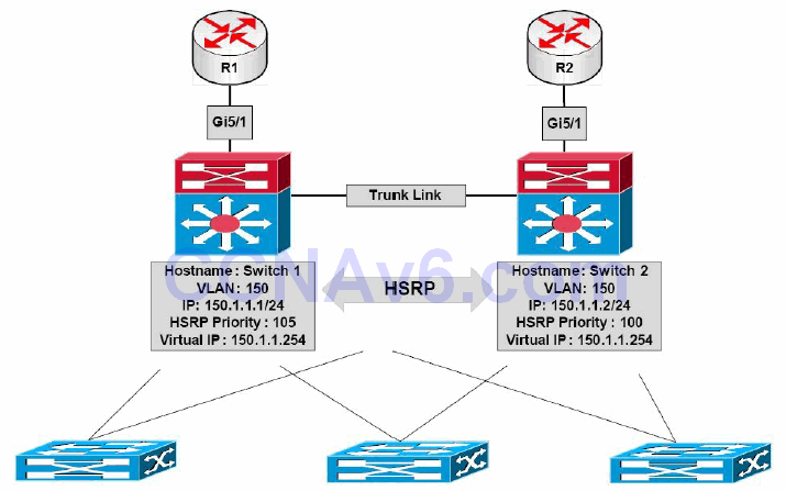
Figure 34.14 – HSRP Interface Tracking
Referencing Figure 34.14, HSRP has been enabled on Switch 1 and Switch 2 for VLAN 150. Based on the current priority configuration, Switch 1, with a priority value of 105, has been elected as the primary switch for this VLAN. Both Switch 1 and Switch 2 are connected to two routers via their GigabitEthernet5/1 interfaces. It is assumed that these two routers peer with other external networks, such as the Internet.
Without HSRP interface tracking, if the GigabitEthernet5/1 interface between Switch 1 and R1 failed, Switch 1 would retain its primary gateway status. It would then have to forward any received packets destined for the Internet, for example, over to Switch 2 using the connection between itself and Switch 2. The packets would be forwarded out via R2 towards their intended destination. This results in a suboptimal traffic path within the network.
HSRP interface tracking allows the administrators to configure HSRP to track the status of an interface and decrement the active gateway priority by either a default value of 10 or a value specified by the administrators. Referencing Figure 34.14, if HSRP interface tracking was configured using the default values on Switch 1, allowing it to track the status of interface GigabitEthernet5/1, and that interface failed, Switch 1 would decrement its priority for the HSRP group by 10, resulting in a priority of 95.
Assuming that Switch 2 was configured to preempt, which is mandatory in this situation, it would realise that it had the higher priority (100 versus 95) and perform a coup, assuming the role of active gateway for this HSRP group.
Real-World Implementation
In production networks, Cisco Catalyst switches also support Enhanced Object Tracking (EOT), which can be used with any FHRP (i.e., HSRP, VRRP, and GLBP). Enhanced Object Tracking allows administrators to configure the switch to track the following parameters:
- The IP routing state of an interface
- IP route reachability
- The threshold of IP route metrics
- IP SLA operations
FHRPs, such as HSRP, can be configured to track these enhanced objects, allowing for greater flexibility when implementing FHRP failover situations. For example, using EOT, the active HSRP router could be configured to decrement its priority value by a certain amount if a network or host route was not reachable (i.e., present in the routing table). EOT is beyond the scope of the CCNA exam requirements and will not be illustrated in the configuration examples.
HSRP Load Balancing
HSRP allows administrators to configure multiple HSRP groups on physical interfaces to allow for load balancing. By default, when HSRP is configured between two gateways, only one gateway actively forwards traffic for that group at any given time. This can result in wasted bandwidth for the standby gateway link. This is illustrated below in Figure 34.15:
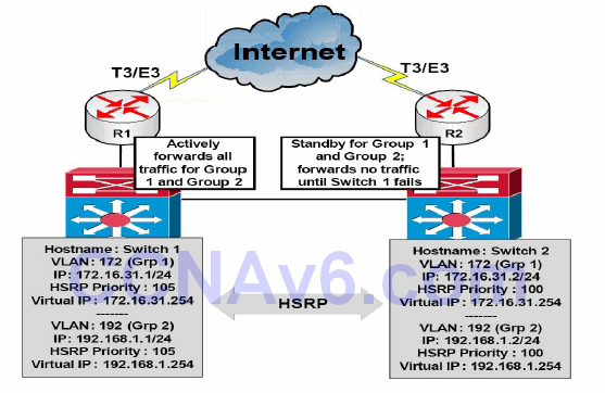
Figure 34.15 – A Network without HSRP Load Balancing
In Figure 34.15, two HSRP groups are configured between Switch 1 and Switch 2. Switch 1 has been configured as the active (primary) gateway for both groups – based on the higher priority value. Switch 1 and Switch 2 are connected to R1 and R2, respectively. These routers are both connected to the Internet via T3/E3 dedicated lines. Because Switch 1 is the active gateway for both groups, it will forward traffic for both groups until it fails and Switch 2 will then assume the role of active (primary) gateway.
While this does satisfy the redundancy needs of the network, it also results in the expensive T3/E3 link on R2 remaining idle until Switch 2 becomes the active gateway and begins to forward traffic through it. Naturally, this represents a wasted amount of bandwidth.
By configuring multiple HSRP groups, each using a different active gateway, administrators can effectively prevent the unnecessary waste of resources and load balance between Switch 1 and Switch 2. This is illustrated below in Figure 34.16:
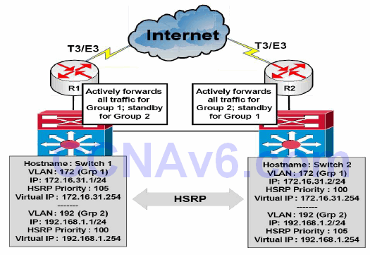
Figure 34.16 – A Network Using HSRP for Load Balancing
By configuring Switch 1 as the active gateway for HSRP Group 1 and Switch 2 as the active gateway for HSRP Group 2, administrators can allow traffic from these two groups to be load balanced between Switch 1 and Switch 2, and ultimately across the two dedicated T3/E3 WAN connections. Each switch then backs up the other’s group. For example, Switch 1 will assume the role of active gateway for Group 2 if Switch 2 fails, and vice versa.
Real-World Implementation
In production networks, it is important to remember that creating multiple HSRP groups may result in increased gateway CPU utilisation, as well as increased network utilisation due to HSRP message exchanges. Cisco Catalyst switches, such as the Catalyst 4500 and 6500 series switches, support the implementation of HSRP client groups.
In the previous section, you learned that HSRP allows for the configuration of multiple groups on a single gateway interface. The primary issue with running many different HSRP groups on the gateway interface is that it increases CPU utilisation on the gateway and may potentially also increase the amount of network traffic, given the 3-second Hello interval used by HSRP.
To address this potential issue, HSRP also allows for the configuration of client or slave groups. These are simply HSRP groups that are configured to follow a master HSRP group and that do not participate in the HSRP election. These client or slave groups follow the operation and HSRP status of the master group and, therefore, do not need to exchange periodic Hello packets themselves. This reduces CPU and network utilisation when using multiple HSRP groups.
However, it should be noted that client groups send periodic messages in order to refresh their virtual MAC addresses in switches. The refresh message may be sent at a much lower frequency compared with the protocol election messages sent by the master group. While the configuration of client groups is beyond the scope of the CCNA exam requirements, the following output illustrates the configuration of two client groups, which are configured to follow master group HSRP Group 1, also named the SWITCH-HSRP group:
Gateway-1(config)#interface vlan100
Gateway-1(config-if)#ip address 192.168.1.1 255.255.255.0
Gateway-1(config-if)#ip address 172.16.31.1 255.255.255.0 secondary
Gateway-1(config-if)#ip address 10.100.10.1 255.255.255.0 secondary
Gateway-1(config-if)#standby 1 ip 192.168.1.254
Gateway-1(config-if)#standby 1 name SWITCH-HSRP
Gateway-1(config-if)#standby 2 ip 172.16.31.254
Gateway-1(config-if)#standby 2 follow SWITCH-HSRP
Gateway-1(config-if)#standby 3 ip 10.100.10.254
Gateway-1(config-if)#standby 3 follow SWITCH-HSRP
Gateway-1(config-if)#exit
In the configuration in the output above, Group 1 is configured as the master HSRP group and Groups 2 and 3 are configured as client or slave HSRP groups.
Configuring HSRP on the Gateway
The following steps are required to configure HSRP on the gateway:
- Configure the correct IP address and mask for the gateway interface using the ip address [address] [mask] [secondary] interface configuration command.
- Create an HSRP group on the gateway interface and assign the group the virtual IP address via the standby [number] ip [virtual address][secondary] interface configuration command. The [secondary] keyword specifies the IP address as a secondary gateway IP address for the specified group.
- Optionally, assign the HSRP group a name using the standby [number] name [name] interface configuration command.
- Optionally, if you want to control the election of the active gateway, configure the grouppriority via the standby [number] priority [value] interface configuration command.
The following HSRP configuration outputs in this section will be based on the network below in Figure 34.17:

Figure 34.17 – HSRP Configuration Examples Topology
NOTE: It is assumed that the VLAN and trunking configuration between VTP-Server-1 and VTP-Server-2 is already in place and the switches are successfully able to ping each other across VLAN172. For brevity, this configuration output will be omitted from the configuration examples.
VTP-Server-1(config)#interface vlan172
VTP-Server-1(config-if)#ip address 172.16.31.1 255.255.255.0
VTP-Server-1(config-if)#standby 1 ip 172.16.31.254
VTP-Server-1(config-if)#standby 1 priority 105
VTP-Server-1(config-if)#exit
VTP-Server-2(config)#interface vlan172
VTP-Server-2(config-if)#ip address 172.16.31.2 255.255.255.0
VTP-Server-2(config-if)#standby 1 ip 172.16.31.254
VTP-Server-2(config-if)#exit
NOTE: No priority value is manually assigned for the HSRP configuration applied to VTP-Server-2. By default, HSRP will use a priority value of 100, allowing VTP-Server-1, with a priority value of 105, to win the election and to be elected the primary gateway for the HSRP group.
Once implemented, HSRP configuration may be validated using the show standby [interface brief] command. The show standby brief command is shown in the following outputs:
VTP-Server-1#show standby brief
                     P indicates configured to preempt.
                     |
Interface   Grp  Pri P State   Active  Standby         Virtual IP
Vl172       1    105   Active  local   172.16.31.2     172.16.31.254
VTP-Server-2#show standby brief
                     P indicates configured to preempt.
                     |
Interface   Grp  Pri P State    Active  Standby       Virtual IP
Vl172       1    100   Standby  local   172.16.31.1   172.16.31.254
Based on this configuration, VTP-Server-2 will become the active gateway for this group only if VTP-Server-1 fails. Additionally, because preemption is not configured, when VTP-Server-1 comes back online, it will not be able to assume forcefully the role of active gateway, even though it has a higher priority for the HSRP group than that being used on VTP-Server-2.
Configuring HSRP Preemption
Preemption allows a gateway to assume forcefully the role of active gateway if it has a higher priority than the current active gateway. HSRP preemption is configured using the standby [number] preempt command. This configuration is illustrated on VTP-Server-1 in the following output:
VTP-Server-1(config)#interface vlan172
VTP-Server-1(config-if)#standby 1 preempt
The show standby [interface [name]|brief] command is also used to verify that preemption has been configured on a gateway. This is illustrated by the “P” shown in the output of the show standby brief command below:
VTP-Server-1#show standby brief
                     P indicates configured to preempt.
                     |
Interface   Grp  Pri P State   Active  Standby         Virtual IP
Vl172       1    105 P Active  local   172.16.31.2     172.16.31.254
Based on this modification, if VTP-Server-1 did fail and VTP-Server-2 assumed the role of active gateway for VLAN 172, VTP-Server-1 could forcibly reassume that role once it reinitialises. When configuring preemption, Cisco IOS software allows you to specify the duration the switch must wait before it preempts and forcibly reassumes the role of active gateway.
By default, this happens immediately. However, it may be adjusted using the standby [number] preempt delay [minimum|reload|sync] interface configuration command. The [minimum] keyword is used to specify the minimum amount of time to wait (seconds) before preemption. The following output shows how to configure the gateway to wait 30 seconds before preemption:
VTP-Server-1(config)#interface vlan172
VTP-Server-1(config-if)#standby 1 preempt delay minimum 30
This configuration may be validated using the show standby [interface] command. This is illustrated in the following output:
VTP-Server-1#show standby vlan172
Vlan172 - Group 1
  State is Active
    5 state changes, last state change 00:00:32
  Virtual IP address is 172.16.31.254
  Active virtual MAC address is 0000.0c07.ac01
    Local virtual MAC address is 0000.0c07.ac01 (v1 default)
  Hello time 3 sec, hold time 10 sec
    Next hello sent in 0.636 secs
  Preemption enabled, delay min 30 secs
  Active router is local
  Standby router is 172.16.31.2, priority 100 (expires in 8.629 sec)
  Priority 105 (configured 105)
  IP redundancy name is “hsrp-Vl172-1” (default)
The [reload] keyword is used to specify the amount of time the gateway should wait after it initialises following a reload. The [sync] keyword is used in conjunction with IP redundancy clients. This configuration is beyond the scope of the CCNA exam requirements but is very useful in production environments because it prevents an unnecessary change of roles in the case of a flapping interface that is being tracked, or similar activity.
Configuring HSRP Interface Tracking
HSRP interface tracking allows administrators to configure HSRP in order to track the state of interfaces and decrement the current priority value by the default value (10) or a preconfigured value, allowing another gateway to assume the role of primary gateway for the specified HSRP group.
In the following output, VTP-Server-1 is configured to track the state of interface GigabitEthernet5/1, which is connected to an imaginary WAN router. In the event that the state of that interface transitions to “down,” the gateway will decrement its priority value by 10 (which is the default):
VTP-Server-1(config)#interface vlan172
VTP-Server-1(config-if)#standby 1 track GigabitEthernet5/1
This configuration may be validated using the show standby [interface] command. This is illustrated in the following output:
VTP-Server-1#show standby vlan172
Vlan172 - Group 1
  State is Active
    5 state changes, last state change 00:33:22
  Virtual IP address is 172.16.31.254
  Active virtual MAC address is 0000.0c07.ac01
    Local virtual MAC address is 0000.0c07.ac01 (v1 default)
  Hello time 3 sec, hold time 10 sec
    Next hello sent in 1.085 secs
  Preemption enabled
  Active router is local
  Standby router is 172.16.31.2, priority 100 (expires in 7.616 sec)
  105 (configured 105)
  Priority tracking 1 interfaces or objects, 1 up:
  GigabitEthernet5/1            10         Up
To configure the gateway to decrement its priority value by 50, for example, the standby [name] track [interface] [decrement value] command can be issued, as shown in the following output:
VTP-Server-1(config)#interface vlan172
VTP-Server-1(config-if)#standby 1 track GigabitEthernet5/1 50
This configuration may be validated using the show standby [interface] command. This is illustrated in the following output:
VTP-Server-1#show standby vlan172
Vlan172 - Group 1
  State is Active
    5 state changes, last state change 00:33:22
  Virtual IP address is 172.16.31.254
  Active virtual MAC address is 0000.0c07.ac01
    Local virtual MAC address is 0000.0c07.ac01 (v1 default)
  Hello time 3 sec, hold time 10 sec
    Next hello sent in 1.085 secs
  Preemption enabled
  Active router is local
  router is 172.16.31.2, priority 100 (expires in 7.616 sec)
  IP redundancy name is “hsrp-Vl172-1” (default)
  Interface or object           Decrement  State
  GigabitEthernet5/1            50         Up
Configuring the HSRP Version
As stated previously in this module, by default, when HSRP is enabled, version 1 is enabled. HSRP version 2 can be manually enabled using the standby version [1|2] interface configuration command. HSRP version 2 configuration is illustrated in the following output:
VTP-Server-1(config)#interface vlan172
VTP-Server-1(config-if)#standby version 2
This configuration may be validated using the show standby [interface] command. This is illustrated in the following output:
VTP-Server-1#show standby vlan172
Vlan172 - Group 1 (version 2)
  State is Active
    5 state changes, last state change 00:43:42
  Virtual IP address is 172.16.31.254
  Active virtual MAC address is 0000.0c9f.f001
    Local virtual MAC address is 0000.0c9f.f001 (v2 default)
  Hello time 3 sec, hold time 10 sec
    Next hello sent in 2.419 secs
  Preemption enabled
  Active router is local
  Standby router is 172.16.31.2, priority 100 (expires in 4.402 sec)
  Priority 105 (configured 105)
  IP redundancy name is “hsrp-Vl172-1” (default)
Enabling HSRP automatically changes the MAC address range used by HSRP from an address in the 0000.0C07.ACxx range to one in the 0000.0C9F.F000 to 0000.0C9F.FFFF range. It is therefore important to understand that this may cause some packet loss in a production network, as devices must learn the new MAC address of the gateway. Such changes are always recommended during a maintenance window or planned outage window.
Virtual Router Redundancy Protocol
Virtual Router Redundancy Protocol (VRRP) is a gateway election protocol that dynamically assigns responsibility for one or more virtual gateways to the VRRP routers on a LAN, which allows several routers on a Multi-Access segment, such as Ethernet, to use the same virtual IP address as their default gateway.
VRRP operates in a similar manner to HSRP; however, unlike HSRP, VRRP is an open standard that is defined in RFC 2338, which was made obsolete by RFC 3768. VRRP sends advertisements to the Multicast destination address 224.0.0.18 (VRRP), using IP protocol number 112. At the Data Link Layer, advertisements are sent from the master virtual router MAC address 00-00-5e- 00-01xx, where “xx” represents the two-digit hexadecimal group number. This is illustrated below in Figure 34.18:
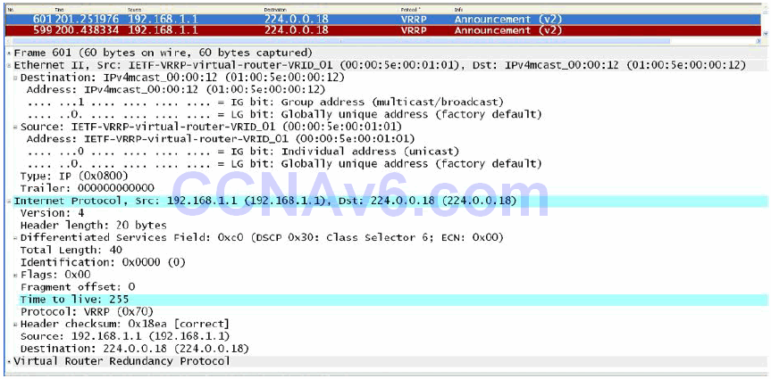
Figure 34.18 – VRRP Multicast Addresses
NOTE: The protocol number is in hexadecimal value. The hexadecimal value 0x70 is the equivalent of the decimal value 112. Similarly, the 12 in the destination Data Link Layer address 01-00-5e-00-00-12 is the hexadecimal value of 18 in decimal value (i.e., 224.0.0.18). If you are unable to determine how these values are reached, hexadecimal to decimal conversion is covered in detail in the current CCNA guide that is available online.
Real-World Implementation
Unlike HSRP, VRRP does not have the option of allowing the gateway to use the BIA or a statically configured address as the MAC address for VRRP groups. Therefore, in production networks with more than one VRRP group, it is important to understand the implications of multiple MAC addresses on a particular interface, especially when features such as port security have been implemented. Remember to look at the overall picture; otherwise, you may find that, even though correctly configured, certain features and protocols are not working as they should.
A VRRP gateway is configured to run the VRRP protocol in conjunction with one or more other routers attached to a LAN. In a VRRP configuration, one gateway is elected as the master virtual router, with the other gateways acting as backup virtual routers in case the master virtual router fails. This concept is illustrated below in Figure 34.19:
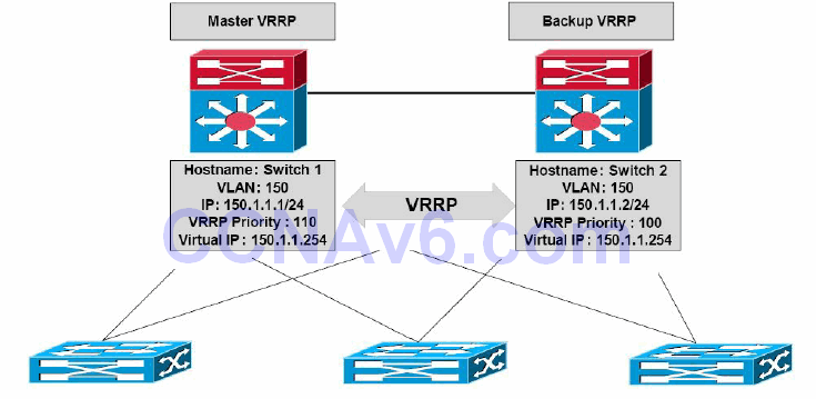
Figure 34.19 – VRRP Basic Operation
VRRP Multiple Virtual Router Support
You can configure up to 255 virtual routers on an interface. The actual number of virtual routers that a router interface can support depends upon the following factors:
- Router processing capability
- Router memory capability
- Router interface support of multiple MAC addresses
VRRP Master Router Election
By default, VRRP uses priority values to determine which router will be elected as the master virtual router. The default VRRP priority value is 100; however, this value can be manually adjusted to a value between 1 and 254. If gateways have the same priority values, the gateway with the highest IP address will be elected as the master virtual router, while the one with the lower IP address becomes the backup virtual router.
If more than two routers are configured as part of the VRRP group, the backup virtual router with the second-highest priority is elected as the master virtual router if the current master virtual router fails or becomes unavailable. If the backup virtual routers have the same priority value, the backup virtual router with the highest IP address is elected as the master virtual router. This concept is illustrated below in Figure 34.20:
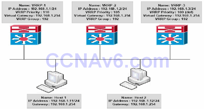
Figure 34.20 – VRRP Master Virtual Router and Backup Virtual Router Election
Figure 34.20 illustrates a network using VRRP for gateway redundancy. Hosts 1 and 2 are configured with a default gateway of 192.168.1.254, which is the virtual IP address configured for VRRP group 192 defined on Switches VRRP-1, VRRP-2, and VRRP-3.
VRRP-1 has a configured priority value of 110, VRRP-2 has a configured priority value of 105, and VRRP-3 is using the default VRRP priority of 100. Based on this configuration, VRRP-1 is elected as the master virtual router and VRRP-2 and VRRP-3 become backup virtual routers.
In the event that VRRP-1 fails, VRRP-2 becomes the master virtual router because it has a higher priority value than VRRP-3. However, if both switches had the same priority value, VRRP-3 would be elected as the master virtual router because it has the higher IP address.
VRRP Preemption
By default, unlike HSRP, preemption is enabled for VRRP and no explicit configuration is required by the administrator to enable this functionality. However, this functionality can be disabled by using the no vrrp [number] preempt interface configuration command.
VRRP Load Balancing
VRRP allows for load balancing in a manner similar to HSRP. For example, in a network where multiple virtual routers are configured on a gateway, the interface can act as a master for one virtual router and as a backup for one or more virtual routers. This is illustrated below in Figure 34.21:
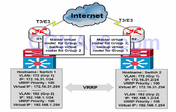
Figure 34.21 – VRRP Load Balancing
VRRP Versions
By default, VRRP version 2 (see Figure 34.22 below) is enabled when VRRP is configured on a gateway in Cisco IOS software. Version 2 is the default and current VRRP version. It is not possible to change the version as is the case with HSRP. There is no VRRP version 1 standard.
NOTE: As of the time this guide was written, VRRP version 3, which defines the VRRP for IPv4 and IPv6, is in draft form and has not yet been standardised.
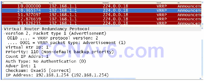
Figure 34.22 – VRRP Version 2 Packet
VRRP Advertisements
The master virtual router sends advertisements to other VRRP routers in the same group. The advertisements communicate the priority and the state of the master virtual router. The VRRP advertisements are encapsulated in IP packets and are sent to the IPv4 Multicast address assigned to the VRRP group, which was illustrated in Figure 34.18. The advertisements are sent every second by default; however, this interval is user-configurable and may be changed.
Backup virtual routers also optionally learn the advertisement interval from the master virtual router.
Configuring VRRP on the Gateway
The following steps are required to configure VRRP on the gateway:
- Configure the correct IP address and mask for the gateway interface using the ip address [address] [mask] [secondary] interface configuration command.
- Create a VRRP group on the gateway interface and assign the group the virtual IP address via the vrrp [number] ip [virtual address][secondary] interface configuration command. The [secondary] keyword configures the virtual IP address as a secondary gateway address for the specified group.
- Optionally, assign the VRRP group a description using the vrrp [number] description[name] interface configuration command.
- Optionally, if you want to control the elections of the master virtual router and the backup virtual routers, configure the group priority via the vrrp [number] priority [value] interface configuration command.
The VRRP configuration outputs in this section will be based on Figure 34.23 below:

Figure 34.23 – VRRP Configuration Examples Topology
NOTE: It is assumed that the VLAN and trunking configuration between VTP-Server-1 and VTP-Server-2 is already in place and the switches are successfully able to ping each other across VLAN172. For brevity, this configuration output will be omitted from the configuration examples.
VTP-Server-1(config)#interface vlan192
VTP-Server-1(config-if)#ip address 192.168.1.1 255.255.255.0
VTP-Server-1(config-if)#vrrp 1 ip 192.168.1.254
VTP-Server-1(config-if)#vrrp 1 priority 105
VTP-Server-1(config-if)#vrrp 1 description ‘SWITCH-VRRP-Example’
VTP-Server-1(config-if)#exit
VTP-Server-2(config)#interface vlan192
VTP-Server-2(config-if)#ip address 192.168.1.2 255.255.255.0
VTP-Server-2(config-if)#vrrp 1 ip 192.168.1.254
VTP-Server-2(config-if)#vrrp 1 description ‘SWITCH-VRRP-Example’
VTP-Server-2(config-if)#exit
NOTE: No priority value is manually assigned for the VRRP configuration applied to VTP-Server-2. By default, VRRP will use a priority value of 100, allowing VTP-Server-1, with a priority value of 105, to win the election and to be elected as the master virtual router for the VRRP group. In addition, a description has also optionally been configured for the group.
This configuration is validated using the show vrrp [all|brief|interface] command. The [all] keyword shows all information pertaining to the VRRP configuration, which includes the group state, description (if configured), local gateway priority, and master virtual router, among other things. The [brief] keyword prints a summary of the VRRP configuration. The [interface] keyword prints VRRP information for the specified interface. The following outputs show the show vrrp all command:
VTP-Server-1#show vrrp all
Vlan192 - Group 1
‘SWITCH-VRRP-Example’
  State is Master
  Virtual IP address is 192.168.1.254
  Virtual MAC address is 0000.5e00.0101
  Advertisement interval is 1.000 sec
  Preemption enabled
  Priority is 105
  Master Router is 192.168.1.1 (local), priority is 105
  Advertisement interval is 1.000 sec
  Master Down interval is 3.589 sec
VTP-Server-2#show vrrp all
Vlan192 - Group 1
‘SWITCH-VRRP-Example’
  State is Backup
  Virtual IP address is 192.168.1.254
  Virtual MAC address is 0000.5e00.0101
  Advertisement interval is 1.000 sec
  Preemption enabled
  Priority is 100
  Master Router is 192.168.1.1, priority is 105
  Master Advertisement interval is 1.000 sec
  Master Down interval is 3.609 sec (expires in 3.328 sec)
The following outputs show the information printed by the show vrrp brief command:
VTP-Server-1#show vrrp brief
VTP-Server-1#show vrrp brief
Interface          Grp Pri Time  Own Pre State   Master addr     Group addr
Vl192              1   105 3589       Y  Master  192.168.1.1     192.168.1.254
VTP-Server-2#show vrrp brief
Interface          Grp Pri Time  Own Pre State   Master addr     Group addr
Vl192              1   100 3609       Y  Backup  192.168.1.1     192.168.1.254
Configuring VRRP Interface Tracking
In order to configure VRRP to track an interface, a tracked object must be created in Global Configuration mode using the track [object number] interface [line-protocol|ip routing] global configuration command for interface tracking or the track [object number] ip route [address | prefix] [reachability | metric threshold] command for IP prefix tracking. Up to 500 tracked objects may be tracked on the switch, depending on the software and platform. Tracked objects are then tracked by VRRP using the vrrp [number] track [object] interface configuration command.
NOTE: You are not expected to perform any advanced object tracking configurations.
The following output shows how to configure tracking for VRRP, referencing object 1, which tracks the line protocol of the Loopback0 interface:
VTP-Server-1(config)#track 1 interface Loopback0 line-protocol
VTP-Server-1(config-track)#exit
VTP-Server-1(config)#interface vlan192
VTP-Server-1(config-if)#vrrp 1 track 1
VTP-Server-1(config-if)#exit
The following output shows how to configure tracking for VRRP, referencing object 2, which tracks the reachability of the 1.1.1.1/32 prefix. A tracked IP route object is considered to be up and reachable when a routing table entry exists for the route and the route is not inaccessible (i.e., has a route metric of 255), in which case the route is removed from the Routing Information Base (RIB) anyway:
VTP-Server-1(config)#track 2 ip route 1.1.1.1/32 reachability
VTP-Server-1(config-track)#exit
VTP-Server-1(config)#interface vlan192
VTP-Server-1(config-if)#vrrp 1 track 2
VRRP tracking configuration is verified using the show vrrp interface [name] command. This is illustrated in the following output:
VTP-Server-1#show vrrp interface vlan192
Vlan192 - Group 1
‘SWITCH-VRRP-Example’
  State is Master
  Virtual IP address is 192.168.1.254
  Virtual MAC address is 0000.5e00.0101
  Advertisement interval is 0.100 sec
  Preemption enabled
  Priority is 105
    Track object 1 state Up decrement 10
    Track object 2 state Up decrement 10
  Authentication MD5, key-string
  Master Router is 192.168.1.1 (local), priority is 105
  Master Advertisement interval is 0.100 sec
  Master Down interval is 0.889 sec
To view the parameters of the tracked objects, use the show track [number][brief] [interface] [ip] [resolution][timers] command. The output of the show track command is illustrated as follows:
VTP-Server-1#show track
Track 1
  Interface Loopback0 line-protocol
  Line protocol is Up
    1 change, last change 00:11:36
  Tracked by:
    VRRP Vlan192 1
Track 2
  IP route 1.1.1.1 255.255.255.255 reachability
  Reachability is Up (connected)
    1 change, last change 00:08:48
  First-hop interface is Loopback0
  Tracked by:
    VRRP Vlan192 1
NOTE: Tracked objects can also be used in conjunction with HSRP and GLBP. GLBP is described in a section to follow.
Debugging VRRP
The debug vrrp command provides several options that the administrator can use to view realtime information on VRRP operation. These options are illustrated in the following output:
all      Debug all VRRP information
auth     VRRP authentication reporting
errors   VRRP error reporting
events   Protocol and Interface events
packets  VRRP packet details
state    VRRP state reporting
track    Monitor tracking
<cr>
Gateway Load Balancing Protocol
Like HSRP, Gateway Load Balancing Protocol (GLBP) is a Cisco proprietary protocol. GLBPprovides high network availability in a manner similar to HSRP and VRRP. However, unlike HSRP and VRRP, in which only a single gateway actively forwards traffic for a particular group at any given time, GLBP allows multiple gateways within the same GLBP group to actively forward network traffic at the same time.
GLBP gateways communicate through Hello messages that are sent every three seconds to the Multicast address 224.0.0.102, using UDP port 3222. This is illustrated below in Figure 34.24:
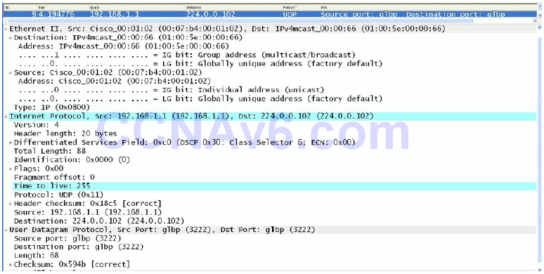
Figure 34.24 – GLBP Layer 3 and Layer 4 Protocols and Addresses
GLBP Operation
When GLBP is enabled, the GLBP group members elect one gateway to be the active virtual gateway (AVG) for that group. The AVG is the gateway that has the highest priority value. In the event that the priority values are equal, the AVG with the highest IP address in the group will be elected as the gateway. The other gateways in the GLBP group provide backup for the AVG in the event that the AVG becomes unavailable.
The AVG answers all Address Resolution Protocol (ARP) requests for the virtual router address. In addition, the AVG assigns a virtual MAC address to each member of the GLBP group. Each gateway is therefore responsible for forwarding packets that are sent to the virtual MAC address which has been assigned by the AVG. These gateways are referred to as active virtual forwarders (AVFs) for their assigned MAC addresses. This allows GLBP to provide load sharing. This concept is illustrated below in Figure 34.25:
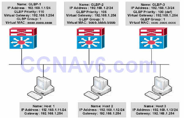
Figure 34.25 – GLBP Active Virtual Gateway and Active Virtual Forwarders
Figure 34.25 shows a network using GLBP as the FHRP. The three gateways are all configured in GLBP Group 1. Gateway GLBP-1 is configured with a priority of 110, gateway GLBP-2 is configured with a priority of 105, and gateway GLBP-3 is using the default priority of 100. GLBP- 1 is elected AVG, and GLBP-2 and GLBP-3 are assigned virtual MAC addresses bbbb.bbbb.bbbb and cccc.cccc.cccc, respectively, and become AVFs for those virtual MAC addresses. GLBP-1 is also the AVF for its own virtual MAC address, aaaa.aaaa.aaaa.
Hosts 1, 2, and 3 are all configured with the default gateway address 192.168.1.254, which is the virtual IP address assigned to the GLBP group. Host 1 sends out an ARP Broadcast for its gateway IP address. This is received by the AVG (GLBP-1), which responds with its own virtual MAC address aaaa.aaaa.aaaa. Host 1 forwards traffic to 192.168.1.254 to this MAC address.
Host 2 sends out an ARP Broadcast for its gateway IP address. This is received by the AVG (GLBP-1), which responds with the virtual MAC address of bbbb.bbbb.bbbb (GLBP-2). Host 2 forwards traffic to 192.168.1.254 to this MAC address and GLBP-2 forwards this traffic.
Host 3 sends out an ARP Broadcast for its gateway IP address. This is received by the AVG (GLBP-1), which responds with the virtual MAC address of cccc.cccc.cccc (GLBP-3). Host 3
forwards traffic to 192.168.1.254 to this MAC address and GLBP-3 forwards this traffic. By using all gateways in the group, GLBP allows for load sharing without having to configure multiple groups as would be required if either HSRP or VRRP was being used as the FHRP.
GLBP Virtual MAC Address Assignment
A GLBP group allows up to four virtual MAC addresses per group. The AVG is responsible for assigning the virtual MAC addresses to each member of the group. Other group members request a virtual MAC address after they discover the AVG through Hello messages.
Gateways are assigned the next virtual MAC address in sequence. A gateway that is assigned a virtual MAC address by the AVG is known as a primary virtual forwarder, while a gateway that has learned the virtual MAC address is referred to as a secondary virtual forwarder.
GLBP Redundancy
Within the GLBP group, a single gateway is elected as the AVG, and another gateway is elected as the standby virtual gateway. All other remaining gateways in the group are placed in a Listen state. If an AVG fails, the standby virtual gateway will assume responsibility for the virtual IP address. At the same time, an election is held and a new standby virtual gateway is then elected from the gateways currently in the Listen state.
In the event the AVF fails, one of the secondary virtual forwarders in the Listen state assumes responsibility for the virtual MAC address. However, because the new AVF is already a forwarder using another virtual MAC address, GLBP needs to ensure that the old forwarder MAC address ceases being used and hosts are migrated away from this address. This is achieved using the following two timers:
- The redirect timer
- The timeout timer
The redirect time is the interval during which the AVG continues to redirect hosts to the old virtual forwarder MAC address. When this timer expires, the AVG stops using the old virtual forwarder MAC address in ARP replies, although the virtual forwarder will continue to forward packets that were sent to the old virtual forwarder MAC address.
When the timeout timer expires, the virtual forwarder is removed from all gateways in the GLBP group. Any clients still using the old MAC address in their ARP caches must refresh the entry to obtain the new virtual MAC address. GLBP uses Hello messages to communicate the current state of these two timers.
GLBP Load Preemption
By default, GLBP preemption is disabled, which means that a backup virtual gateway can become the AVG only if the current AVG fails, regardless of the priorities assigned to the virtual gateways. This method of operation is similar to that used by HSRP.
Cisco IOS software allows administrators to enable preemption, which allows a backup virtual gateway to become the AVG if the backup virtual gateway is assigned a higher priority than the current AVG. By default, the GLBP virtual forwarder preemptive scheme is enabled with a delay of 30 seconds. However, this value can be manually adjusted by administrators.
GLBP Weighting
GLBP uses a weighting scheme to determine the forwarding capacity of each gateway that is in the GLBP group. The weighting assigned to a gateway in the GLBP group can be used to determine whether it will forward packets and, if so, the proportion of hosts in the LAN for which it will forward packets.
By default, each gateway is assigned a weight of 100. Administrators can additionally configure the gateways to make dynamic weighting adjustments by configuring object tracking, such as for interfaces and IP prefixes, in conjunction with GLBP. If an interface fails, the weighting is dynamically decreased by the specified value, allowing gateways with higher weighting values to be used to forward more traffic than those with lower weighting values.
In addition, thresholds can be set to disable forwarding when the weighting for a GLBP group falls below a certain value, and then when it rises above another threshold, forwarding is automatically re-enabled. A backup virtual forwarder can become the AVF if the current AVF weighting falls below the low weighting threshold for 30 seconds.
GLBP Load Sharing
GLBP supports the following three load-sharing methods:
- Host-dependent
- Round-robin
- Weighted
With host-dependent load sharing, each client that generates an ARP request for the virtual router address always receives the same virtual MAC address in reply. This method provides clients with a consistent gateway MAC address.
The round-robin load-sharing mechanism distributes the traffic evenly across all gateways participating as AVFs in the group. This is the default load-sharing mechanism.
The weighted load-sharing mechanism using the weighting value determines the proportion of traffic that should be sent to a particular AVF. A higher weighting value results in more frequent ARP replies containing the virtual MAC address of that gateway.
GLBP Client Cache
The GLBP client cache contains information about network hosts that are using a GLBP group as the default gateway. The cache entry contains information about the host that sent the IPv4 ARP or IPv6 Neighbor Discovery (ND) request and which forwarder the AVG has assigned to it, the number of the GLBP forwarder that each network host has been assigned to, and the total number of network hosts currently assigned to each forwarder in a GLBP group.
The AVG for a GLBP group can be enabled to store a client cache database of all the LAN clients using this group. The maximum number of entries that may be stored can be up to 2000, but it is recommended that this number never exceed 1000. While GLBP cache configuration is beyond the scope of the CCNA exam requirements, this feature can be configured using the glbp client-cache command and then verified using the show glbp detail command.
Configuring GLBP on the Gateway
The following steps are required to configure GLBP on the gateway:
- Configure the correct IP address and mask for the gateway interface using the ip address [address] [mask] [secondary] interface configuration command.
- Create a GLBP group on the gateway interface and assign the group the virtual IP address
via the glbp [number] ip [virtual address][secondary] interface configuration command. The [secondary] keyword configures the virtual IP address as a secondary gateway address for the specified group. - Optionally, assign the VRRP group a name using the glbp [number] name [name] interface configuration command.
- Optionally, if you want to control the election of the AVG, configure the group priority via the glbp [number] priority [value] interface configuration command.
The GLBP configuration examples in this section will be based on Figure 34.26 below:
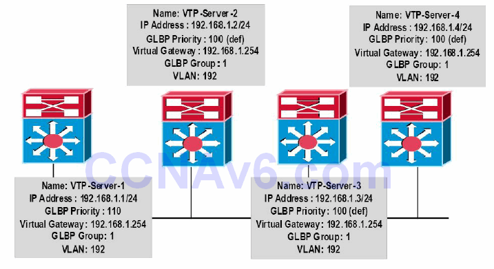
Figure 34.26 – GLBP Configuration Examples Topology
NOTE: It is assumed that VLAN and trunking configuration between the switches is already in place and the switches are successfully able to ping each other across VLAN192. For the sake of brevity, this configuration output will be omitted from the configuration examples.
VTP-Server-1(config)#interface vlan192
VTP-Server-1(config-if)#glbp 1 ip 192.168.1.254
VTP-Server-1(config-if)#glbp 1 priority 110
VTP-Server-1(config-if)#exit
VTP-Server-2(config)#interface vlan192
VTP-Server-2(config-if)#glbp 1 ip 192.168.1.254
VTP-Server-2(config-if)#exit
VTP-Server-3(config)#interface vlan192
VTP-Server-3(config-if)#glbp 1 ip 192.168.1.254
VTP-Server-3(config-if)#exit
VTP-Server-4(config)#interface vlan192
VTP-Server-4(config-if)#glbp 1 ip 192.168.1.254
VTP-Server-4(config-if)#exit
Once the GLBP group has been configured, the show glbp brief command can be used to view a summary of the GLBP configuration, as shown in the following outputs:
VTP-Server-1#show glbp brief
Interface   Grp  Fwd Pri State    Address         Active router  Standby router
Vl192       1    -   110 Active   192.168.1.254   local          192.168.1.4
Vl192       1    1   -   Active   0007.b400.0101  local          -
Vl192       1    2   -   Listen   0007.b400.0102  192.168.1.2    -
Vl192       1    3   -   Listen   0007.b400.0103  192.168.1.3    -
Vl192       1    4   -   Listen   0007.b400.0104  192.168.1.4    -

VTP-Server-2#show glbp brief
Interface   Grp  Fwd Pri State    Address         Active router  Standby router
Vl192       1    -   100 Listen   192.168.1.254   192.168.1.1    192.168.1.4
Vl192       1    1   -   Listen   0007.b400.0101  192.168.1.1    -
Vl192       1    2   -   Active   0007.b400.0102  local          -
Vl192       1    3   -   Listen   0007.b400.0103  192.168.1.3    -
Vl192       1    4   -   Listen   0007.b400.0104  192.168.1.4    -

VTP-Server-3#show glbp brief
Interface   Grp  Fwd Pri State    Address         Active router  Standby router
Vl192       1    -   100 Listen   192.168.1.254   192.168.1.1    192.168.1.4
Vl192       1    1   -   Listen   0007.b400.0101  192.168.1.1    -
Vl192       1    2   -   Listen   0007.b400.0102  192.168.1.2    -
Vl192       1    3   -   Active   0007.b400.0103  local          -
Vl192       1    4   -   Listen   0007.b400.0104  192.168.1.4    -

VTP-Server-4#show glbp brief
Interface   Grp  Fwd Pri State    Address         Active router  Standby router
Vl192       1    -   100 Standby  192.168.1.254   192.168.1.1    local
Vl192       1    1   -   Listen   0007.b400.0101  192.168.1.1    -
Vl192       1    2   -   Listen   0007.b400.0102  192.168.1.2    -
Vl192       1    3   -   Listen   0007.b400.0103  192.168.1.3    -
Vl192       1    4   -   Active   0007.b400.0104  local          -
From the output above, you can see that VTP-Server-1 (192.168.1.1) has been elected as the AVG based on its priority value of 110, which is higher than that of all the other gateways. Gateway VTP-Server-4 (192.168.1.4) has been elected as the standby virtual gateway because it has the highest IP address of the remaining three gateways, even though they all share the same priority value. Gateways VTP-Server-2 and VTP-Server-3 are therefore placed in the Listen state.
The show glbp command prints detailed information on the status of the GLBP group. The output of this command is illustrated as follows:
VTP-Server-1#show glbp
Vlan192 - Group 1
  State is Active
    2 state changes, last state change 02:52:22
  Virtual IP address is 192.168.1.254
  Hello time 3 sec, hold time 10 sec
    Next hello sent in 1.465 secs
  Redirect time 600 sec, forwarder time-out 14400 sec
  Preemption disabled
  Active is local
  Standby is 192.168.1.4, priority 100 (expires in 9.619 sec)
  Priority 110 (configured)
  Weighting 100 (default 100), thresholds: lower 1, upper 100
  Load balancing: round-robin
  Group members:
    0004.c16f.8741 (192.168.1.3)
    000c.cea7.f3a0 (192.168.1.2)
    0013.1986.0a20 (192.168.1.1) local
    0030.803f.ea81 (192.168.1.4)
  There are 4 forwarders (1 active)
  Forwarder 1
    State is Active
      1 state change, last state change 02:52:12
    MAC address is 0007.b400.0101 (default)
    Owner ID is 0013.1986.0a20
    Redirection enabled
    Preemption enabled, min delay 30 sec
    Active is local, weighting 100
  Forwarder 2
    State is Listen
    MAC address is 0007.b400.0102 (learnt)
    Owner ID is 000c.cea7.f3a0
    Redirection enabled, 599.299 sec remaining (maximum 600 sec)
    Time to live: 14399.299 sec (maximum 14400 sec)
    Preemption enabled, min delay 30 sec
    Active is 192.168.1.2 (primary), weighting 100 (expires in 9.295 sec)
  Forwarder 3
    State is Listen
    MAC address is 0007.b400.0103 (learnt)
    Owner ID is 0004.c16f.8741
    Redirection enabled, 599.519 sec remaining (maximum 600 sec)
    Time to live: 14399.519 sec (maximum 14400 sec)
    Preemption enabled, min delay 30 sec
    Active is 192.168.1.3 (primary), weighting 100 (expires in 9.515 sec)
  Forwarder 4
    State is Listen
    MAC address is 0007.b400.0104 (learnt)
    Owner ID is 0030.803f.ea81
    Redirection enabled, 598.514 sec remaining (maximum 600 sec)
    Time to live: 14398.514 sec (maximum 14400 sec)
    Preemption enabled, min delay 30 sec
    Active is 192.168.1.4 (primary), weighting 100 (expires in 8.510 sec)
When executed on the AVG, the show glbp command shows, among other things, the address of the standby virtual gateway and the number of AVFs in the group, as well as the states that it has assigned to them. The virtual MAC addresses for each AVF are also displayed.
Section 34 Questions
- Name two FHRP protocols that are Cisco proprietary.
- Name the open standard FHRP protocol.
- By default, when HSRP is enabled in Cisco IOS software, version 1 is enabled. True or false?
- Which Multicast address does HSRP version 2 use to send Hello packets?
- HSRP version 1 group numbers are restricted to the range of 0 to 255, whereas the version 2 group numbers have been extended from 0 to 4095. True or false?
- Which parameter can be adjusted in order to influence the HSRP primary gatewayelection?
- How does HSRP interface tracking influence the primary gateway election process?
- Which command can you use to configure an HSRP address on an interface?
- Just like HSRP, VRRP has the option of allowing the gateway to use the BIA or a statically configured address as the MAC address for VRRP groups. True or false?
- Which command can you use to configure a GLBP group IP address on a router interface?
Section 34 Answers
- HSRP and GLBP.
- VRRP.
- True.
- 224.0.0.102.
- True.
- HSRP priority.
- It modifies HSRP priority based on interface status.
- The standby [number] ip [virtual address]command.
- False.
- The glbp [number] ip [virtual address] command
Section 34 Labs
HSRP Lab
Test the commands explained in this module, working on a scenario that includes two routers directly connected (i.e., Fa0/0 is connected to Fa0/0). Those routers should connect to a switch using, for example, ports Fa0/1. Connect a workstation on the switch.
- Configure a consistent IP addressing scheme on the two routers, for example, 192.168.0.1/24 and 192.168.0.2/24
- Configure HSRP 10 on the LAN-facing interfaces, using the 192.168.0.10 address
- Name the HSRP group as CCNA
- Control the election of the primary HSRP gateway using the standby 10 priority 110 command
- Verify HSRP configuration using the show standby [brief] command
- Configure HSRP preemption on both routers
- Shut down Router 1 and see how Router 2 becomes primary
- Restart Router 1 and see how it becomes primary again due to preemption being enabled
- Configure the workstation with the IP address 192.168.0.100/24 and the gateway address 192.168.0.10; ping the gateway from the workstation
- Configure interface tracking: track an unused interface on the router using the standby 10 track [int number] command; cycle that interface through different states and see how the corresponding router priority changes based on the interface state
- Configure HSRP version 2 with the standby version 2 command
- Adjust HSRP timers on both routers with the standby 10 timers x y command
- Configure MD5 HSRP authentication between the routers
- Debug HSRP using the debug standby command during a priority change on one of the routers and see how the second one is elected as the primary gateway
VRRP Lab
Repeat the previous lab but this time using VRRP instead of HSRP, with the applicable command changes.
GLBP Lab
Repeat the first lab but this time using GLBP instead of HSRP, with the applicable command changes. Configure GLBP load sharing on the routers using the glbp 10 load-balancing roundrobin command and see how traffic from the LAN hits both routers.

Excelente aporte. Gracias por la información